
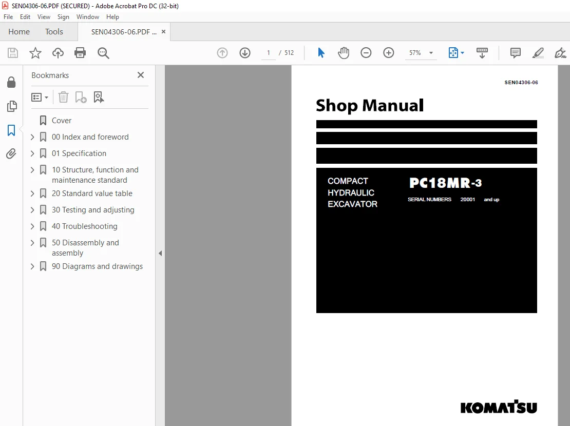
Komatsu COMPACT HYDRAULIC EXCAVATOR PC18MR-3 Shop Manual SEN04306-06 PDF
$30.95
Komatsu COMPACT HYDRAULIC EXCAVATOR PC18MR-3 Shop Manual SEN04306-06 – PDF DOWNLOAD
SERIAL NUMBERS 20001 and up
Description
Komatsu COMPACT HYDRAULIC EXCAVATOR PC18MR-3 Shop Manual SEN04306-06 – PDF DOWNLOAD
FILE DETAILS:
Komatsu COMPACT HYDRAULIC EXCAVATOR PC18MR-3 Shop Manual SEN04306-06 – PDF DOWNLOAD
Language : English
Pages :512
Downloadable : Yes
File Type : PDF
DESCRIPTION:
Komatsu COMPACT HYDRAULIC EXCAVATOR PC18MR-3 Shop Manual SEN04306-06 – PDF DOWNLOAD
SERIAL NUMBERS 20001 and up
1. General precautions k Mistakes in operation are extremely dangerous. Read the Operation and Maintenance Manual carefully before operating the machine. In addition, read this manual and understand its contents before starting the work.
TABLE OF CONTENTS:
Komatsu COMPACT HYDRAULIC EXCAVATOR PC18MR-3 Shop Manual SEN04306-06 – PDF DOWNLOAD
SERIAL NUMBERS 20001 and up
Cover 1
00 Index and foreword 0
100 Index 3
Composition of shop manual 4
Table of contents 6
200 Foreword and general information 11
Safety notice 12
How to read the shop manual 17
Explanation of terms for maintenance standard 19
Handling of electric equipment and hydraulic component 21
Handling of connectors newly used for engines 30
How to read electric wire code 33
Precautions when carrying out operation 36
Method of disassembling and connecting push-pull type coupler 39
Standard tightening torque table 42
Conversion table 46
01 Specification 0
100 Specification and technical data 53
Specification dimension drawing 54
Working range drawing 55
Specifications 56
Weight table 59
Table of fuel, coolant and lubricants 61
10 Structure, function and maintenance standard 0
100 Engine and cooling system 63
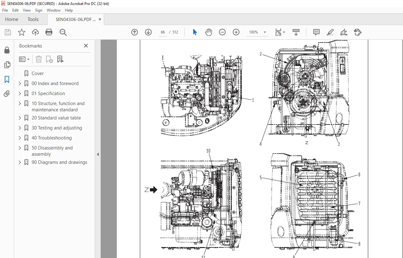
PTO 64
Cooling system 66
200 Power train 69
Power train 70
Swing circle 71
300 Undercarriage and frame 73
Track frame 74
Idler cushion 75
Idler 77
Track roller 78
Sprocket 79
Track shoe 80
410 Hydraulic system, Part 1 83
Hydraulic components layout drawing 84
Hydraulic tank 85
Center swivel joint 86
Travel motor 87
Hydraulic cylinder 96
Solenoid valve100
Variable gauge valve103
Multi-control valve (If equipped)104
420 Hydraulic system, Part 2107
Hydraulic pump108
Control valve114
430 Hydraulic system, Part 3125
CLSS126
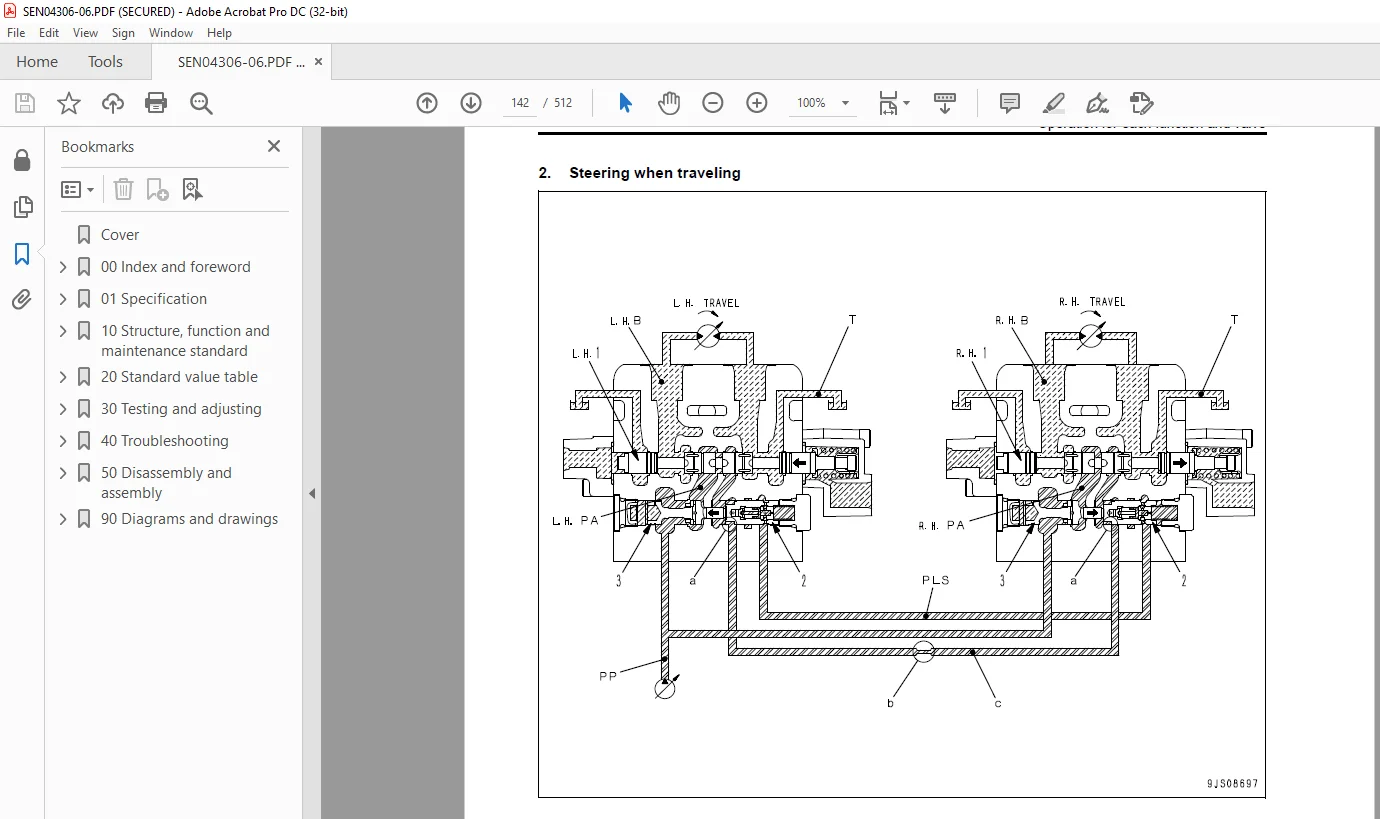
Operation for each function and valve130
Swing motor144
PPC valve147
500 Work equipment157
Work equipment159
Dimensions of each part of work equipment162
600 Cab and its attachments167
Floor168
700 Electrical system171
Engine control system172
Electric control system176
Component parts of system181
KOMTRAX system182
Monitor system185
Sensors188
20 Standard value table 0
100 Standard service value table191
Standard value table for engine related parts192
Standard value table for chassis related parts193
30 Testing and adjusting 0
100 Testing and adjusting203
List of testing, adjusting, and troubleshooting tools205
Measuring engine speed207
Measurement of exhaust gas color208
Adjusting valve clearance209
Testing compression pressure211
Testing engine oil pressure212
Testing and adjusting fuel injection timing213
Adjusting engine stop solenoid215
Bleeding air from fuel circuit216
Testing and adjusting fan belt tension217
Adjusting fuel control lever linkage218
Measurement of clearance in swing circle bearings219
Testing and adjusting track shoe tension220
Testing and adjusting oil pressures in work equipment, travel, swing, and blade circuits222
Testing and adjusting control circuit basic pressure225
Testing and adjusting pump LS differential pressure227
Measuring solenoid valve output pressure229
Measuring PPC valve output pressure231
Adjusting play of work equipment and swing PPC valves233
Measuring swing holding brake release pressure233
Testing oil leakage from cylinder235
Releasing residual pressure from hydraulic circuit237
Bleeding air from cylinder237
Pressurizing hydraulic tank238
How to open and close (tilt) floor239
Inspection procedures for diode241
How to start operation of KOMTRAX terminal242
Lamp display of KOMTRAX terminal246
Removal and installation of KOMTRAX terminal249
Preparation work for troubleshooting of electrical system250
40 Troubleshooting 0
100 General information on troubleshooting253
Points to remember when troubleshooting254
Sequence of events in troubleshooting255
Checks before troubleshooting256
Classification and procedures of troubleshooting257
Connection table for connector pin numbers260
T- branch box and T- branch adapter table296
200 Troubleshooting of electrical system (E-mode)301
Before carrying out troubleshooting for electrical system (E-mode)302
Information contained in troubleshooting table304
E-1 Engine does not start305
E-2 Engine does not stop312
E-3 When starting switch is turned ON, any item does not operate316
E-4 When starting switch is turned ON, some items do not operate318
E-5 Alarm buzzer is abnormal319
E-6 Engine oil pressure caution is turned ON321
E-7 Charge level caution is turned ON322
E-8 Preheating system does not operate or preheater does not become hot325
E-9 Coolant temperature gauge is abnormal326
E-10 Fuel level gauge is abnormal330
E-11 Service meter does not operate while engine is running334
E-12 2nd travel speed is not selected337
E-13 Working lamp does not light up340
E-14 When work equipment lock (PPC basic pressure lock) lever is set in LOCK, work equipment still moves342
E-15 Blade/Variable gauge selector system does not operate normally345
300 Troubleshooting of hydraulic and mechanical system (H-mode)349
Information contained in troubleshooting table351
H-1 Speed or power of whole work equipment, travel, swing, and blade is low352
H-2 Engine speed lowers extremely or engine stalls353
H-3 Whole work equipment, travel system, swing system, and blade do not move354
H-4 Abnormal sound comes out from around hydraulic pump355
H-5 Fine control performance or response is low355
H-6 Speed or power of boom is low356
H-7 Speed or power of arm is low357
H-8 Speed or power of bucket is low358
H-9 Speed or power of boom swing is low359
H-10 Work equipment does not move singly359
H-11 Work equipment hydraulic drift is large360
H-12 Time lag of work equipment is large361
H-13 In compound operation of work equipment, speed of part loaded more is low361
H-14 Machine deviates during travel362
H-15 Travel speed or travel power is low364
H-16 Machine is not steered well or steering power is low364
H-17 Travel speed does not change365
H-18 Travel motor does not work (one side only)365
H-19 Speed or power of swing is low366
H-20 Machine does not swing368
H-21 Swing acceleration performance is low370
H-22 Machine overruns when it stops swinging371
H-23 Large shock is made when machine stops swinging372
H-24 When upper structure stops swinging, it makes large sound372
H-25 Hydraulic drift of swing is large373
H-26 Speed or power of blade is low374
H-27 Blade does not move375
H-28 Hydraulic drift of blade is large375
H-29 Variable gauge does not move376
H-30 Troubleshooting for hydraulic breaker377
400 Troubleshooting of engine (S-mode)381
Troubleshooting chart382
50 Disassembly and assembly 0
100 General information on disassembly and assembly387
How to read this manual388
Coating materials list390
Special tool list393
Sketches of special tools395
200 Engine and cooling system399
Removal and installation of fuel injection pump assembly400
Removal and installation of radiator assembly401
Removal and installation of hydraulic oil cooler assembly403
Removal and installation of engine and hydraulic pump assembly404
300 Power train411
Removal and installation of swing circle assembly412
400 Undercarriage and frame415
Removal and installation of track shoe assembly416
Disassembly and assembly of idler assembly417
Disassembly and assembly of recoil spring419
Disassembly and assembly of track roller assembly421
Assembly of travel motor assembly423
Removal and installation of floor frame assembly432
Removal and installation of revolving frame436
500 Hydraulic system441
Disassembly and assembly of hydraulic pump assembly442
Disassembly and assembly of control valve assembly452
Removal and installation of hydraulic system and center swivel joint assembly458
Disassembly and assembly of center swivel joint assembly460
Removal and installation of swing motor assembly462
Disassembly and assembly of swing motor assembly463
Disassembly and assembly of hydraulic cylinder assembly470
Disassembly and assembly of hydraulic breaker assembly474
600 Work equipment483
Removal and installation of work equipment assembly484
700 Cab and its attachments487
Removal and installation of canopy488
800 Electrical system491
Removal and installation of KOMTRAX terminal492
90 Diagrams and drawings 0
100 Hydraulic diagrams and drawings495
Hydraulic circuit diagram497
200 Electrical diagrams and drawings501
Electrical circuit diagram503
Connector list and stereogram509
IMAGES PREVIEW OF THE MANUAL:
S.M 25/12/24



