
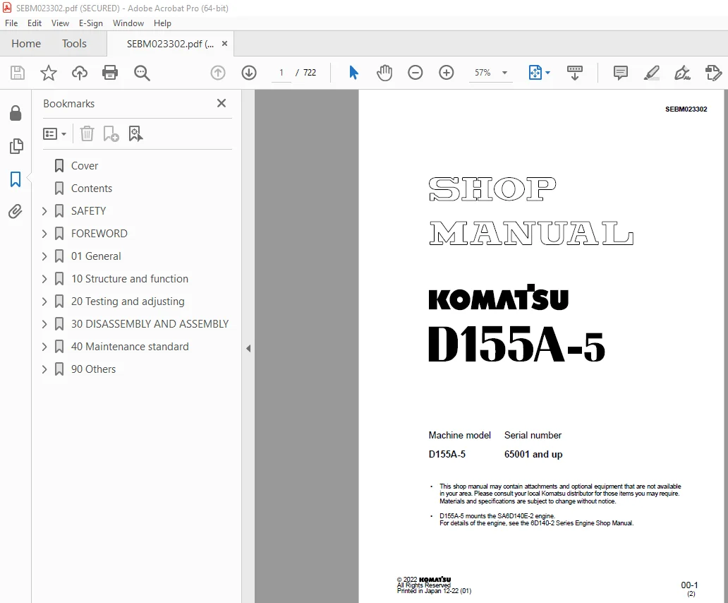

Komatsu D155A-5 Bulldozer Shop Manual SEBM023302 – PDF DOWNLOAD
$32.95
Komatsu D155A-5 Bulldozer Shop Manual SEBM023302 – PDF DOWNLOAD
Description
Komatsu D155A-5 Bulldozer Shop Manual SEBM023302 – PDF DOWNLOAD
FILE DETAILS:
Komatsu D155A-5 Bulldozer Shop Manual SEBM023302 – PDF DOWNLOAD
Language : English
Pages : 722
Downloadable : Yes
File Type : PDF
IMAGES PREVIEW OF THE MANUAL:
TABLE OF CONTENTS:
Komatsu D155A-5 Bulldozer Shop Manual SEBM023302 – PDF DOWNLOAD
Cover 1
Contents 2
SAFETY 3
SAFETY NOTICE 3
FOREWORD 5
GENERAL 5
HOW TO READ THE SHOP MANUAL 6
HOISTING INSTRUCTIONS 7
METHOD OF DISASSEMBLING, CONNECTING PUSH-PULL TYPE COUPLER 8
COATING MATERIALS 10
STANDARD TIGHTENING TORQUE 12
ELECTRIC WIRE CODE 15
CONVERSION TABLE 16
UNITS 22
01 General 23
Specification drawing 24
Specifications 26
Weight table 32
Table of fuel, coolant and lubricants 34
10 Structure and function 35
Radiator 36
Oil cooler 38
Engine control 40
Power train 42
Power train system 43
Power train unit mount 44
Overall drawing of power train unit 45
Power train hydraulic piping diagram 46
Power train hydraulic system drawing 48
Damper, universal joint 50
Torque converter, PTO 52
Transmission control 54
Transmission 56
Transmission control valve 62
Main relief valve 67
Lubrication relief valve 69
Steering, brake control 70
Bevel gear shaft, steering clutch, steering brake 72
Steering control valve 78
Reducing valve 85
Scavenging pump strainer 86
Power train pump strainer 87
Power train oil filter 88
Final drive 90
Radiator guard 93
Main frame, underguard 95
Track frame 96
Recoil spring 98
Track roller bogie 99
Suspension 100
Work equipment hydraulic piping diagram 102
PPC control piping diagram 105
Work equipment control 106
Work equipment hydraulic system diagram 108
Hydraulic tank and filter 112
PPC charge valve 114
Accumulator 116
PPC lock valve 117
PPC valve 118
Main control valve 130
Operation of main control valve 133
Operation of work equipment control circuit 148
Piston valve 152
Quick drop valve 153
Cylinder stay 154
Work equipment 155
Pin puller switch 159
Pin puller solenoid valve 160
Tilt/pitch selector switch 162
Pitch solenoid valve 163
Cab mount 165
Cab 166
Air conditioner 168
Electrical wiring diagram 169
Machine monitor system 170
Sensors 176
Engine starting system 179
20 Testing and adjusting 181
Standard value tables 182
Standard value table for engine related parts 182
Standard value table for chassis related parts 183
Standard value table for machine monitor 188
Testing and adjusting 191
Tools for testing, adjusting, and troubleshooting 192
Measuring engine speed 193
Measuring exhaust color 194
Adjusting valve clearance 195
Measuring compression pressure 196
Measuring blow-by 197
Measuring engine oil pressure 198
Testing and adjusting fuel injection timing 199
Testing and adjusting alternator belt tension 200
Measuring exhaust temperature 201
Measuring air supply pressure (boost pressure) 202
Measuring torque converter stall speed 203
Measuring torque converter stall + hydraulic pump relief (full stall) speed 204
Adjusting fuel control linkage 206
Adjusting decelerator pedal 208
Adjusting joystick (steering, directional, gear shift lever), parking lever linkage 210
Adjusting brake pedal linkage 214
Adjusting work equipment control linkage 215
Testing and adjusting work equipment control circuit pressure 216
Measuring PPC valve output pressure 217
Adjusting PPC valve 218
Measuring on-off solenoid valve output pressure 219
Measuring power train oil pressure 220
Testing and adjusting work equipment main relief pressure 223
Bleeding air from hydraulic cylinders 224
Releasing remaining pressure in hydraulic circuit 224
Checking location of cause of hydraulic drift of blade and ripper 225
Measuring leakage inside cylinder 226
Adjusting semi-U-tiltdozer 227
Adjusting clearance of idler 229
Simple procedure for testing brake performance 230
Troubleshooting 231
Points to remember when troubleshooting 232
Sequence of events in troubleshooting 233
Points to remember when carrying out maintenance 234
Checks before troubleshooting 242
Type of connector and position of installation 244
Connector arrangement diagram 245
Connection table for connector pin numbers 247
Method of using troubleshooting charts 257
Troubleshooting of electrical system (E mode) 259
E-1 Engine does not start 260
E-2 Pin-puller cylinder does not work (machines with giant ripper only) 263
E-3 Blade pitch does not work 264
Troubleshooting of hydraulic and mechanical systems (H mode) 265
Table of failure modes and causes (Hydraulic and mechanical systems) 266
H-1 Machine travels only in one direction (forward or in reverse) 268
H-2 Machine does not move (F2, F3, engine running) 270
H-3 Machine does not move in any speed range 272
H-4 Time lag is excessive when shifting gear or changing direction (forward/reverse) 274
H-5 Machine lacks power (lacks drawbar pull) 276
H-6 Machine does not turn (can travel in straight line) 278
H-7 Machine turns too far 279
H-8 Machine turns only in one direction (left or right) (joystick (steering, directional, gear shift lever) operated) 280
H-9 Brakes do not work 281
H-10 Power train oil overheats 282
H-101 All work equipment speeds are slow 284
H-102 Work equipment does not move 285
H-103 Blade RAISE speed is slow or lacks power 286
H-104 Blade tilt speed is slow or lacks power 286
H-105 Ripper RAISE speed is slow or lacks power 287
H-106 Ripper tilt speed is slow or lacks power 287
H-107 Excessive hydraulic drift of blade lift 288
H-108 Excessive hydraulic drift of blade tilt 288
H-109 Excessive hydraulic drift of ripper 289
H-110 Pin-puller cylinder does not work (machines with giant ripper only) 289
H-111 Blade pitch does not work 290
H-112 Abnormal noise from around hydraulic pump 290
Troubleshooting of machine monitor system (M mode) 291
Electrical circuit diagram for machine monitor related parts 292
M-1 Monitor panel display does not appear when starting switch is turned ON 293
M-2 When starting switch is turned ON, monitor panel lamps all light up but do not go out 293
M-3 Abnormality in preheating 294
a) Preheating monitor lamp does not light up 294
b) Preheating monitor lamp is lighted up continuously 294
M-4 Caution item lights up or flashes 296
a) (Battery charge) lights up or flashes 296
b) When starting switch is turned ON and engine is started, (Engine oil pressure) lights up or flashes 297
c) (Coolant temperature) flashes 298
d) (Power train oil temperature) flashes 299
M-5 Abnormality in buzzer 300
a) Caution item flashes but buzzer does not sound 300
b) Monitor display is normal but buzzer sounds 300
M-6 Abnormality in warning lamp 301
a) Caution item flashes but lamp does not flash 301
b) Monitor display is normal but lamp lights up 301
M-7 Abnormality in gauge 302
a) Abnormality in engine coolant temperature gauge 302
b) Abnormality in power train oil temperature gauge 303
c) Abnormality in fuel level gauge 304
M-8 Service meter does not move after engine is started 305
M-9 Monitor panel lighting does not light up (front lamp is normal) 306
M-10 Lamp does not light up 307
a) Front lamp 307
b) Rear lamp (ripper lamp) 308
M-11 Automatic preheating is not carried out when glow switch is set to AUTO 310
M-12 Wiper does not work 312
M-13 Washer fluid is not sprayed out 316
M-14 Air conditioner has no effect 318
a) Air does not blow out 318
b) There is no cooling effect 322
M-15 Defective operation of backup alarm 326
a) Backup alarm does not sound 326
b) Backup alarm continues to sound 326
30 DISASSEMBLY AND ASSEMBLY 327
METHOD OF USING MANUAL 331
PRECAUTIONS WHEN CARRYING OUT OPERATION 333
SPECIAL TOOL LIST 335
SPECIAL TOOL SKETCH 344
STARTING MOTOR 352
REMOVAL 352
INSTALLATION 352
ALTERNATOR 353
REMOVAL 353
INSTALLATION 353
ENGINE OIL COOLER CORE 354
REMOVAL 354
INSTALLATION 354
FUEL INJECTION PUMP 355
REMOVAL 355
INSTALLATION 356
WATER PUMP 357
REMOVAL 357
INSTALLATION 357
TURBOCHARGER 358
REMOVAL 358
INSTALLATION 358
NOZZLE HOLDER 359
REMOVAL 359
INSTALLATION 359
ENGINE FRONT SEAL 360
REMOVAL 360
INSTALLATION 360
ENGINE REAR SEAL 361
REMOVAL 361
INSTALLATION 362
CYLINDER HEAD 365
REMOVAL 365
INSTALLATION 370
THERMOSTAT 372
REMOVAL 372
INSTALLATION 372
AIR CONDITIONER COMPRESSOR 373
REMOVAL 373
INSTALLATION 374
AIR CONDITIONER CONDENSER 375
REMOVAL 375
INSTALLATION 376
FUEL TANK 377
REMOVAL 377
INSTALLATION 378
RADIATOR 379
REMOVAL 379
INSTALLATION 381
RADIATOR, OIL COOLER, GUARD 382
REMOVAL 382
INSTALLATION 384
FAN DRIVE 385
REMOVAL 385
INSTALLATION 387
HYDRAULIC COOLER 388
REMOVAL 388
INSTALLATION 388
ENGINE 389
REMOVAL 389
INSTALLATION 390
DAMPER 391
REMOVAL 391
INSTALLATION 392
DISASSEMBLY 393
ASSEMBLY 396
POWER TRAIN UNIT 400
REMOVAL 400
INSTALLATION 405
SEPARATION 406
CONNECTION 411
PTO 414
DISASSEMBLY 414
ASSEMBLY 420
TORQUE CONVERTER 426
DISASSEMBLY 426
ASSEMBLY 429
TORQFLOW TRANSMISSION 432
DISASSEMBLY 432
ASSEMBLY 441
STEERING CASE 452
DISASSEMBLY 452
ASSEMBLY 460
POWER TRAIN, LUBRICATION PUMP 471
REMOVAL 471
INSTALLATION 471
SCAVENGING PUMP 472
REMOVAL 472
INSTALLATION 472
POWER TRAIN MAIN RELIEF VALVE 473
REMOVAL 473
INSTALLATION 473
DISASSEMBLY 474
ASSEMBLY 474
TRANSMISSION CONTROL VALVE 475
REMOVAL 475
INSTALLATION 476
DISASSEMBLY 478
ASSEMBLY 478
REDUCING VALVE 481
REMOVAL 481
INSTALLATION 481
DISASSEMBLY 482
ASSEMBLY 482
STEERINGCONTROL VALVE 483
REMOVAL 483
INSTALLATION 483
DISASSEMBLY 484
ASSEMBLY 486
FINAL DRIVE 488
REMOVAL 488
INSTALLATION 491
DISASSEMBLY 492
ASSEMBLY 497
TRACK FRAME 503
REMOVAL 503
INSTALLATION 505
IDLER 506
REMOVAL 506
INSTALLATION 507
DISASSEMBLY 508
ASSEMBLY 510
RECOIL SPRING 513
REMOVAL 513
INSTALLATION 513
DISASSEMBLY 514
ASSEMBLY 519
TRACK ROLLER 524
REMOVAL 524
INSTALLATION 525
DISASSEMBLY 526
ASSEMBLY 529
BOGIE 532
REMOVAL 532
INSTALLATION 534
DISASSEMBLY 535
ASSEMBLY 538
CARRIER ROLLER 542
REMOVAL 542
INSTALLATION 542
DISASSEMBLY 543
ASSEMBLY 545
TRACK SHOE 548
CHECKING BEFORE REMOVAL 548
REMOVAL (NORMAL) 548
REMOVAL (WHEN THERE IS ABNORMALITY INSIDE TRACK FRAME) 549
INSTALLATION 550
OVERALL DISASSEMBLY 551
OVERALL ASSEMBLY 556
PRESS-FITTING JIG DIMENSION TABLE FOR LINK PRESS 570
ONE LINK 571
DISASSEMBLY 571
ASSEMBLY 573
MASTER LINK 575
DISASSEMBLY 575
ASSEMBLY 577
PIVOT SHAFT 580
REMOVAL 580
INSTALLATION 580
EQUALIZER BAR 581
REMOVAL 581
INSTALLATION 582
EQUALIZER BAR SIDE BUSHING 583
REMOVAL 583
INSTALLATION 583
SEGMENT TEETH 584
REMOVAL 584
INSTALLATION 584
HYDRAULIC TANK 585
REMOVAL 585
INSTALLATION 585
HYDRAULIC, PPC PUMP 586
REMOVAL 586
INSTALLATION 586
MAIN CONTROL VALVE 587
REMOVAL 587
INSTALLATION 588
DISASSEMBLY 589
ASSEMBLY 592
PPC CHARGE VALVE 596
REMOVAL 596
INSTALLATION 596
DISASSEMBLY 597
ASSEMBLY 597
BLADE PPC VALVE 598
REMOVAL 598
INSTALLATION 599
RIPPER PPC VALVE 600
REMOVAL 600
INSTALLATION 601
BLADE PPC VALVE 602
DISASSEMBLY 602
ASSEMBLY 603
BLADE LIFT CYLINDER 606
REMOVAL 606
INSTALLATION 606
BLADE TILT CYLINDER 607
REMOVAL 607
INSTALLATION 607
RIPPER LIFT CYLINDER 608
REMOVAL 608
INSTALLATION 608
RIPPER TILT CYLINDER 609
REMOVAL 609
INSTALLATION 609
HYDRAULIC CYLINDER 610
DISASSEMBLY 610
ASSEMBLY 613
BLADE 617
REMOVAL 617
INSTALLATION 618
DISASSEMBLY 619
ASSEMBLY 621
MULTI-SHANK RIPPER 623
DISASSEMBLY 623
ASSEMBLY 625
ROPS GUARD 627
REMOVAL 627
INSTALLATION 627
OPERATOR CAB 628
REMOVAL 628
INSTALLATION 628
HOOD 629
REMOVAL 629
INSTALLATION 629
FLOOR FRAME 630
REMOVAL 630
INSTALLATION 635
DASHBOARD 636
REMOVAL 636
INSTALLATION 637
MONITOR 638
REMOVAL 638
INSTALLATION 638
40 Maintenance standard 639
Engine mount 640
Power train unit mount 641
Damper, universal joint 642
Torque converter, PTO 644
Transmission 646
Transmission control valve 649
Main relief valve 650
Bevel gear shaft, steering clutch, steering brake 652
Steering control valve 656
Scavenging pump 658
Power train pump, lubrication pump 659
Final drive 660
Main frame 662
Track frame 664
Recoil spring 665
Track roller bogie 666
Idler 668
Track roller 670
Carrier roller 672
Recoil spring 673
Track shoe (Dry type track) 674
Track shoe (Sealed and Lubricated Track) 678
Suspension 682
Hydraulic, PPC charge pump 684
PPC charge valve 685
PPC valve 686
Main control valve 691
Work equipment cylinder 696
Quick drop valve 700
Cylinder stay 701
Work equipment 702
90 Others 711
Hydraulic circuit diagram 713
Power train hydraulic circuit diagram 713
Work equipment hydraulic circuit diagram 715
Electrical circuit diagram 719
ELECTRICAL CIRCUIT DIAGRAM 719
Cab electrical circuit diagram 721
DESCRIPTION:
Komatsu D155A-5 Bulldozer Shop Manual SEBM023302 – PDF DOWNLOAD
FOREWORD:
GENERAL:
- This shop manual has been prepared as an aid to improve the quality of repairs by giving the serviceman an
accurate understanding of the product and by showing him the correct way to perform repairs and make judgements.
Make sure you understand the contents of this manual and use it to full effect at every opportunity. - This shop manual mainly contains the necessary technical information for operations performed in a service
workshop. For ease of understanding, the manual is divided into the following chapters; these chapters are further
divided into the each main group of components.
STRUCTURE AND FUNCTION
This section explains the structure and function of each component. It serves not only to give an understanding
of the structure, but also serves as reference material for troubleshooting.
In addition, this section may contain hydraulic circuit diagrams, electric circuit diagrams, and maintenance
standards.
TESTING AND ADJUSTING
This section explains checks to be made before and after performing repairs, as well as adjustments to
be made at completion of the checks and repairs.
Troubleshooting charts correlating “Problems” with “Causes” are also included in this section.
DISASSEMBLY AND ASSEMBLY
This section explains the procedures for removing, installing, disassembling and assembling each component,
as well as precautions for them.
MAINTENANCE STANDARD
This section gives the judgment standards for inspection of disassembled parts.
The contents of this section may be described in STRUCTURE AND FUNCTION.
OTHERS
This section mainly gives hydraulic circuit diagrams and electric circuit diagrams.
In addition, this section may give the specifications of attachments and options together.
S.V 24/12/24



