Komatsu D155A-6 Bulldozer Shop Manual SEN02854-25 PDF
$38.95
Komatsu D155A-6 Bulldozer Shop Manual SEN02854-25 – PDF DOWNLOAD
SERIAL NUMBERS 85001 and up
Description
Komatsu D155A-6 Bulldozer Shop Manual SEN02854-25 – PDF DOWNLOAD
FILE DETAILS:
Komatsu D155A-6 Bulldozer Shop Manual SEN02854-25 – PDF DOWNLOAD
Language : English
Pages : 1566
Downloadable : Yes
File Type : PDF
IMAGES PREVIEW OF THE MANUAL:
TABLE OF CONTENTS:
Komatsu D155A-6 Bulldozer Shop Manual SEN02854-25 – PDF DOWNLOAD
SERIAL NUMBERS 85001 and up
Cover 1
00 Index and foreword 3
Index 3
Composition of shop manual 4
Table of contents 6
Foreword and general information 17
Safety notice 18
How to read the shop manual 23
Explanation of terms for maintenance standard 25
Handling of electric equipment and hydraulic component 27
Handling of connectors newly used for engines 36
How to read electric wire code 39
Precautions when carrying out operation 42
Method of disassembling and connecting push-pull type coupler 45
Standard tightening torque table 48
Conversion table 52
01 Specification 59
Specification and technical data 59
Specification dimension drawings 60
Specifications 61
Weight table 67
Table of fuel, coolant and lubricants 70
10 Structure, function and maintenance standard 73
Engine and cooling system 73
Radiator, oil cooler 74
Engine mount 81
Cooling fan pump 82
Cooling fan motor 90
Power train, Part 1 97
Power train skeleton 98
Overall drawing of power train unit 100
Power train hydraulic piping drawing 102
Damper, universal joint 104
Torque converter, PTO 106
Transmission 114
Transmission ECMV 130
Main relief valve and torque converter relief valve 136
Lubricating oil relief valve 138
Scavenging pump 140
Power train and steering lubrication pump 142
Power train, Part 2 145
Work equipment pump 146
Work equipment cooler bypass valve 159
Steering, brake control 160
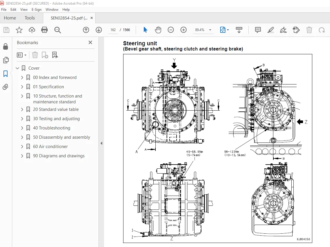
Steering unit 162
Steering control valve 176
Steering clutch ECMV, steering brake ECMV 178
Parking brake solenoid valve 184
Sudden stop prevention valve 186
Final drive 189
Sprocket 194
Undercarriage and frame 197
Track frame 198
Recoil spring 200
Idler 202
Track roller 204
Carrier roller 206
Track shoe 208
Main frame 214
Suspension 216
Hydraulic system 219
Work equipment hydraulic piping diagram 220
Work equipment control piping diagram 224
Work equipment control 226
Hydraulic tank and filter 228
Accumulator 231
PPC valve 232
Work equipment lock valve 244
Control valve 246
Work equipment cylinder 268
Piston valve 270
Quick drop valve 272
Self pressure reducing valve 273
Work equipment 281
Cylinder stay 282
Blade 284
Ripper 288
Cutting edge, end bit 286
Cab and its attachments 295
Cab mount + ROPS pin 296
ROPS cab 297
ROPS floor 298
Air conditioner 299
Electrical system 301
Engine control 302
Engine control system 303
Deceleration potentiometer 304
Monitor system 306
Sensors 325
Palm command control system 328
KOMTRAX system 331
20 Standard value table 335
Standard service value table 335
Standard value table for engine 336
Standard value table for machine 337
30 Testing and adjusting 347
Testing and adjusting, Part 1 347
Tools for testing, adjusting, and troubleshooting 349
Sketches of special tools 354
Measuring engine speed 357
Measuring intake air pressure (boost pressure) 359
Measuring exhaust temperature 361
Measuring exhaust gas color 363
Adjusting valve clearance 364
Measuring compression pressure 365
Measuring blow-by pressure 367
Measuring engine oil pressure 368
Handling fuel system parts 369
Releasing residual pressure from fuel system 369
Measuring fuel pressure 370
Measuring fuel return rate and fuel leakage 371
Bleeding air from fuel circuit 375
Measuring fuel circuit for leakage 377
Testing and adjusting alternator belt tension 378
Testing and adjusting air conditioner compressor belt tension 379
Measuring fan speed 380
Measuring fan circuit oil pressure 382
Bleeding air from fan pump 383
Bleeding air from work equipment pump 384
Adjusting fuel control dial and decelerator pedal 385
Testing and adjusting, Part 2 389
Measuring power train oil pressure 391
Adjusting transmission output shaft speed sensor 399
Simple test procedure for brake performance 400
Adjusting brake pedal 401
Adjusting parking brake lever 403
Emergency escape method when power train has trouble 405
Adjusting idler clearance 408
Testing and adjusting track shoe tension 410
Measuring and adjusting work equipment oil pressure 411
Measuring control circuit basic pressure 414
Measuring work equipment lock solenoid valve output pressure (PPC valve basic pressure) 415
Measuring PPC valve output pressure 416
Adjusting work equipment PPC valve play 418
Measuring ripper pin puller solenoid valve output pressure 420
Testing parts which cause hydraulic drift of blade and ripper 421
Measuring internal leakage of work equipment cylinder 422
Releasing residual pressure from work equipment cylinder 423
Bleeding air from work equipment cylinder 423
Adjusting work equipment lock lever 424
Adjusting blade 425
Testing and adjusting play of blade electric lever 427
Adjusting operator’s cab 435
Testing and adjusting, Part 3 441
Special functions of machine monitor (EMMS) 442
Testing and adjusting, Part 4 503
Handling of power supply circuit of engine controller 504
Preparation work for troubleshooting of electrical system 505
Pm Clinic 507
40 Troubleshooting 519
Failure code table and fuse locations 519
Failure codes table 520
Fuse locations 526
General information on troubleshooting 531
Points to remember when troubleshooting 532
Sequence of events in troubleshooting 533
Check before troubleshooting 534
Classification and procedures for troubleshooting 535
Information in troubleshooting table 538
Connection table for connector pin numbers 540
T- branch box and T- branch adapter table 576
Troubleshooting by failure and error codes, Part 1 581
Failure code [1500L0] 583
Failure code [15SAL1] 584
Failure code [15SALH] 586
Failure code [15SBL1] 588
Failure code [15SBLH] 590
Failure code [15SEL1] 592
Failure code [15SELH] 594
Failure code [15SFL1] 596
Failure code [15SFLH] 598
Failure code [15SGL1] 600
Failure code [15SGLH] 602
Failure code [2201L1] 604
Failure code [2201LH] 606
Failure code [2202L1] 608
Failure code [2202LH] 610
Failure code [2300KM] 612
Failure code [2301L1] 613
Failure code [2301LH] 615
Failure code [2302L1] 617
Failure code [2302LH] 619
Failure code [7RFAKA] 621
Failure code [AA10NX] 623
Failure code [AB00MA] 625
Failure code [B@BAZG] 627
Failure code [B@BCNS] 628
Failure code [B@BCZK] 629
Failure code [B@CENS] 630
Failure code [B@HANS] 631
Failure code [CA111] 632
Failure code [CA115] 634
Failure code [CA122] 636
Failure code [CA123] 639
Failure code [CA131] 640
Failure code [CA132] 642
Failure code [CA135] 643
Failure code [CA141] 646
Failure code [CA144] 647
Failure code [CA145] 649
Failure code [CA153] 650
Failure code [CA154] 652
Failure code [CA187] 652
Failure code [CA221] 653
Failure code [CA222] 656
Failure code [CA227] 657
Troubleshooting by failure and error codes, Part 2 661
Failure code [CA234] 663
Failure code [CA238] 664
Failure code [CA263] 666
Failure code [CA265] 668
Failure code [CA271] 669
Failure code [CA272] 671
Failure code [CA273] 673
Failure code [CA274] 675
Failure code [CA322] 677
Failure code [CA323] 679
Failure code [CA324] 681
Failure code [CA325] 683
Failure code [CA331] 685
Failure code [CA332] 687
Failure code [CA342] 689
Failure code [CA351] 690
Failure code [CA352] 692
Failure code [CA386] 693
Failure code [CA441] 695
Failure code [CA442] 695
Failure code [CA449] 696
Failure code [CA451] 697
Failure code [CA452] 700
Failure code [CA553] 701
Failure code [CA554] 703
Failure code [CA559] 704
Failure code [CA689] 710
Failure code [CA731] 712
Failure code [CA757] 713
Failure code [CA778] 714
Failure code [CA1633] 717
Failure code [CA2185] 719
Failure code [CA2186] 721
Failure code [CA2249] 721
Failure code [CA2555] 722
Failure code [CA2556] 723
Failure code [D110KA] 725
Failure code [D110KB] 727
Failure code [D130KA] 729
Failure code [D130KB] 732
Failure code [D161KA] 734
Failure code [D161KB] 736
Failure code [D190KA] 738
Failure code [D190KB] 740
Troubleshooting by failure and error codes, Part 3 743
Failure code [D5ZKKX] 745
Failure code [DAFRKR] 748
Failure code [DAFRMC] 750
Failure code [DB2RKR] 757
Failure code [DB90KR] 760
Failure code [DBE0KK] 762
Failure code [DBE0KT] 765
Failure code [DBE6KK] 766
Failure code [DBE7KK] 768
Failure code [DBE9KQ] 771
Failure code [DD12KA] 773
Failure code [DD12KB] 775
Failure code [DD13KA] 777
Failure code [DD13KB] 779
Failure code [DD14KA] 781
Failure code [DD14KB] 783
Failure code [DDDDKA] 785
Failure code [DDDDKB] 787
Failure code [DDDDKX] 789
Failure code [DGT1KA] 790
Failure code [DGT1KX] 792
Failure code [DH21KA] 794
Failure code [DH21KB] 796
Failure code [DK10KX] 798
Failure code [DK30KA] 801
Failure code [DK30KB] 803
Failure code [DK30KX] 805
Failure code [DK30KZ] 805
Failure code [DK30L8] 806
Failure code [DK31KA] 807
Failure code [DK31KB] 809
Failure code [DK40KA] 811
Failure code [DK40KB] 813
Failure code [DK55KX] 815
Failure code [DK55KZ] 815
Failure code [DK55L8] 816
Failure code [DK56KA] 817
Failure code [DK56KB] 819
Troubleshooting by failure and error codes, Part 4 823
Failure code [DK57KA] 826
Failure code [DK57KB] 828
Failure code [DKH1KA] 830
Failure code [DKH1KB] 832
Failure code [DLT3KA] 834
Failure code [DLT3KB] 836
Failure code [DW7BKA] 838
Failure code [DW7BKB] 840
Failure code [DWN3KA] 842
Failure code [DWN3KB] 844
Failure code [DWN3KY] 846
Failure code [DWN5KA] 848
Failure code [DWN5KB] 850
Failure code [DXH4KA] 852
Failure code [DXH4KB] 854
Failure code [DXH4KY] 856
Failure code [DXH5KA] 858
Failure code [DXH5KB] 860
Failure code [DXH5KY] 862
Failure code [DXH6KA] 864
Failure code [DXH6KB] 866
Failure code [DXH6KY] 868
Failure code [DXH7KA] 870
Failure code [DXH7KB] 872
Failure code [DXH7KY] 874
Failure code [DXH8KA] 876
Failure code [DXH8KB] 878
Failure code [DXH8KY] 880
Failure code [DXH9KA] 882
Failure code [DXH9KB] 884
Failure code [DXH9KY] 886
Failure code [DXHAKA] 888
Failure code [DXHAKB] 890
Failure code [DXHAKY] 892
Failure code [DXHBKA] 894
Failure code [DXHBKB] 896
Failure code [DXHBKY] 898
Failure code [DXHCKA] 900
Failure code [DXHCKB] 902
Failure code [DXHCKY] 904
Failure code [DXJ4KA] 906
Failure code [DXJ4KB] 908
Troubleshooting of electrical system (E-mode) 911
Before carrying out troubleshooting for electrical system 913
Information in troubleshooting table 917
E-1 When starting switch turned ON, machine monitor displays nothing 918
E-2 When starting switch turned ON (before starting engine), basic check item lights up 1 920
E-3 Engine does not start (Engine does not turn) 922
E-4 Preheater does not operate 925
E-5 Precaution item lights up while engine is running 928
E-6 Emergency stop item lights up while engine is running 930
E-7 Engine coolant temperature gauge does not indicate normally 932
E-8 Fuel level gauge does not indicate normally 933
E-9 Power train oil temperature gauge (multi-gauge) does not indicate normally 935
E-10 Hydraulic temperature gauge (multi-gauge) does not indicate normally 936
E-11 Contents of display by machine monitor are different from applicable machine 938
E-12 Machine monitor does not display some items 938
E-13 Function switch does not work 938
E-14 Operation mode does not change 939
E-15 Gearshift mode does not change 939
E-16 Customize function does not operate normally 940
E-17 Customize memory function does not normally 940
E-18 Alarm buzzer cannot be stopped 941
E-19 Air conditioner does not operate normally (including air conditioner fault history) 942
E-20 When starting switch is turned OFF, service meter is not displayed 956
E-21 Machine monitor cannot be set in service mode 956
E-22 Ripper pin puller cylinder does not operate 958
E-23 Backup alarm does not sound or does not stop 960
E-24 Headlamp, rear lamp, and ripper point lamp do not light up 962
E-25 Windshield wiper and window washer do not operate 967
E-26 KOMTRAX terminal does not operate normally 983
E-27 Fan does not reverse 984
E-28 Gear cannot be shifted 986
E-29 Electric priming pump does not operate or does not stop automatically 988
Troubleshooting of hydraulic and mechanical system (H-mode) 991
Information in troubleshooting table 993
H-1 Power is low (Drawbar pull is low) 994
H-2 Machine does not travel (at 2nd or 3rd gear speed) 995
H-3 Machine does not start at any gear speed 996
H-4 Machine can travel only forward or in reverse 997
H-5 When gear speed or travel direction is changed, time lag is large 998
H-6 Steering is not possible 999
H-7 Steering is possible only on one side 1000
H-8 Steering overrun occurs 1001
H-9 Brake does not work 1002
H-10 Power train oil is overheated 1003
H-11 Speed of all work equipment is low 1004
H-12 No work equipment moves 1005
H-13 Blade lift speed or power is low 1006
H-14 Blade tilt speed or power is low 1007
H-15 Ripper lift speed or power is low 1008
H-16 Ripper tilt speed or power is low 1009
H-17 Hydraulic drift of blade lift is large 1009
H-18 Hydraulic drift of blade tilt is large 1010
H-19 Hydraulic drift of ripper lift is large 1010
H-20 Ripper pin puller cylinder does not operate 1011
H-21 Abnormal sound comes out from around work equipment pump 1012
H-22 Fan speed is abnormal (Sound and/or vibration are abnormally large or engine over heats) 1013
Troubleshooting of engine (S-mode) 1015
Method of using troubleshooting chart 1017
S-1 Starting performance of engine is poor 1020
S-2 Engine does not start 1021
S-3 Engine does not pick up smoothly 1024
S-4 Engine stops during operation 1025
S-5 Engine does not rotate smoothly 1026
S-6 Engine lack output (or lacks power) 1027
S-7 Exhaust gas is black (incomplete combustion) 1028
S-8 Oil consumption is excessive (or exhaust gas is blue) 1029
S-9 Oil becomes dirty quickly 1030
S-10 Fuel consumption is excessive 1031
S-11 Oil is in coolant (or coolant spurts back or coolant level goes down) 1032
S-12 Oil pressure drops 1033
S-13 Oil level rises (Entry of coolant or fuel) 1034
S-14 Coolant temperature becomes too high (Overheating) 1035
S-15 Abnormal noise is made 1036
S-16 Vibration is excessive 1037
S-17 Air cannot be bled from fuel circuit 1038
50 Disassembly and assembly 1041
General information on disassembly and assembly 1041
How to read this manual 1042
Coating materials list 1044
Special tool list 1047
Sketches of special tools 1055
Engine and cooling system 1067
Removal and installation of fuel supply pump assembly 1068
Removal and installation of fuel injector assembly 1073
Removal and installation of cylinder head assembly 1079
Removal and installation of radiator assembly 1090
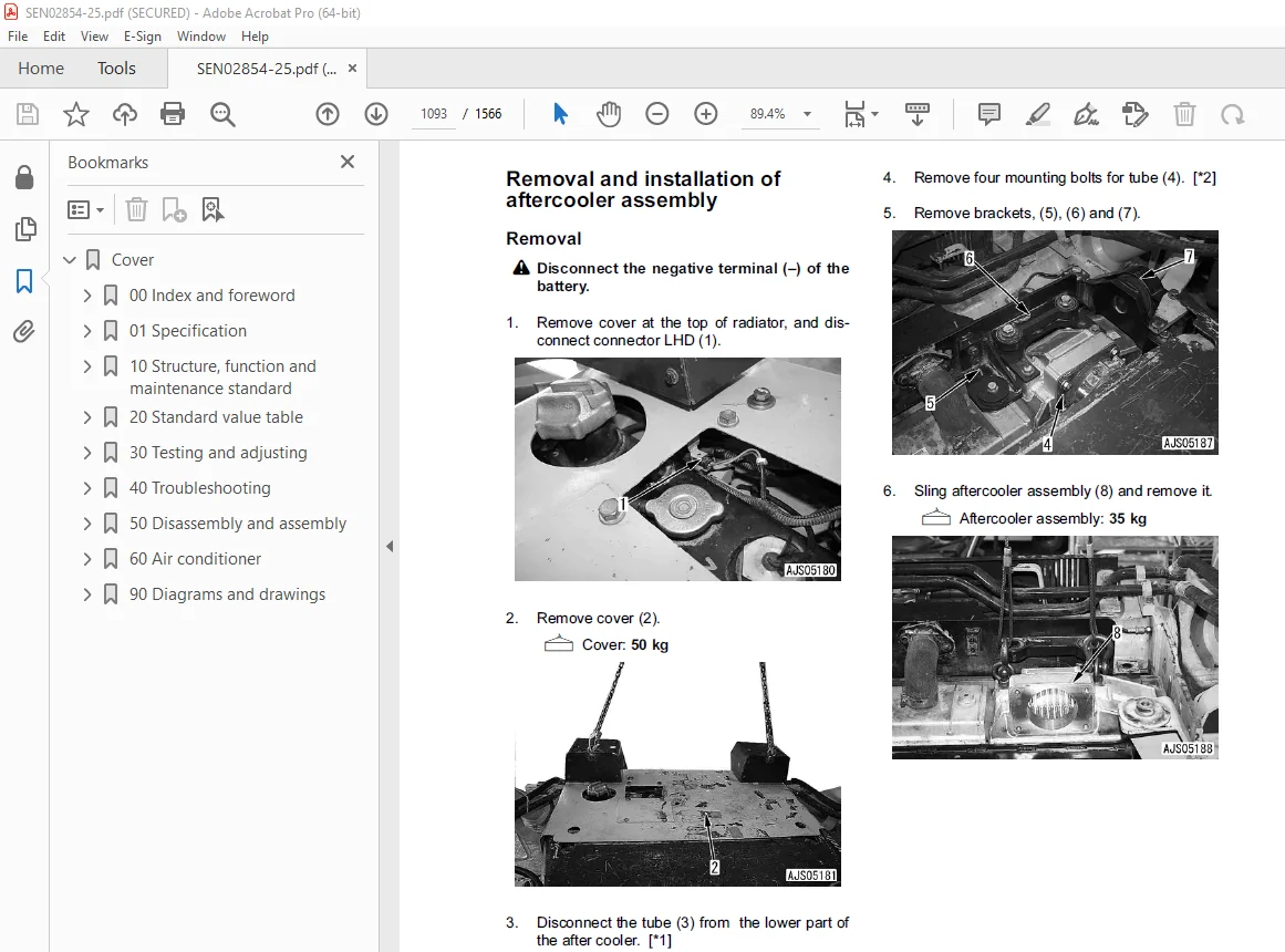
Removal and installation of aftercooler assembly 1093
Removal and installation of engine assembly 1096
Removal and installation of engine hood assembly 1101
Removal and installation of engine front seal 1103
Removal and installation of engine rear seal 1107
Removal and installation of fuel tank assembly 1112
Removal and installation of fan drive assembly 1114
Removal and installation of fan motor assembly 1115
Power train, Part 1 1117
Removal and installation of damper assembly 1118
Disassembly and assembly of damper assembly 1121
Removal and installation of power train unit assembly 1127
Disconnection and connection of power train unit assembly 1132
Power train, Part 2 1139
Disassembly and assembly of PTO assembly 1140
Disassembly and assembly of torque converter assembly 1147
Disassembly and assembly of transmission assembly 1152
Disassembly and assembly of steering case assembly 1169
Power train, Part 3 1185
Removal and installation of final drive assembly 1186
Disassembly and assembly of final drive assembly 1188
Undercarriage and frame 1203
Removal and installation of track frame assembly 1205
Removal and installation of idler assembly 1208
Disassembly and assembly of idler assembly 1209
Removal and installation of recoil spring assembly 1213
Disassembly and assembly of recoil spring assembly 1214
Removal and installation of track roller assembly 1219
Disassembly and assembly of track roller assembly 1220
Removal and installation of 1st bogie assembly 1222
Removal and installation of 2nd, 3rd, and 4th bogie assemblies 1231
Disassembly and assembly of bogie assembly 1239
Removal and installation of carrier roller assembly 1242
Disassembly and assembly of carrier roller assembly 1243
Removal and installation of pivot shaft assembly 1247
Spreading and installation of track shoe assembly 1249
General disassembly and assembly of track shoe 1252
Disassembly and assembly of 1 link in field 1266
Disassembly and assembly of master link 1270
Removal and installation of equalizer bar assembly 1273
Disassembly and assembly of equalizer bar assembly 1275
Removal and installation of segment teeth 1277
Hydraulic system 1279
Removal and installation of hydraulic tank assembly 1280
Removal and installation of hydraulic pump assembly 1282
Disassembly and assembly of hydraulic cylinder assembly 1285
Work equipment 1297
Removal and installation of blade assembly 1298
Removal and installation of blade lift cylinder assembly 1300
Disassembly and assembly of multi-shank ripper 1308
Cab and its attachments 1313
Removal and installation of operator’s cab assembly 1314
Removal and installation of operator’s cab glass (Stuck glass) 1316
Removal and installation of operator’s cab and floor frame assembly 1325
Electrical system 1331
Removal and installation of air conditioner unit assembly 1332
Removal and installation of engine controller assembly 1334
Removal and installation of power train controller assembly 1335
Removal and installation of KOMTRAX assembly 1335
60 Air conditioner 1337
Structure, function, testing, adjusting, and troubleshooting 1337
Structure and function 1339
Air conditioner component 1339
Configuration and function of refrigerating cycle 1340
Outline of refrigerating cycle 1341
Air conditioner unit 1343
Functions of major components in the air conditioner unit 1345
Control plate 1347
Compressor 1349
Condenser 1350
Receiver drier 1351
Testing, adjusting and troubleshooting 1353
Caution about refrigerant 1353
Troubleshooting procedure 1354
Basic flow of troubleshooting 1354
Block diagram 1355
Circuit diagram and arrangement of connector pins 1356
Detail of air conditioner unit 1358
Part and connector locations 1360
Testing air leakage (duct) 1367
Testing with self-diagnosis function 1369
Testing temperature control 1372
Testing vent (mode) changeover 1375
Testing Recirc/Fresh changeover 1378
Testing inner sensor 1380
Testing evaporator temperature sensor 1381
Testing sunlight sensor 1384
Testing (dual) pressure switch for refrigerant 1385
Testing relays and diodes 1387
Troubleshooting chart 1 1389
Troubleshooting chart 2 1390
Troubleshooting for electrical system (E mode) 1393
E-1 Power supply system (Air conditioner does not operate) 1394
E-2 Compressor system (Air is not cooled) 1398
E-3 Blower motor system (No air comes out or air flow is abnormal) 1401
E-4 Temperature cannot be controlled 1406
E-5 Vent (mode) cannot be changed over 1408
E-6 Recirc/Fresh air cannot be changed over 1410
Troubleshooting with gauge pressure 1412
Connection of service tool 1414
Precautions for connecting air conditioner piping 1415
Handling of compressor oil 1416
1 Control of compressor oil 1416
2 Adding of compressor oil 1416
3 Compressor replacement 1417
4 Applying compressor oil for O-ring 1417
90 Diagrams and drawings 1419
Hydraulic diagrams and drawings 1419
Power train hydraulic circuit diagram 1421
Hydraulic circuit diagram Serial No : 85001 – 85024 1423
Hydraulic circuit diagram Serial No : 85025 and up 1425
Electrical diagrams and drawings 1429
Electrical circuit diagram 1431
Electrical circuit diagram for inside cab 1459
Connector/electrical wiring connection table 1461
Connectors table and arrangement drawing 0
Wiring harness diagram 1527
DESCRIPTION:
Komatsu D155A-6 Bulldozer Shop Manual SEN02854-25 – PDF DOWNLOAD
SERIAL NUMBERS 85001 and up
How to read the shop manual
1. Composition of shop manual
This shop manual contains the necessary technical information for services performed in a workshop.
For ease of understanding, the manual is divided into the following sections.
00. Index and foreword
This section explains the shop manuals list, table of contents, safety, and basic information.
01. Specification
This section explains the specifications of the machine.
10. Structure, function and maintenance standard
This section explains the structure, function, and maintenance standard values of each component.
The structure and function sub-section explains the structure and function of each component. It
serves not only to give an understanding of the structure, but also serves as reference material for
troubleshooting. The maintenance standard sub-section explains the criteria and remedies for disassembly
and service.
20. Standard value table
This section explains the standard values for new machine and judgement criteria for testing,
adjusting, and troubleshooting. This standard value table is used to check the standard values in
testing and adjusting and to judge parts in troubleshooting.
30. Testing and adjusting
This section explains measuring instruments and measuring methods for testing and adjusting, and
method of adjusting each part. The standard values and judgement criteria for testing and adjusting
are explained in Testing and adjusting.
40. Troubleshooting
This section explains how to find out failed parts and how to repair them. The troubleshooting is
divided by failure modes. The “S mode” of the troubleshooting related to the engine may be also
explained in the Chassis volume and Engine volume. In this case, see the Chassis volume.
50. Disassembly and assembly
This section explains the special tools and procedures for removing, installing, disassembling, and
assembling each component, as well as precautions for them. In addition, tightening torque and
quantity and weight of coating material, oil, grease, and coolant necessary for the work are also
explained.
90. Diagrams and drawings (chassis volume)/Repair and replacement of parts (engine volume)
q Chassis volume
This section gives hydraulic circuit diagrams and electrical circuit diagrams.
q Engine volume
This section explains the method of reproducing, repairing, and replacing parts.
S.V 29/12/24


