Komatsu D155AX-6 Bulldozer Shop Manual SEN00596-22 PDF
$39.95
Komatsu D155AX-6 Bulldozer Shop Manual SEN00596-22 – PDF DOWNLOAD
SERIAL NUMBERS 80001 and up
Description
Komatsu D155AX-6 Bulldozer Shop Manual SEN00596-22 – PDF DOWNLOAD
FILE DETAILS:
Komatsu D155AX-6 Bulldozer Shop Manual SEN00596-22 – PDF DOWNLOAD
Language : English
Pages : 1992
Downloadable : Yes
File Type : PDF
IMAGES PREVIEW OF THE MANUAL:
TABLE OF CONTENTS:
Komatsu D155AX-6 Bulldozer Shop Manual SEN00596-22 – PDF DOWNLOAD
SERIAL NUMBERS 80001 and up
Cover 1
00 Index and foreword 3
Index 3
Composition of shop manual 4
Table of contents 6
Foreword and general information 19
Safety notice 20
How to read the shop manual 25
Explanation of terms for maintenance standard 27
Handling of electric equipment and hydraulic component 29
Handling of connectors newly used for engines 38
How to read electric wire code 41
Precautions when carrying out operation 44
Method of disassembling and connecting push-pull type coupler 47
Standard tightening torque table 50
Conversion table 54
01 Specification 61
Specification and technical data 61
Specification dimension drawings 62
Specifications 63
Weight table 69
Table of fuel, coolant and lubricants 72
10 Structure, function and maintenance standard 75
Engine and cooling system 75
Radiator, oil cooler 76
Engine mount 79
Cooling fan pump 80
Cooling fan motor 88
Power train, Part 1 95
Power train skeleton 96
Overall drawing of power train unit 98
Power train hydraulic piping drawing 100
Damper, universal joint 102
Torque converter, PTO 104
Torque converter control valve 113
Lockup clutch ECMV, stator clutch ECMV 114
Transmission control 120
Transmission 122
Transmission ECMV 138
Main relief valve and torque converter relief valve 144
Lubrication relief valve 146
Scavenging pump 147
Power train and steering lubrication pump 148
Power train, Part 2 151
HSS system 152
HSS motor 154
Hydraulic, HSS pump 164
Hydraulic oil cooler bypass valve 187
Steering, brake control 188
Steering unit 190
Brake control valve 212
Brake ECMV 214
Parking brake solenoid valve 218
Sudden stop prevention valve 220
Final drive 222
Sprocket 228
Undercarriage and frame 231
Track frame 232
Recoil spring 234
Idler 236
Track roller 238
Carrier roller 240
Track shoe 242
Main frame 248
Suspension 250
Hydraulic system 253
Work equipment hydraulic piping diagram 254
Work equipment control piping diagram 257
Work equipment control 260
Hydraulic tank and filter 262
Accumulator 267
PCCS lever 268
Work equipment lock valve 272
Control valve 274
Work equipment cylinder 310
Piston valve 312
Quick drop valve 314
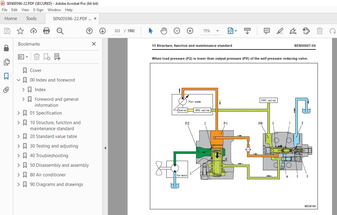
Self pressure reducing valve 319
Work equipment 327
Cylinder stay 328
Blade 330
Cutting edge, end bit 332
Ripper 334
Cab and its attachments 341
Cab mount + ROPS pin 342
ROPS cab 343
Air conditioner 344
Electrical system 347
Engine control 348
Engine control system 349
Deceleration potentiometer 350
Monitor system 352
Sensors 371
Palm command control system 374
KOMTRAX system 377
20 Standard value table 381
Standard service value table 381
Standard value table for engine 382
Standard value table for machine 383
30 Testing and adjusting 393
Testing and adjusting, Part 1 393
Tools for testing, adjusting, and troubleshooting 395
Measuring engine speed 399
Measuring intake air pressure (boost pressure) 401
Measuring exhaust temperature 402
Measuring exhaust gas color 404
Adjusting valve clearance 405
Measuring compression pressure 406
Measuring blow-by pressure 408
Measuring engine oil pressure 409
Testing EGR valve and bypass valve drive oil pressure 410
Handling fuel system parts 411
Releasing residual pressure from fuel system 411
Measuring fuel pressure 412
Measuring fuel return rate and fuel leakage 413
Bleeding air from fuel circuit 417
Measuring fuel circuit for leakage 419
Testing and adjusting alternator belt tension 420
Testing and adjusting air conditioner compressor belt tension 421
Measuring fan speed 422
Measuring fan circuit oil pressure 423
Bleeding air from fan pump 424
Adjusting fuel control dial and decelerator pedal 425
Testing and adjusting, Part 2 429
Measuring power train oil pressure 431
Adjusting transmission output shaft speed sensor 439
Simple test procedure for brake performance 440
Adjusting brake pedal 441
Adjusting parking brake lever 443
Emergency escape method when power train has trouble 445
Adjusting idler clearance 448
Testing and adjusting track shoe tension 449
Measuring and adjusting work equipment and HSS oil pressure 450
Bleeding air from work equipment and HSS pump 454
Measuring control circuit basic pressure 455
Measuring work equipment lock solenoid valve output pressure 456
Emergency operation method when work equipment has trouble 457
Measuring ripper pin puller solenoid valve output pressure 459
Testing parts which cause hydraulic drift of blade and ripper 460
Measuring internal leakage of work equipment cylinder 461
Releasing residual pressure from work equipment cylinder 462
Bleeding air from work equipment cylinder 462
Adjusting work equipment lock lever 463
Adjusting blade 464
Adjusting operator’s cab 466
Testing and adjusting, Part 3 471
Special functions of machine monitor (EMMS) 472
Testing and adjusting, Part 4 551
Handling of power supply circuit of engine controller 552
Preparation work for troubleshooting of electrical system 553
Pm Clinic 555
40 Troubleshooting 567
Failure code table and fuse locations 567
Failure codes table 568
Fuse locations 575
Information in troubleshooting table 579
General information on troubleshooting 583
Points to remember when troubleshooting 584
Sequence of events in troubleshooting 585
Check before troubleshooting 586
Classification and procedures for troubleshooting 587
Connection table for connector pin numbers 590
T-branch box and T-branch adapter table 626
Troubleshooting by failure and error codes, Part 1 631
Failure code [1500L0] 633
Failure code [15SAL1] 634
Failure code [15SALH] 636
Failure code [15SBL1] 638
Failure code [15SBLH] 640
Failure code [15SEL1] 642
Failure code [15SELH] 644
Failure code [15SFL1] 646
Failure code [15SFLH] 648
Failure code [15SGL1] 650
Failure code [15SGLH] 652
Failure code [15SJL1] 654
Failure code [15SJLH] 656
Failure code [2301L1] 658
Failure code [2301LH] 660
Failure code [2302L1] 662
Failure code [2302LH] 664
Failure code [7RFAKA] 666
Failure code [AA10NX] 668
Failure code [AB00MA] 670
Failure code [B@BAZG] 672
Failure code [B@BCNS] 673
Failure code [B@BCZK] 674
Failure code [B@CENS] 675
Failure code [B@HANS] 676
Troubleshooting by failure and error codes, Part 2 679
Failure code [CA111] 681
Failure code [CA115] 683
Failure code [CA122] 685
Failure code [CA123] 688
Failure code [CA131] 689
Failure code [CA132] 691
Failure code [CA135] 692
Failure code [CA141] 695
Failure code [CA144] 696
Failure code [CA145] 698
Failure code [CA153] 699
Failure code [CA154] 701
Failure code [CA187] 701
Failure code [CA221] 702
Failure code [CA222] 705
Failure code [CA227] 706
Failure code [CA234] 709
Failure code [CA238] 710
Failure code [CA263] 712
Failure code [CA265] 714
Failure code [CA271] 715
Failure code [CA272] 717
Failure code [CA273] 719
Failure code [CA274] 721
Failure code [CA322] 723
Failure code [CA323] 725
Failure code [CA324] 727
Failure code [CA325] 729
Failure code [CA331] 731
Failure code [CA332] 733
Failure code [CA342] 735
Failure code [CA351] 736
Failure code [CA352] 739
Failure code [CA386] 740
Failure code [CA441] 742
Failure code [CA442] 742
Failure code [CA449] 743
Failure code [CA451] 744
Failure code [CA452] 747
Failure code [CA553] 748
Failure code [CA554] 750
Failure code [CA559] 751
Failure code [CA689] 756
Troubleshooting by failure and error codes, Part 3 759
Failure code [CA731] 761
Failure code [CA757] 762
Failure code [CA778] 763
Failure code [CA1228] 766
Failure code [CA1625] 768
Failure code [CA1626] 769
Failure code [CA1627] 771
Failure code [CA1628] 772
Failure code [CA1629] 775
Failure code [CA1631] 776
Failure code [CA1632] 779
Failure code [CA1633] 780
Failure code [CA1642] 781
Failure code [CA1653] 782
Failure code [CA2185] 785
Failure code [CA2186] 787
Failure code [CA2249] 787
Failure code [CA2271] 788
Failure code [CA2272] 791
Failure code [CA2351] 792
Failure code [CA2352] 794
Failure code [CA2555] 795
Failure code [CA2556] 796
Failure code [D110KA] 798
Failure code [D110KB] 800
Failure code [D130KA] 802
Failure code [D130KB] 805
Failure code [D161KA] 807
Failure code [D161KB] 809
Failure code [D190KA] 811
Failure code [D190KB] 813
Failure code [D5ZKKX] 815
Failure code [DAFRKR] 817
Failure code [DAFRMC] 818
Failure code [DB2RKR] 825
Failure code [DB90KK] 830
Failure code [DB90KR] 833
Troubleshooting by failure and error codes, Part 4 835
Failure code [DB90KT] 837
Failure code [DB95KK] 838
Failure code [DB97KK] 840
Failure code [DB99KQ] 842
Failure code [DB9RKR] 844
Failure code [DBE0KK] 847
Failure code [DBE0KT] 849
Failure code [DBE5KK] 850
Failure code [DBE6KK] 853
Failure code [DBE9KQ] 855
Failure code [DD12KA] 857
Failure code [DD12KB] 859
Failure code [DD13KA] 861
Failure code [DD13KB] 863
Failure code [DD14KA] 865
Failure code [DD14KB] 867
Failure code [DDDDKA] 869
Failure code [DDDDKB] 871
Failure code [DDDDKX] 873
Failure code [DDN7KA] 874
Failure code [DDN7KB] 876
Failure code [DDN9KA] 878
Failure code [DDN9KB] 880
Failure code [DDNLKA] 882
Failure code [DDNLKB] 884
Failure code [DDTSL1] 886
Failure code [DDTSLH] 888
Troubleshooting by failure and error codes, Part 5 891
Failure code [DFA4KX] 893
Failure code [DFA4KZ] 893
Failure code [DFA4L8] 894
Failure code [DFA5KA] 895
Failure code [DFA5KB] 897
Failure code [DFA6KA] 899
Failure code [DFA6KB] 901
Failure code [DFA7KX] 903
Failure code [DFA7KZ] 903
Failure code [DFA7L8] 904
Failure code [DFA8KA] 905
Failure code [DFA8KB] 907
Failure code [DFA9KA] 909
Failure code [DFA9KB] 911
Failure code [DFAAKX] 913
Failure code [DFAAKZ] 913
Failure code [DFAAL8] 914
Failure code [DFABKA] 915
Failure code [DFABKB] 917
Failure code [DFACKA] 919
Failure code [DFACKB] 921
Failure code [DFADKX] 923
Failure code [DFADKZ] 923
Failure code [DFADL8] 924
Failure code [DFAEKA] 925
Failure code [DFAEKB] 927
Failure code [DFAFKA] 929
Failure code [DFAFKB] 931
Failure code [DGT1KA] 933
Failure code [DGT1KX] 935
Failure code [DH21KA] 937
Failure code [DH21KB] 940
Failure code [DHT5KA] 942
Failure code [DHT5KB] 944
Failure code [DHT7KA] 946
Failure code [DHT7KB] 948
Failure code [DK10KX] 950
Troubleshooting by failure and error codes, Part 6 953
Failure code [DK30KA] 955
Failure code [DK30KB] 958
Failure code [DK30KX] 960
Failure code [DK30KZ] 960
Failure code [DK30L8] 961
Failure code [DK31KA] 962
Failure code [DK31KB] 965
Failure code [DK40KA] 967
Failure code [DK40KB] 969
Failure code [DK55KX] 971
Failure code [DK55KZ] 971
Failure code [DK55L8] 972
Failure code [DK56KA] 973
Failure code [DK56KB] 976
Failure code [DK57KA] 978
Failure code [DK57KB] 981
Failure code [DKH1KA] 983
Failure code [DKH1KB] 985
Failure code [DLT3KA] 987
Failure code [DLT3KB] 989
Failure code [DW7BKA] 991
Failure code [DW7BKB] 993
Failure code [DWN1KA] 995
Failure code [DWN1KB] 997
Failure code [DWN1KY] 999
Failure code [DWN2KA] 1001
Failure code [DWN2KB] 1003
Failure code [DWN2KY] 1005
Failure code [DWN3KA] 1007
Failure code [DWN3KB] 1009
Failure code [DWN3KY] 1011
Failure code [DWN5KA] 1013
Failure code [DWN5KB] 1015
Failure code [DWN5KY] 1017
Failure code [DXA0KA] 1019
Failure code [DXA0KB] 1021
Failure code [DXA0KY] 1023
Failure code [DXH1KA] 1025
Failure code [DXH1KB] 1027
Failure code [DXH1KY] 1029
Failure code [DXH4KA] 1031
Troubleshooting by failure and error codes, Part 7 1035
Failure code [DXH4KB] 1038
Failure code [DXH4KY] 1040
Failure code [DXH5KA] 1042
Failure code [DXH5KB] 1044
Failure code [DXH5KY] 1046
Failure code [DXH6KA] 1048
Failure code [DXH6KB] 1050
Failure code [DXH6KY] 1052
Failure code [DXH7KA] 1054
Failure code [DXH7KB] 1056
Failure code [DXH7KY] 1058
Failure code [DXH8KA] 1060
Failure code [DXH8KB] 1062
Failure code [DXH8KY] 1064
Failure code [DXHBKA] 1066
Failure code [DXHBKB] 1068
Failure code [DXHBKY] 1070
Failure code [DXHCKA] 1072
Failure code [DXHCKB] 1074
Failure code [DXHCKY] 1076
Failure code [DXHRKA] 1078
Failure code [DXHRKB] 1080
Failure code [DXHRKY] 1082
Failure code [DXHSKA] 1084
Failure code [DXHSKB] 1086
Failure code [DXHSKY] 1088
Failure code [DXHTKA] 1090
Failure code [DXHTKB] 1092
Failure code [DXHTKY] 1094
Failure code [DXHUKA] 1096
Failure code [DXHUKB] 1098
Failure code [DXHUKY] 1100
Failure code [DXHWKA] 1102
Failure code [DXHWKB] 1104
Failure code [DXHWKY] 1106
Failure code [DXHXKA] 1108
Failure code [DXHXKB] 1110
Failure code [DXHXKY] 1112
Failure code [DXHYKA] 1114
Failure code [DXHYKB] 1116
Failure code [DXHYKY] 1118
Failure code [DXHZKA] 1120
Failure code [DXHZKB] 1122
Failure code [DXHZKY] 1124
Failure code [DXJ4KA] 1126
Failure code [DXJ4KB] 1128
Troubleshooting by failure and error codes, Part 8 1131
Failure code [DXJ8KA] 1132
Failure code [DXJ8KB] 1134
Failure code [DXJ8KY] 1136
Failure code [DXJ9KA] 1138
Failure code [DXJ9KB] 1140
Failure code [DXJ9KY] 1142
Failure code [DXJAKA] 1144
Failure code [DXJAKB] 1146
Failure code [DXJAKY] 1148
Failure code [DXJBKA] 1150
Failure code [DXJBKB] 1152
Failure code [DXJBKY] 1154
Troubleshooting of electrical system (E-mode) 1157
Information in troubleshooting table 1159
E-1 When starting switch turned ON, machine monitor displays nothing 1160
E-2 When starting switch turned ON (before starting engine), basic check item lights up 1163
E-3 Engine does not start (Engine does not turn) 1165
E-4 Preheater does not operate 1168
E-5 Precaution item lights up while engine is running 1172
E-6 Emergency stop item lights up while engine is running 1174
E-7 Engine coolant temperature gauge does not indicate normally 1178
E-8 Fuel level gauge does not indicate normally 1180
E-9 Power train oil temperature gauge (multi-gauge) does not indicate normally 1183
E-10 Hydraulic temperature gauge (multi-gauge) does not indicate normally 1185
E-11 Contents of display by machine monitor are different from applicable machine 1188
E-12 Machine monitor does not display some items 1188
E-13 Function switch does not work 1189
E-14 Operation mode does not change 1190
E-15 Gearshift mode does not change 1191
E-16 Customize function does not operate normally 1192
E-17 Customize memory function does not normally 1193
E-18 Float mode does not change 1194
E-19 Alarm buzzer cannot be stopped 1195
E-20 Air conditioner does not operate normally (including air conditioner fault history) 1196
E-21 When starting switch is turned OFF, service meter is not displayed 1217
E-22 Machine monitor cannot be set in service mode 1217
E-23 Ripper pin puller cylinder does not operate 1218
E-24 Backup alarm does not sound or does not stop 1220
E-25 Headlamp, rear lamp, and ripper point lamp do not light up 1222
E-26 Windshield wiper and window washer do not operate 1228
E-27 KOMTRAX system does not operate normally 1256
Troubleshooting of hydraulic and mechanical system (H-mode) 1259
Information in troubleshooting table 1261
H-1 Power is low (Drawbar pull is low) 1262
H-2 Machine does not travel (at 2nd or 3rd gear speed) 1264
H-3 Machine does not start at any gear speed 1266
H-4 Machine can travel only forward or in reverse 1268
H-5 When gear speed or travel direction is changed, time lag is large 1270
H-6 Machine cannot be steered (Machine does not turn right or left) 1272
H-7 Steering speed or steering force is low 1273
H-8 Brake does not work 1274
H-9 Power train oil is overheated 1275
H-10 Abnormal sound comes out from around HSS pump or HSS motor 1277
H-11 Speed of all work equipment is low 1279
H-12 No work equipment moves 1281
H-13 Blade lift speed or power is low 1283
H-14 Blade tilt speed or power is low 1285
H-15 Ripper lift speed or power is low 1286
H-16 Ripper tilt speed or power is low 1288
H-17 Hydraulic drift of blade lift is large 1290
H-18 Hydraulic drift of blade tilt is large 1291
H-19 Hydraulic drift of ripper lift is large 1292
H-20 Ripper pin puller cylinder does not operate 1293
H-21 Blade does not pitch 1294
H-22 Abnormal sound comes out from around work equipment pump 1295
H-23 Fan speed is abnormal (Abnormally large sound or vibration of fan) 1296
Troubleshooting of engine (S-mode) 1299
Method of using troubleshooting chart 1301
S-1 Starting performance of engine is poor 1304
S-2 Engine does not start 1306
S-3 Engine does not pick up smoothly 1310
S-4 Engine stops during operation 1311
S-5 Engine does not rotate smoothly 1312
S-6 Engine lack output (or lacks power) 1313
S-7 Exhaust gas is black (incomplete combustion) 1314
S-8 Oil consumption is excessive (or exhaust gas is blue) 1316
S-9 Oil becomes dirty quickly 1317
S-10 Fuel consumption is excessive 1318
S-11 Oil is in coolant (or coolant spurts back or coolant level goes down) 1319
S-12 Oil pressure drops 1320
S-13 Oil level rises (Entry of coolant or fuel) 1322
S-14 Coolant temperature becomes too high (Overheating) 1324
S-15 Abnormal noise is made 1325
S-16 Vibration is excessive 1326
50 Disassembly and assembly 1329
General information on disassembly and assembly 1329
How to read this manual 1330
Coating materials list 1332
Special tool list 1335
Sketches of special tools 1344
Engine and cooling system 1359
Removal and installation of fuel supply pump assembly 1360
Removal and installation of fuel injector assembly 1367
Removal and installation of cylinder head assembly 1375
Removal and installation of radiator assembly 1396
Removal and installation of aftercooler assembly 1402
Removal and installation of engine assembly 1409
Removal and installation of engine hood assembly 1418
Removal and installation of engine front seal 1422
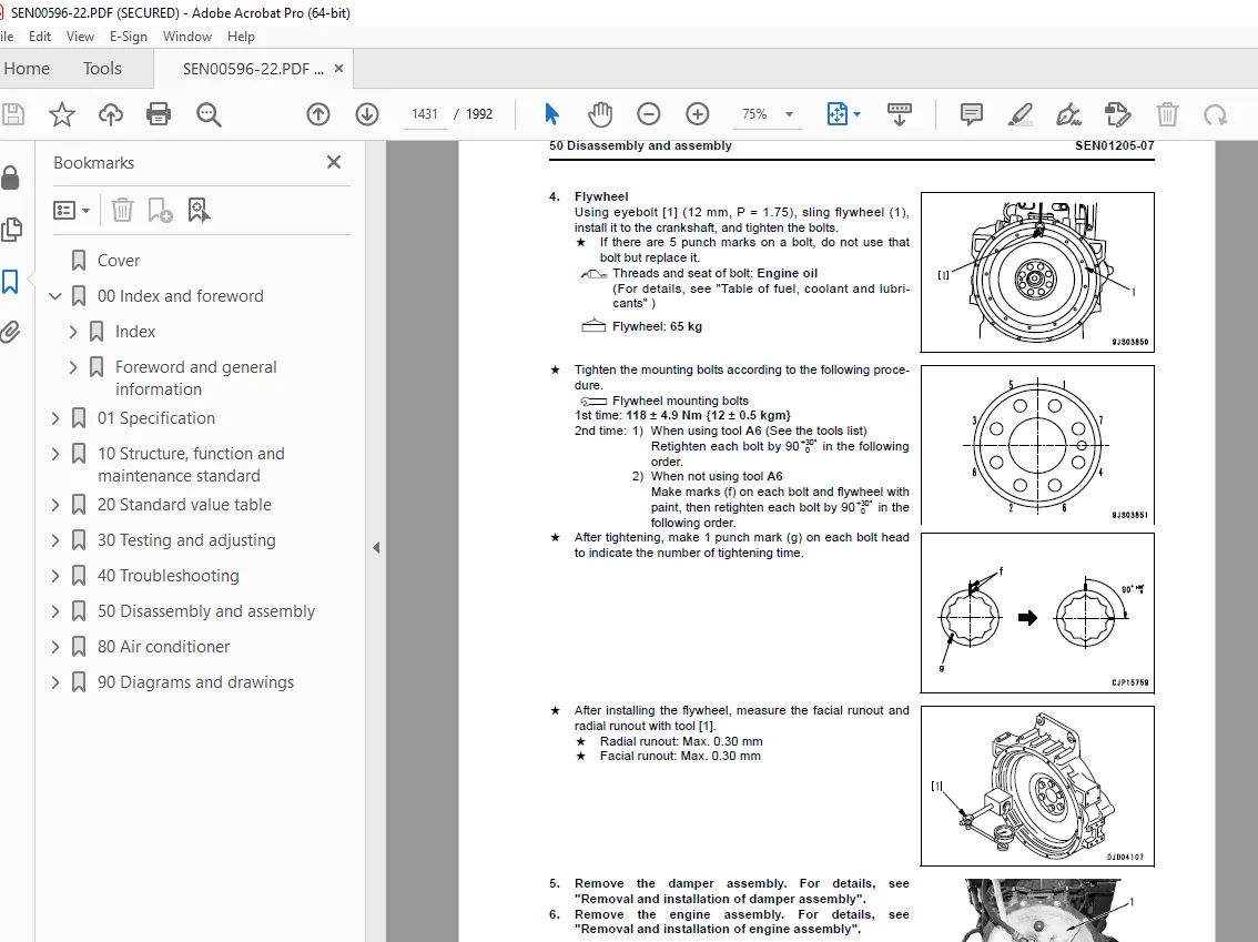
Removal and installation of engine rear seal 1426
Removal and installation of fuel tank assembly 1432
Removal and installation of cooling fan drive assembly 1437
Removal and installation of fan motor assembly 1441
Power train, Part 1 1445
Removal and installation of damper assembly 1446
Disassembly and assembly of damper assembly 1451
Removal and installation of power train unit assembly 1457
Disconnection and connection of power train unit assembly 1470
Power train, Part 2 1477
Disassembly and assembly of PTO assembly 1478
Disassembly and assembly of torque converter assembly 1487
Disassembly and assembly of transmission assembly 1498
Disassembly and assembly of HSS case assembly 1517
Removal and installation of HSS motor assembly 1537
Power train, Part 3 1541
Removal and installation of final drive assembly 1542
Disassembly and assembly of final drive assembly 1549
Undercarriage and frame 1567
Removal and installation of track frame assembly 1569
Removal and installation of idler assembly 1576
Disassembly and assembly of idler assembly 1581
Removal and installation of recoil spring assembly 1586
Disassembly and assembly of recoil spring assembly 1589
Removal and installation of track roller assembly 1594
Disassembly and assembly of track roller assembly 1598
Removal and installation of 1st bogie assembly 1601
Removal and installation of 2nd, 3rd, and 4th bogie assemblies 1611
Disassembly and assembly of bogie assembly 1620
Removal and installation of carrier roller assembly 1623
Disassembly and assembly of carrier roller assembly 1626
Removal and installation of pivot shaft assembly 1631
Separation and connection of track shoe assembly 1634
General disassembly and assembly of track shoe 1639
Disassembly and assembly of 1 link in field 1652
Disassembly and assembly of master link 1657
Removal and installation of equalizer bar assembly 1661
Disassembly and assembly of equalizer bar assembly 1666
Removal and installation of segment teeth 1668
Hydraulic system 1673
Removal and installation of hydraulic tank assembly 1674
Removal and installation of hydraulic pump assembly 1680
Disassembly and assembly of hydraulic cylinder assembly 1691
Work equipment 1703
Removal and installation of blade assembly 1704
Disassembly and assembly of multi-shank ripper 1708
Cab and its attachments 1713
Removal and installation of operator’s cab assembly 1714
Removal and installation of operator’s cab glass (adhered window glass) 1719
Removal and installation of operator’s cab and floor frame assembly 1729
Removal and installation of air conditioner unit assembly 1738
Electrical system 1747
Removal and installation of engine controller assembly 1748
Removal and installation of power train controller 1751
Removal and installation of work equipment controller assembly 1754
80 Air conditioner 1757
Structure, function, testing, adjusting, and troubleshooting 1757
Structure and function 1759
Air conditioner component 1759
Configuration and function of refrigerating cycle 1760
Outline of refrigerating cycle 1761
Air conditioner unit 1763
Functions of major components in the air conditioner unit 1765
Control plate 1767
Compressor 1769
Condenser 1770
Receiver drier 1771
Testing, adjusting and troubleshooting 1773
Caution about refrigerant 1773
Troubleshooting procedure 1774
Basic flow of troubleshooting 1774
Block diagram 1775
Circuit diagram and arrangement of connector pins 1776
Detail of air conditioner unit 1778
Part and connector locations 1780
Testing air leakage (duct) 1787
Testing with self-diagnosis function 1789
Testing temperature control 1792
Testing vent (mode) changeover 1795
Testing Recirc/Fresh changeover 1798
Testing inner sensor 1800
Testing evaporator temperature sensor 1801
Testing sunlight sensor 1804
Testing (dual) pressure switch for refrigerant 1805
Testing relays and diodes 1807
Troubleshooting chart 1 1809
Troubleshooting chart 2 1810
Troubleshooting for electrical system (E mode) 1813
E-1 Power supply system (Air conditioner does not operate) 1814
E-2 Compressor system (Air is not cooled) 1818
E-3 Blower motor system (No air comes out or air flow is abnormal) 1822
E-4 Temperature cannot be controlled 1828
E-5 Vent (mode) cannot be changed over 1831
E-6 Recirc/Fresh air cannot be changed over 1834
Troubleshooting with gauge pressure 1837
Connection of service tool 1839
Precautions for connecting air conditioner piping 1840
Handling of compressor oil 1841
1 Control of compressor oil 1841
2 Adding of compressor oil 1841
3 Compressor replacement 1842
4 Applying compressor oil for O-ring 1842
90 Diagrams and drawings 1845
Hydraulic diagrams and drawings 1845
Power train hydraulic circuit diagram 1845
Hydraulic circuit diagram (1/2) Serial No : 80001 to 80806 1849
Hydraulic circuit diagram (2/2) Serial No : 80001 to 80806 1851
Hydraulic circuit diagram (1/2) Serial No : 80807 and up 1853
Hydraulic circuit diagram (2/2) Serial No : 80807 and up 1855
Electrical diagrams and drawings 1859
Electrical circuit diagram (1/12) 1861
Electrical circuit diagram (2/12) 1863
Electrical circuit diagram (3/12) 1865
Electrical circuit diagram (4/12) 1867
Electrical circuit diagram (5/12) 1869
Electrical circuit diagram (6/12) 1871
Electrical circuit diagram (7/12) 1873
Electrical circuit diagram (8/12) 1875
Electrical circuit diagram (9/12) 1877
Electrical circuit diagram (10/12) 1879
Electrical circuit diagram (11/12) 1881
Electrical circuit diagram (12/12) 1883
Electrical circuit diagram for inside cab 1885
Connector/electrical wiring connection table 1887
Connectors table and arrangement drawing 1951
Wiring harness diagram (1/19) 1953
Wiring harness diagram (2/19) 1955
Wiring harness diagram (3/19) 1957
Wiring harness diagram (4/19) 1959
Wiring harness diagram (5/19) 1961
Wiring harness diagram (6/19) 1963
Wiring harness diagram (7/19) 1965
Wiring harness diagram (8/19) 1967
Wiring harness diagram (9/19) 1969
Wiring harness diagram (10/19) 1971
Wiring harness diagram (11/19) 1973
Wiring harness diagram (12/19) 1975
Wiring harness diagram (13/19) 1977
Wiring harness diagram (14/19) 1979
Wiring harness diagram (15/19) 1981
Wiring harness diagram (16/19) 1983
Wiring harness diagram (17/19) 1985
Wiring harness diagram (18/19) 1987
Wiring harness diagram (19/19) 1989
DESCRIPTION:
Komatsu D155AX-6 Bulldozer Shop Manual SEN00596-22 – PDF DOWNLOAD
SERIAL NUMBERS 80001 and up
How to read the shop manual
1. Composition of shop manual
This shop manual contains the necessary technical information for services performed in a workshop.
For ease of understanding, the manual is divided into the following sections.
00. Index and foreword
This section explains the shop manuals list, table of contents, safety, and basic information.
01. Specification
This section explains the specifications of the machine.
10. Structure, function and maintenance standard
This section explains the structure, function, and maintenance standard values of each component.
The structure and function sub-section explains the structure and function of each component. It
serves not only to give an understanding of the structure, but also serves as reference material for
troubleshooting. The maintenance standard sub-section explains the criteria and remedies for disassembly
and service.
20. Standard value table
This section explains the standard values for new machine and judgement criteria for testing,
adjusting, and troubleshooting. This standard value table is used to check the standard values in
testing and adjusting and to judge parts in troubleshooting.
30. Testing and adjusting
This section explains measuring instruments and measuring methods for testing and adjusting, and
method of adjusting each part. The standard values and judgement criteria for testing and adjusting
are explained in Testing and adjusting.
40. Troubleshooting
This section explains how to find out failed parts and how to repair them. The troubleshooting is
divided by failure modes. The “S mode” of the troubleshooting related to the engine may be also
explained in the Chassis volume and Engine volume. In this case, see the Chassis volume.
50. Disassembly and assembly
This section explains the special tools and procedures for removing, installing, disassembling, and
assembling each component, as well as precautions for them. In addition, tightening torque and
quantity and weight of coating material, oil, grease, and coolant necessary for the work are also
explained.
80. Appendix
The section explains the equipment which can not be included in the other sections. This section
explains the structure, function, testing, adjusting, and troubleshooting of the equipment.
90. Diagrams and drawings (chassis volume)/Repair and replacement of parts (engine volume)
q Chassis volume
This section gives hydraulic circuit diagrams and electrical circuit diagrams.
q Engine volume
This section explains the method of reproducing, repairing, and replacing parts.
S.V 29/12/24


