Description
KOMATSU D355A- I BULLDOZER Shop Manual D355A.1-BE3 – PDF DOWNLOAD
FILE DETAILS:
KOMATSU D355A- I BULLDOZER Shop Manual D355A.1-BE3 – PDF DOWNLOAD
Language : English
Pages :258
Downloadable : Yes
File Type : PDF
DESCRIPTION:
KOMATSU D355A- I BULLDOZER Shop Manual D355A.1-BE3 – PDF DOWNLOAD
D355A.1-BE3
GENERAL PRECAUTIONS
• Before attempting to disassemble, determine the cause of the trouble by systematically checking and analysing the symptoms. Needless disassembly will not only hinder trouble shooting, but will also result in looses from need
• less replacement parts and man-hour costs.
• During disassembly, carefully check every sliding part for any signs of seizing, interference or con• tact, since these may reveal hidden faults which could be the cause of the actual trouble.
• Unless major disassembly, based on definite rea sons is to be made, the related parts should be first briefly inspected, and disassembly started after confidence in the operation is established.
• Thoroughly clean the part of the machine to be disassembled, before attempting to disassemble.
• Proceed with the disassembly by confirming, the fitting conditions of the relative parts; their posi tions fore-and-aft. left-and-right and upper-and -lo w er, and the proper sequence of their removal.
• When draining lubricating oil and hydraulic fluid, take note of their viscosity, color and state of con tamination. Observation of used oil and fluid, often provides clues to the wear condition of the lubrica ted parts (specially in regards to gears and bearings).
• Put match marks across mating joints where re quired, before separating parts, and identify each part by scribe marks. The parts should be clearly marked to prevent confusion at the time of assemb ly.
• For disassembly of certain designated parts, only use the special tool prescribed for this purpose.
• When a part, after removal of fastening nuts and bolts, is still found to be unremovable, never force the part, but carefully check for the cause of the tightness.
• When looseness exists between force-fitted or taper fitted parts, check both of the mating surfaces for damage or wear. Repair or replace the part(s) if necessary.
• When removing a control-link assembly, be careful to maintain the original adjustment of the length of the rods unless any re-adjustment is necessary . Check the original length of each rod and record it before removal of the link assembly, ii it is neces sary to remove the rod-end for disassembly.
• Maintain disassembled parts in good order for stor age, special care being paid not to confuse any similar parts with each other. If it is unnecessary to store a part separated from its assembly, keep the part fitted in its original place. Take care that the standard parts such as bolts and nuts should be properly stored with re ference to the location and quantities that are to be used.
• Wash disassembled parts clean, neatly arrange the parts for each assembly, and keep in storage, free from dust and dirt.
• Use of two vessels filled with washing oil, one for washing dirty parts and the other for rinsing them, is recommended for cleaning more effectively.
• Keep each set of shims stacked in its original ar rangement so that the same clearances before dis assembly can be obtained when the machine is re assembled.
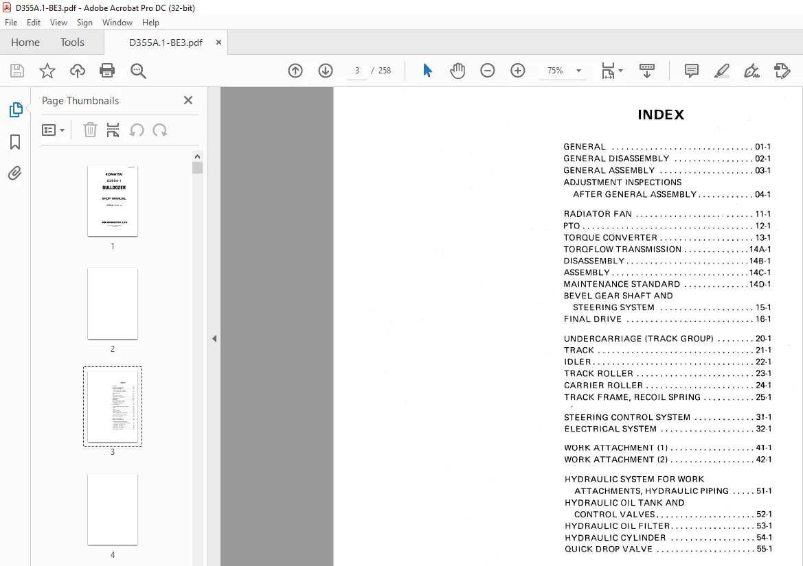
TABLE OF CONTENTS:
KOMATSU D355A- I BULLDOZER Shop Manual D355A.1-BE3 – PDF DOWNLOAD
D355A.1-BE3
GENERAL 01-1
GENERAL DISASSEMBLY 02-1
GENERAL ASSEMBLY 03-1
ADJUSTMENT INSPECTIONS
AFTER GENERAL ASSEMBLY 04-1
RADIATOR FAN 11-1
PTO 12-1
TORQUE CONVERTER 13-1
TOROFLOW TRANSMISSION 14A-1 DISASSEMBLY 148-1
ASSEMBLY 14C-1 MAINTENANCE STANDARD 140-1
BEVEL GEAR SHAFT AND
STEERING SYSTEM 15-1
F IN AL DR IVE 16-1
UNDERCARRIAGE (TRACK GROUP) 20-1
TRACK 21-1
IDLER 22-1
TRACK ROLLER 23-1
CARRIER ROLLER 24-1
TRACK FRAME, RECOIL SPRING 25-1
STEERING CONTROL SYSTEM 31-1
ELECTRICAL SYSTEM 32-1
WORK ATTACHMENT (1) 41-1
WORK ATTACHMENT (2) 42-1
HYDRAULIC SYSTEM FOR WORK ATTACHMENTS, HYDRAULIC PIPING 51-1
HYDRAULIC OIL TANK AND
CONTROL VALVES 52-1
HYDRAULIC OIL FILTER 53-1
HYDRAULIC CYLINDER 54-1
QUICK DROP VALVE 55-1
IMAGES PREVIEW OF THE MANUAL:


S.M 18/12/24