Komatsu D375A-6 Bulldozer Shop Manual SEN06484-10 PDF
$39.95
Komatsu D375A-6 Bulldozer Shop Manual SEN06484-10 – PDF DOWNLOAD
SERIAL NUMBERS 60001 and up
Description
Komatsu D375A-6 Bulldozer Shop Manual SEN06484-10 – PDF DOWNLOAD
FILE DETAILS:
Komatsu D375A-6 Bulldozer Shop Manual SEN06484-10 – PDF DOWNLOAD
Language : English
Pages : 1792
Downloadable : Yes
File Type : PDF
IMAGES PREVIEW OF THE MANUAL:
TABLE OF CONTENTS:
Komatsu D375A-6 Bulldozer Shop Manual SEN06484-10 – PDF DOWNLOAD
SERIAL NUMBERS 60001 and up
COVER 1
00 Index and foreword 3
Table of contents 4
Forword and general information 15
Safety notice 15
How to read the shop manual 20
Explanation of terms for maintenance standard 22
Handling of electric equipment and hydraulic components 24
Handling of connectors newly used for engines 33
How to read electric wire code 36
Precautions when carrying out work 39
Method of disassembling and connecting push-pull type coupler 42
Standard tightening torque table 45
List of Abbreviation 49
Conversion table 53
01 Specification 59
Contents 60
Specification and technical data 61
Specification drawing 61
Specifications 62
Weight table 67
Table of fuel, coolant and lubricants 69
10 Structure and function 71
Contents 72
Engine and cooling system 74
Cooling system 74
Cooling fan pump 76
Cooling fan motor 96
Power train 102
Power train 102
Overall drawing of power train unit 104
Power train hydraulic equipment arrangement drawing 106
Damper and universal joint 108
Torque converter and PTO 110
Torque converter control valve 116
Main relief valve and torque converter relief valve 118
Lockup clutch ECMV and stator clutch ECMV 120
Scavenging pump 125
Transmission control 126
PCCS lever 128
Transmission 132
Transmission ECMV 146
Transmission lubrication relief valve 151
Steering and brake control 152
Transfer unit, bevel gear shaft and steering 154
Steering control valve 160
Steering clutch ECMV and Steering brake ECMV 162
Parking brake valve 170
Sudden stop prevention valve 171
Final drive 173
Undercarriage and frame 178
Track frame 178
Idler cushion 180
Track roller bogie 181
Main frame 182
Suspension 184
Hydraulic system 187
Work equipment hydraulic piping diagram 187
PPC control piping diagram 191
Work equipment control 192
Hydraulic tank 194
Accumulator 196
PPC lock valve 197
PPC valve 199
Piston valve 210
Quick drop valve 211
Pin puller switch 212
Pin puller solenoid valve 213
Blade control lever (only for the machine with dual tilt specification) 215
Work equipment pump 216
Control valve 228
Self-pressure reducing valve 252
Work equipment 259
Cylinder stay 259
Cab 260
Cab mount 260
Cab 261
Electrical system 264
Engine control 264
Engine control system 265
CRI engine control system 274
Monitor system 276
Machine monitor 278
Lamp system 296
Engine preheat (electrical intake air heater) control 297
Palm command control system 298
Sensor 301
Vehicle health monitoring system (VHMS) 308
Electric warming and preheating system 314
Pre-lubrication system 324
20 Standard value table 329
Contents 330
Standard service value table 331
Standard value table for engine 331
Standard value table for machine 332
30 Testing and adjusting 341
Contents 342
Tools for testing, adjusting and troubleshooting 344
Diagnosis equipment list 344
Engine and cooling system 346
Testing engine speed 346
Testing intake air pressure (boost pressure) 349
Testing exhaust temperature 351
Testing exhaust gas color 354
Adjusting valve clearance 356
Measuring compression pressure 358
Testing blow-by pressure 361
Testing engine oil pressure 363
Testing EGR valve drive oil pressure 364
Handling of fuel system devices 366
Releasing residual pressure from fuel system 367
Testing fuel pressure 368
Handling of reduced cylinder mode operation 369
Handling of no injection cranking operation 369
Testing leakage from pressure limiter and return rate from injector 370
Bleeding air from fuel circuit 373
Testing fuel circuit for leakage 375
Replacing and adjusting alternator and air conditioner compressor belt 376
Measuring fan speed 377
Testing fan circuit oil pressure 378
Bleeding air from fan pump 379
Adjusting fuel control dial and decelerator pedal 380
Power train 382
Testing power train oil pressure 382
Adjusting transmission output speed sensor 398
Simple test procedure for brake performance 399
Adjusting brake pedal and parking brake lever 400
Adjusting position of pccs lever console 403
Emergency escape method when there is failure in power train 404
Undercarriage and frame 406
Inspecting wear of sprocket 406
Testing and adjusting track shoe tension 407
Hydraulic system 408
Testing and adjusting work equipment oil pressure 408
Testing control circuit main pressure 411
Testing PPC valve output pressure 412
Adjusting play of PPC valve 414
Testing output pressure of ripper pin-puller solenoid valve 415
Checking location of cause of hydraulic drift of blade and ripper 416
Testing leakage inside work equipment cylinder 417
Releasing remaining pressure in work equipment cylinders 418
Bleeding air from work equipment cylinders 418
Adjusting ripper lever position 419
Work equipment 420
Adjusting work equipment lock lever 420
Adjusting blade 421
Cab and its attachments 423
Testing and adjusting operator’s cab 423
Testing and adjusting operator’s seat isolator 428
Electrical system 432
Special functions of machine monitor (EMMS) 432
Handling of voltage circuit of engine controller 493
Adjustment method when controller has been replaced 494
Preparation work for troubleshooting for electrical equipment system 498
Inspection procedure of diode 502
Handling of optional devices 503
Request for opening ORBCOMM terminal 504
Initialization procedures for VHMS controller 506
Using method of KOMTRAX functions of ORBCOMM terminal 521
Precautions for replacing VHMS controller 524
Pm Clinic 530
Pm Clinic service 530
40 Troubleshooting 541
Table of contents 542
General information on troubleshooting 549
Points to remember when troubleshooting 549
Sequence of events in troubleshooting 550
Checks before troubleshooting 551
Classification and procedures for troubleshooting 576
Failure codes table 579
Classification and procedures for troubleshooting numbers 585
Information in troubleshooting table 587
Troubleshooting method for disconnecting wiring harness of pressure sensor system 589
Connection table for connector pin numbers 592
T-branch box and T-branch adapter table 628
Connector list and layout 631
Fuse locations table 645
Troubleshooting by failurecode 649
Failure code [1380MW] Lock up clutch: Slip 649
Failure code [1500L0] Transmission clutch: Abnormal 650
Failure code [15E0MW] Transmission clutch: Slip 651
Failure code [15SAL1] Forward clutch: Fill high 652
Failure code [15SALH] Forward clutch: Fill Low 654
Failure code [15SBL1] Reverse clutch: Fill high 656
Failure code [15SBLH] Reverse clutch: Fill Low 658
Failure code [15SEL1] Speed 1st clutch: Fill high 660
Failure code [15SELH] Speed 1st clutch: Fill Low 662
Failure code [15SFL1] Speed 2nd clutch: Fill high 664
Failure code [15SFLH] Speed 2nd clutch: Fill Low 666
Failure code [15SGL1] Speed 3rd clutch: Fill high 668
Failure code [15SGLH] Speed 3rd clutch: Fill Low 670
Failure code [15SJL1] L/U: Fill high 672
Failure code [15SJLH] L/U: Fill low 674
Failure code [1800MW] P/T clutch: Slip 676
Failure code [2201L1] Right clutch: Fill high 678
Failure code [2201LH] Right clutch: Fill low 680
Failure code [2202L1] Left clutch: Fill high 682
Failure code [2202LH] Left clutch: Fill low 684
Failure code [2300NR] Brake Themal Load Abnormality 686
Failure code [2301L1] Right brake: Fill high 688
Failure code [2301LH] Right brake: Fill low 690
Failure code [2301NR] Steering Brake RH Themal Load Abnormality 692
Failure code [2302L1] Left brake: Fill high 694
Failure code [2302LH] Left brake: Fill low 696
Failure code [2302NR] Steering Brake LH Themal Load Abnormality 698
Failure code [7RFAKA] ECM ACC CUT RELAY: Disconnection 700
Failure code [7RFAKB] ECM ACC CUT RELAY: Short circuit 702
Failure code [AA10NX] Air Cleaner Clogging 704
Failure code [AB00MA] Battery Charge Abnormal 706
Failure code [B@BAZG] Eng Oil Press Low 707
Failure code [B@BAZK] Eng Oil Level Low 708
Failure code [B@BCNS] Eng Water Overheat 709
Failure code [B@BCZK] Eng Water Level Low 709
Failure code [B@CENS] T/C Oil Overheat 710
Failure code [B@HANS] Hyd Oil Overheat 711
Failure code [B@HAZK] Hyd Oil Level Low 712
Failure code [CA111] ECM Critical Internal Failure 714
Failure code [CA115] Eng Ne and Bkup Speed Sens Error 716
Failure code [CA122] Chg Air Press Sensor High Error 718
Failure code [CA123] Chg Air Press Sensor Low Error 720
Failure code [CA131] Throttle Sensor High Error 722
Failure code [CA132] Throttle Sensor Low Error 724
Failure code [CA135] Eng Oil Press Sensor High Error 726
Failure code [CA141] Eng Oil Press Sensor Low Error 728
Failure code [CA144] Coolant Temp Sens High Error 730
Failure code [CA145] Coolant Temp Sens Low Error 732
Failure code [CA153] Chg Air Temp Sensor High Error 734
Failure code [CA154] Chg Air Temp Sensor Low Error 736
Failure code [CA187] Sens Supply 2 Volt Low Error 738
Failure code [CA212] Eng Oil Temp Sensor High Error 740
Failure code [CA213] Eng Oil Temp Sensor Low Error 742
Failure code [CA221] Ambient Press Sens High Error 744
Failure code [CA222] Ambient Press Sens Low Error 746
Failure code [CA227] Sens Supply 2 Volt High Error 748
Failure code [CA234] Eng Overspeed 749
Failure code [CA238] Ne Speed Sens Supply Volt Error 750
Failure code [CA263] Fuel Temp Sensor High Error 752
Failure code [CA265] Fuel Temp Sensor Low Error 754
Failure code [CA271] IMV/PCV1 Short Error 756
Failure code [CA272] IMV/PCV1 Open Error 757
Failure code [CA273] PCV2 Short Error 758
Failure code [CA274] PCV2 Open Error 759
Failure code [CA322] Inj #1 (L#1) Open/Short Error 760
Failure code [CA323] Inj #5 (L#5) Open/Short Error 762
Failure code [CA324] Inj #3 (L#3) Open/Short Error 764
Failure code [CA325] Inj #6 (L#6) Open/Short Error 766
Failure code [CA331] Inj #2 (L#2) Open/Short Error 768
Failure code [CA332] Inj #4 (L#4) Open/Short Error 770
Failure code [CA342] Calibration Code Incompatibility 772
Failure code [CA351] Injectors Drive Circuit Error 773
Failure code [CA352] Sens Supply 1 Volt Low Error 774
Failure code [CA386] Sens Supply 1 Volt High Error 776
Failure code [CA441] Battery Voltage Low Error 777
Failure code [CA442] Battery Voltage High Error 778
Failure code [CA449] Rail Press Very High Error 779
Failure code [CA451] Rail Press Sensor High Error 780
Failure code [CA452] Rail Press Sensor Low Error 782
Failure code [CA553] Rail Press High Error 784
Failure code [CA554] Rail Press Sensor In Range Error 785
Failure code [CA559] Rail Press Low Error 786
Failure code [CA689] Eng Ne Speed Sensor Error 790
Failure code [CA731] Eng Bkup Speed Sens Phase Error 792
Failure code [CA757] All Continuous Data Lost Error 793
Failure code [CA778] Eng Bkup Speed Sensor Error 794
Failure code [CA1228] EGR Valve Servo Error 1 796
Failure code [CA1625] EGR Valve Servo Error 2 797
Failure code [CA1633] KOMNET Datalink Timeout Error 798
Failure code [CA2185] Throt Sens Sup Volt High Error 799
Failure code [CA2186] Throt Sens Sup Volt Low Error 800
Failure code [CA2249] Rail Press Very Low Error 801
Failure code [CA2271] EGR Valve Pos Sens High Error 802
Failure code [CA2272] EGR Valve Pos Sens Low Error 804
Failure code [CA2351] EGR Valve Sol Current High Error 806
Failure code [CA2352] EGR Valve Sol Current Low Error 808
Failure code [D110KB] Battery Relay: Drive Short Circuit 810
Failure code [D130KA] Neutral relay: Disconnection 812
Failure code [D130KB] Neutral relay: Short circuit 814
Failure code [D161KA] Back-up alarm releay: Disconnection 816
Failure code [D161KB] Back-up alarm releay: Short circuit 818
Failure code [D182KZ] Preheater Relay Abnormality 820
Failure code [D190KA] ACC signal relay: Disconnection 822
Failure code [D190KB] ACC signal relay: Short circuit 824
Failure code [D1EFKA] Pre lub motor relay: Disconnection 826
Failure code [D1EFKB] Pre lub motor relay: Short circuit 828
Failure code [DAFRKR] Monitor: Can communication lost (PT) 830
Failure code [dAFRKR] Monitor: CAN communication lost (WE) 831
Failure code [DAFRMC] CAN Discon (Monitor Detected) 832
Failure code [DB2RKR] ENG cont : Can communication lost (PT) 837
Failure code [dB2RKR] ENG controller: CAN communication lost (WE) 840
Failure code [DB90KT] WE controller: Abnormality in controller 841
Failure code [DB91KK] WE controller: Source voltage reduction 842
Failure code [DB92KK] WE controller: Output voltage reduction 844
Failure code [DB97KK] WE cont : Sensor voltage 5 V (2) reduction 846
Failure code [DB99KQ] WE controller: Type select signal 848
Failure code [DB9RKR] WE controller: Can communication lost (PT) 849
Failure code [DBB0KK] VHMS controller:Source voltage reduction 852
Failure code [DBB0KQ] VHMS connector connection abnormality 854
Failure code [DBB3KK] VHMS controller: Source voltage reduction 855
Failure code [DBB5KP] VHMS: Output sensor1 voltage reduction 858
Failure code [DBB6KP] VHMS:Output sensor2 voltage reduction 860
Failure code [DBB7KP] VHMS:Output sensor3 voltage reduction 862
Failure code [DBBQKR] PT cont : Can communication lost (VHMS) 863
Failure code [DBE0KT] PT controller: Abnormality in controller 863
Failure code [DBE1KK] PT controller: Source voltage reduction 864
Failure code [DBE2KK] PT controller: Output voltage reduction 866
Failure code [DBE5KK] PT cont : Sensor voltage 5 V (1) reduction 868
Failure code [DBE6KK] PT cont : Sensor voltage 24V reduction 870
Failure code [DBE7KK] PT cont : Sensor voltage 5 V reduction 872
Failure code [DBE9KQ] PT controller: Type select signal 874
Failure code [DBERKR] PT controller: Can communication lost (WE) 875
Failure code [DD12KA] Shift up Sw: Disconnection 878
Failure code [DD12KB] Shift up Sw: Short circuit 880
Failure code [DD13KA] Shift down Sw: Disconnection 882
Failure code [DD13KB] Shift down Sw: Short circuit 884
Failure code [DD14KA] Parking lever Sw: Dissconnection 886
Failure code [DD14KB] Parking lever Sw: Short circuit 888
Failure code [DDB9L4] Reverse SW Signal disagreement 890
Failure code [DDE2KA] Pre lub oil press sw: Disconnection 892
Failure code [DDK3L4] Forward SW Signal disagreement 894
Failure code [DDK5KA] Shift switch disconnection 896
Failure code [DDK5KB] Shift switch short circuit 898
Failure code [DDN2LD] Blade tilt RH pressure SW abnormality 900
Failure code [DDN3LD] Blade tilt LH pressure SW abnormality 902
Failure code [DDN7KA] WEQ Knob Sw (down): Disconnection 904
Failure code [DDN7KB] WEQ Knob Sw (down): Short circuit 906
Failure code [DDN9KA] WEQ Knob Sw (up): Disconnection 908
Failure code [DDN9KB] WEQ Knob Sw (up): Short circuit 910
Failure code [DDNALD] Blade lift up pressure SW abnormality 912
Failure code [DDNBLD] Ripper lift up pressure SW abnormality 914
Failure code [DDNCLD] Ripper lift down pressure SW abnormality 916
Failure code [DDNDLD] Ripper tilt in pressure SW abnormality 918
Failure code [DDNELD] Ripper tilt back pressure SW abnormality 920
Failure code [DDNFLD] Blade lift down pressure SW abnormality 922
Failure code [DDNLKA] Weq lock Sw: Disconnection 924
Failure code [DDNLKB] Weq lock Sw: Short circuit 926
Failure code [DDT5KA] Neutral switch disconnection 928
Failure code [DDT5KB] Neutral switch short circuit 930
Failure code [DDT5KQ] Lever SPEC selection signal disagreement 932
Failure code [DDTSL1] S/C: Fill high 934
Failure code [DDTSLH] S/C: Fill low 936
Failure code [DGE5KX] Ambient temp sensor abnormality 938
Failure code [DGS1KX] Hyd oil temp: signal abnormal 940
Failure code [DGT1KA] T/C oil temp sensor: Abnormal 942
Failure code [DGT1KX] T/C oil temp sensor: Abnormal 944
Failure code [DGT5KA] F exhaust temp sensor disconnection 946
Failure code [DGT5KB] F exhaust temp sensor short circuit 948
Failure code [DGT6KA] R exhaust temp sensor disconnection 950
Failure code [DGT6KB] R exhaust temp sensor short circuit 952
Failure code [DH21KA] Weq pressure sensor: Disconnection 954
Failure code [DH21KB] Weq pressure sensor: Short circuit 956
Failure code [DHE5KB] ENG blow-by pressure sensor disconnection 958
Failure code [DHE5KY] ENG blow-by pressure sensor short circuit 960
Failure code [DHT3KX] T/M oil pressure sensor abnormality 962
Failure code [DHT5KA] T/C in-pressure sensor: Disconnection 964
Failure code [DHT5KB] T/C in-pressure sensor: Short circuit 966
Failure code [DHT7KA] T/C out-pressure sensor: Disconnection 968
Failure code [DHT7KB] T/C out-pressure sensor: Short circuit 970
Failure code [DK10KA] Fuel control Dial: Disconnection 972
Failure code [DK10KB] Fuel control Dial: Short circuit 974
Failure code [DK30KA] ST lever 1: Disconnection 976
Failure code [DK30KB] ST lever 1: Short circuit 978
Failure code [DK30KX] ST lever: Out of normal range 980
Failure code [DK30KZ] ST lever: Disconnection or short circuit 980
Failure code [DK30L8] ST lever: Signal mismatch 981
Failure code [DK31KA] ST lever 2: Disconnection 982
Failure code [DK31KB] ST lever 2: Short circuit 984
Failure code [DK40KA] Brake potentiometer: Disconnection 986
Failure code [DK40KB] Brake potentiometer: Short circuit 988
Failure code [DK55KX] FR lever: Out of normal range 990
Failure code [DK55KZ] FR lever: Disconnection or short circuit 990
Failure code [DK55L8] FR lever: Signal mismatch 991
Failure code [DK56KA] FR lever 1: Disconnection 992
Failure code [DK56KB] FR lever 1: Short circuit 994
Failure code [DK57KA] FR lever 2: Disconnection 996
Failure code [DK57KB] FR lever 2: Short circuit 998
Failure code [DK60KA] Acceleration sensor: Disconnection 1000
Failure code [DK60KB] Acceleration sensor: Short circuit 1002
Failure code [DKH1KA] Pitch angle sensor: Disconnection 1004
Failure code [DKH1KB] Pitch angle sensor: Short circuit 1006
Failure code [DLF1KA] T/C out-speed sensor: Disconnection 1008
Failure code [DLM3KA] Fan rev sensor: Disconnection 1009
Failure code [DLM3MB] Fan control: Decline 1010
Failure code [DLT3KA] T/M out-speed sensor: Disconnection 1011
Failure code [DLT3KB] T/M out-speed sensor: Abnormal 1012
Failure code [DW59KA] Blade dual selector SOL disconnection 1013
Failure code [DW59KB] Blade dual selector SOL short circuit 1014
Failure code [DW59KY] Blade dual selector SOL hot short 1015
Failure code [DW5AKA] Blade pitch selector SOL disconnection 1016
Failure code [DW5AKB] Blade pitch selector SOL short circuit 1017
Failure code [DW5AKY] Blade pitch selector SOL Short circuit 1018
Failure code [DW7BKA] Fan rev EPC: Disconnection 1019
Failure code [DW7BKB] Fan rev EPC: Short circuit 1020
Failure code [DWN3KA] Ssp solenoid: Disconnection 1021
Failure code [DWN3KB] Ssp solenoid: Short circuit 1022
Failure code [DWN3KY] SSP solenoid: Short circuit 1023
Failure code [DWN5KA] Fan pump solenoid 1: Disconnection 1025
Failure code [DWN5KB] Fan pump solenoid 1: Short circuit 1026
Failure code [DWN5KY] Fan pump solenoid 1: Short circuit 1027
Failure code [DWNCKA] Fan pump solenoid 2: Disconnection 1029
Failure code [DWNCKB] Fan pump solenoid 2: Short circuit 1030
Failure code [DWNCKY] Fan pump solenoid 2: Short circuit 1032
Failure code [DXH1KA] Lock-up ECMV: Disconnection 1034
Failure code [DXH1KB] Lock-up ECMV: Short circuit 1035
Failure code [DXH1KY] Lock-up ECMV: Short circuit 1036
Failure code [DXH4KA] 1st clutch ECMV: Disconnection 1038
Failure code [DXH4KB] 1st clutch ECMV: Short circuit 1039
Failure code [DXH4KY] 1st clutch ECMV: Short circuit 1040
Failure code [DXH5KA] 2nd clutch ECMV: Disconnection 1042
Failure code [DXH5KB] 2nd clutch ECMV: Short circuit 1043
Failure code [DXH5KY] 2nd clutch ECMV: Short circuit 1044
Failure code [DXH6KA] 3rd clutch ECMV: Disconnection 1046
Failure code [DXH6KB] 3rd clutch ECMV: Short circuit 1047
Failure code [DXH6KY] 3rd clutch ECMV: Short circuit 1048
Failure code [DXH7KA] R clutch ECMV: Disconnection 1050
Failure code [DXH7KB] R clutch ECMV: Short circuit 1051
Failure code [DXH7KY] R clutch ECMV: Short circuit 1052
Failure code [DXH8KA] F clutch ECMV: Disconnection 1054
Failure code [DXH8KB] F clutch ECMV: Short circuit 1055
Failure code [DXH8KY] F clutch ECMV: Short circuit 1056
Failure code [DXH9KA] Right clutch ECMV: Disconnection 1058
Failure code [DXH9KB] Right clutch ECMV: Short circuit 1059
Failure code [DXH9KY] Right clutch ECMV: Short circuit 1060
Failure code [DXHAKA] Left clutch ECMV: Disconnection 1062
Failure code [DXHAKB] Left clutch ECMV: Short circuit 1063
Failure code [DXHAKY] Left clutch ECMV: Short circuit 1064
Failure code [DXHBKA] Right brake ECMV: Disconnection 1066
Failure code [DXHBKB] Right brake ECMV: Short circuit 1067
Failure code [DXHBKY] Right brake ECMV: Short circuit 1068
Failure code [DXHCKA] Left brake ECMV: Disconnection 1070
Failure code [DXHCKB] Left brake ECMV: Short circuit 1071
Failure code [DXHCKY] Left brake ECMV: Short circuit 1072
Failure code [DXJBKA] S/C ECMV: Disconnection 1074
Failure code [DXJBKB] S/C ECMV: Short circuit 1075
Failure code [DXJBKY] S/C ECMV: Short circuit 1076
Failure code [DY2HKA] Pre lub motor: Disconnection 1078
Failure code [F@BBZL] ENG blow-by pressure high level 1080
Failure code [F@BYNR] F exhaust temp high level (2) 1081
Failure code [F@BYNS] F exhaust temp high level (1) 1081
Failure code [F@BZNR] R exhaust temp high level (2) 1082
Failure code [F@BZNS] R exhaust temp high level (1) 1083
Troubleshooting of electrical system (E-mode) 1084
Information contained in troubleshooting table 1084
E-1 Engine does not start (starting motor does not turn) 1087
E-2 Preheater does not operate 1090
E-3 When starting switch is turned ON, machine monitor displays nothing 1094
E-4 When starting switch is turned ON (before starting engine), basic check item lights up 1096
E-5 Precaution item lights up while engine is running 1098
E-6 Emergency stop item lights up while engine is running 1100
E-7 Engine coolant temperature gauge does not indicate normally 1101
E-8 Fuel gauge does not indicate properly 1102
E-9 Power train oil temperature gauge (multi-gauge) does not indicate normally 1104
E-10 Hydraulic temperature gauge (multi-gauge) does not indicate normally 1105
E-11 Contents of display by machine monitor are different from applicable machine 1106
E-12 Machine monitor does not display some items 1106
E-13 Function switch does not work 1106
E-14 Operation mode does not change 1107
E-15 Gearshift mode does not change 1107
E-16 Customize function does not operate normally 1108
E-17 Customize memory function does not operate normally 1108
E-18 Alarm buzzer does not sound or does not stop 1109
E-19 When starting switch is turned OFF, service meter is not displayed 1109
E-20 Machine monitor cannot be set in service mode 1109
E-21 The ripper pin puller cylinder does not operate 1110
E-22 Horn does not sound or does not stop 1112
E-23 Back-up alarm does not sound or does not stop 1114
E-24 Fan does not reverse 1116
E-25 The head lamp and rear lamp do not light up 1117
E-26 Windshield wiper does not operate 1124
E-27 Window washer does not operate 1130
E-28 Electric priming pump does not operate or does not stop automatically 1136
E-29 Orbcomm terminal does not operate normally (Data are not transmitted) 1138
E-30 Gear cannot be shifted 1140
Troubleshooting of hydraulic and mechanical system (H-mode) 1141
Information in troubleshooting table 1141
List of Failure Modes and Causes 1142
H-1 Machine lacks power(or drawbar pull) 1144
H-2 Machine cannot travel (at 2nd or 3rd each speed) 1146
H-3 Machine cannot travel at any gear speeds 1147
H-4 Machine travels only in one direction, forward or reverse 1149
H-5 Large time lag at gear shifting or directional change 1150
H-6 Machine connot turn 1151
H-7 Machine turns only to one side 1152
H-8 Machine overruns at turnning 1152
H-9 Brake does not work 1153
H-10 Torque converter does not lock up 1154
H-11 Power train oil overheats 1155
H-12 All work equipment operates too slow or lacks power 1156
H-13 All work equipment does not operate 1157
H-14 Blade lift cylinder speed is too slow or lacks power 1158
H-15 Blade tilt cylinder speed is too slow or lacks power 1158
H-16 Ripper lift cylinder speed is too slow or lacks power 1159
H-17 Ripper tilt cylinder speed is too slow or lacks power 1159
H-18 Excessive hydraulic drift of blade lift cylinder 1160
H-19 Excessive hydraulic drift of blade tilt cylinder 1160
H-20 Excessive hydraulic drift of ripper lift cylinder 1161
H-21 Ripper pin puller cylinder does not operate (machine with giant ripper) 1161
H-22 Blade pitch does not work (machine with dual tilt specification) 1162
H-23 Abnormal noise from around work equipment pump 1162
H-24 Abnormal fan rotation (noise and/or vibration are abnormally large or engine overheats) 1163
H-25 Operator’s seat isolator quakes abnormally or makes shocks (Machine with operator’s seat isolator) 1163
Troubleshooting of engine (S-mode) 1164
Method of using troubleshooting chart 1164
S-1 Engine does not start easily 1168
S-2 Engine does not start 1170
S-3 Engine does not rev up smoothly (response-up is poor) 1174
S-4 Engine stops during operation 1175
S-5 Engine does not rotate smoothly (hunting) 1177
S-6 Engine lacks power (or output shortage) 1178
S-7 Exhaust smoke is black (Incomplete combustion) 1180
S-8 Oil is consumption is excessive(or exhaust smoke is blue) 1182
S-9 Engine oil becomes contaminated quickly 1183
S-10 Fuel consumption is excessive 1184
S-11 Oil mixes into coolant(coolant blows back or is reduced) 1185
S-12 Engine pressure monitor lights up (drop in engine oil pressure) 1186
S-13 Oil level rises (Coolant or fuel mixes into oil) 1187
S-14 Coolant temperature rises too high (overheating) 1189
S-15 Abnormal noise is heard 1190
S-16 Vibration is excessive 1191
S-17 Air cannot be bled from fuel circuit (when air bleeding is performed after filter is replaced or fuel is used up and then air is bled, engine does not start or it starts but stalls) 1192
50 Disassembly and assembly 1195
Contents 1196
General information on disassembly and assembly 1198
How to read this manual 1198
Coating materials list 1200
Special tools list 1203
Sketches of special tools 1212
Engine and cooling system 1220
Removal and installation of fuel supply pump assembly 1220
Removal and installation of fuel injector assembly 1224
Removal and installation of cylinder head assembly 1229
Removal and installation of radiator guard assembly 1245
Removal and installation of cooling assembly (radiator, aftercooler, and hydraulic oil cooler) 1250
Removal and installation of radiator 1255
Removal and installation of hydraulic oil cooler 1257
Removal and installation of aftercooler 1258
Removal and installation of engine assembly 1259
Removal and installation of engine hood assembly 1266
Removal and installation of engine front seal 1269
Removal and installation of engine rear seal 1271
Removal and installation of fan drive assembly 1275
Removal and installation of fan motor assembly 1277
Removal and installation of fuel tank assembly 1279
Removal and installation of combustion type preheater assembly 1281
Disassembly and assembly of preheater assembly 1284
Power train 1290
Removal and installation of damper assembly 1290
Disassembly and assembly of damper assembly 1294
Removal and installation of power train unit assembly 1297
Disconnection and connection of power train unit assembly 1305
Disassembly and assembly of PTO assembly 1314
Disassembly and assembly of torque converter assembly 1320
Disassembly and assembly of TORQFLOW transmission assembly 1330
Disassembly and assembly of steering case assembly 1358
Removal and installation of power train pump and lubrication pump assembly 1374
Removal and installation of scavenging pump assembly 1375
Removal and installation of final drive assembly 1376
Disassembly and assembly of final drive assembly 1378
Undercarriage and frame 1391
Removal and installation of track frame assembly 1391
Removal and installation of idler assembly 1396
Disassembly and assembly of idler assembly 1397
Removal and installation of recoil spring assembly 1401
Disassembly and assembly of recoil spring assembly 1416
Removal and installation of track roller assembly 1418
Disassembly and assembly of track roller assembly 1421
Removal and installation of carrier roller assembly 1424
Disassembly and assembly of carrier roller assembly 1425
Removal and installation of bogie assembly 1429
Disassembly and assembly of bogie assembly 1434
Removal and installation of first bogie assembly 1436
Separation and connection of track shoe assembly 1441
Overall disassembly and assembly of track shoe 1445
Link press press-fitting jig dimensions 1462
Disassembly and assembly of one link assembly in the field 1463
Disassembly and assembly of master link 1468
Removal and installation of pivot shaft assembly 1472
Removal and installation of equalizer bar 1473
Disassembly and assembly of equalizer bar bushing 1477
Removal and installation of segment tooth 1479
Hydraulic system 1480
Removal and installation of hydraulic tank assembly 1480
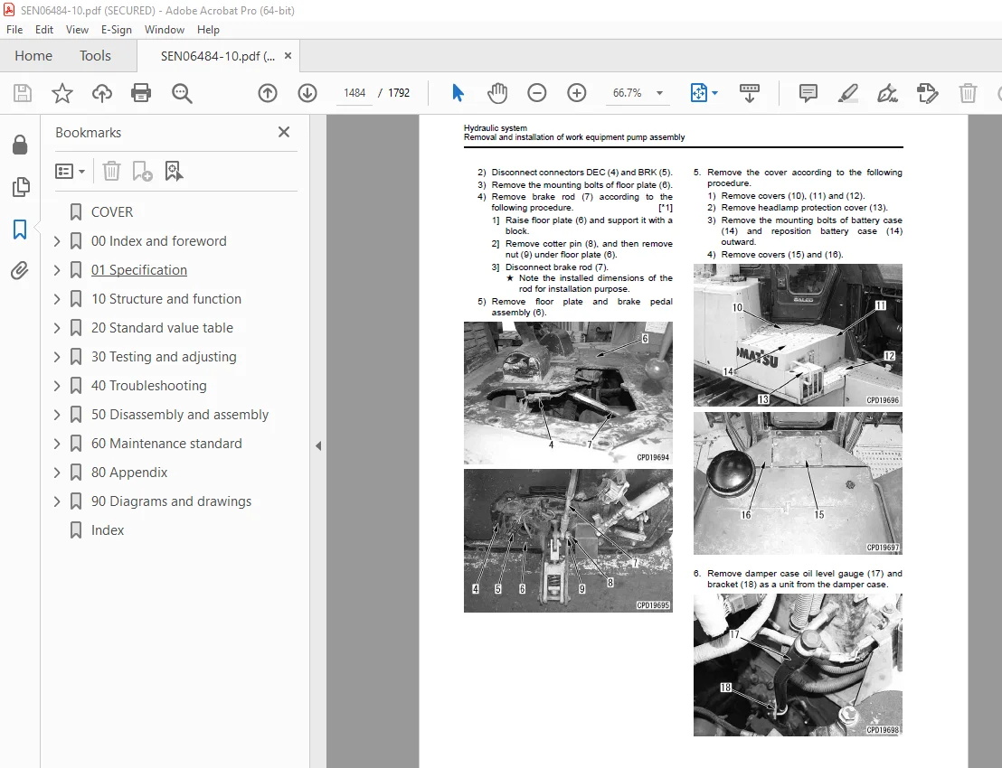
Removal and installation of work equipment pump assembly 1483
Removal and installation of fan pump assembly 1487
Removal and installation of control valve assembly 1488
Disassembly and assembly of control valve assembly 1490
Disassembly and assembly of blade PPC valve assembly 1495
Disassembly and assembly of ripper PPC valve assembly 1498
Disassembly and assembly of hydraulic cylinder assembly 1500
Disassembly and assembly of ripper pin puller cylinder assembly 1508
Work equipment 1511
Removal and installation of blade assembly 1511
Removal and installation of blade lift cylinder assembly 1513
Disassembly and assembly of blade assembly 1523
Disassembly and assembly of giant ripper assembly 1527
Cab and its attachments 1530
Removal and installation of ROPS guard 1530
Removal and installation of operator’ cab assembly 1531
Removal and installation of floor frame assembly 1535
Removal and installation of air conditioner unit assembly 1540
Removal and installation of operator’s seat isolator 1546
Disassembly and assembly of operator’s seat isolator 1547
Electrical system 1549
Removal and installation of transmission controller assembly and steering controller assembly 1549
Removal and installation of engine controller assembly 1550
Removal and installation of VHMS controller assembly 1552
Removal and installation of machine monitor assembly 1553
60 Maintenance standard 1555
Table of contents 1556
Engine and cooling system 1557
Engine mount 1557
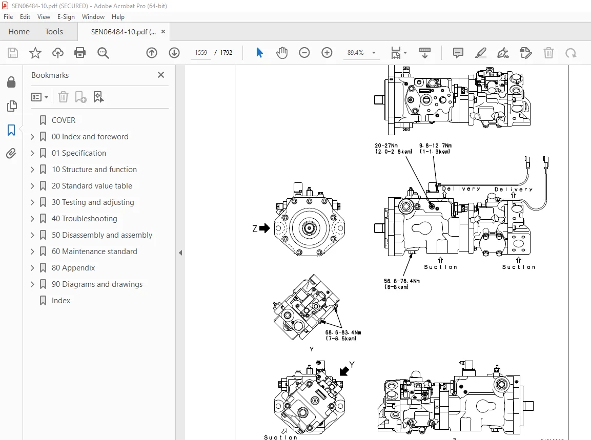
Cooling fan pump 1559
Cooling fan motor 1566
Power train 1568
Power train unit 1568
Damper and universal joint 1570
Torque converter and PTO 1573
Main relief valve and torque converter relief valve 1576
Lockup clutch ECMV and stator clutch ECMV 1577
Scavenging pump 1578
Transmission control 1579
Transmission 1580
Transmission lubricating oil relief valve 1584
Power train and lubrication pump 1585
Transfer, bevel gear shaft and steering unit 1586
Steering control valve 1592
Steering clutch ECMV and steering brake ECMV 1593
Parking brake valve 1594
Final drive 1595
Sprocket 1598
Undercarriage and frame 1600
Track frame 1600
Idler cushion 1602
Idler 1604
Track roller 1606
Carrier roller 1608
Track roller bogie 1609
Track shoe 1610
Main frame 1614
Suspension 1616
Hydraulic system 1621
PPC valve 1621
Hydraulic cylinder 1626
Quick drop valve 1629
Work equipment pump 1630
Control valve 1633
Self-pressure reducing valve 1645
Work equipment 1647
Cylinder stay 1647
Blade 1648
Cutting edge and end bit 1652
Ripper 1654
80 Appendix 1655
Contents 1656
CAB Heater 1657
Heater component 1657
Heater unit 1662
Blower unit 1664
FRESH/RECIRC air changeover damper 1665
Heater control panel 1666
Procedure for testing and troubleshooting 1668
Circuit diagram and arrangement of connector pins 1669
System diagram 1671
Parts and connectors layout (CAB heater) 1673
Testing temperature control 1677
Testing FRESH/RECIRC air changeover 1677
Testing relay 1678
Troubleshooting chart 1 1680
Troubleshooting chart 2 1681
Information in troubleshooting table 1682
Troubleshooting for power supply system (CAB heater does not operate) 1684
Troubleshooting for blower motor system (Air does not come out or air flow is abnormal) 1686
Troubleshooting for temperature control 1692
Troubleshooting for FRESH/RECIRC air changeover 1694
Additional heater does not operate 1696
Combustion-type heater 1700
Handling of on-board combustion preheater 1700
Overall layout of preheating device and flow of engine coolant duringpreheating 1701
Structure and function of combustion-type heater 1703
Electrical circuit diagram 1705
Operation and function 1706
Overheat prevention function 1707
Troubleshooting and repair instructions 1708
Introduction 1708
Troubleshooting of combustion-type heater 1709
Repair instructions of combustion-type heater 1715
Replace of combustion-type heater water pump 1734
Electrical circuit diagram of combustion-type heater 1739
90 Diagrams and drawings 1741
Contents 1742
Hydraulic diagrams and drawings 1743
Symbols used in hydraulic circuit diagrams 1743
Power train hydraulic diagrams and drawings 1745
Hydraulic circuit diagram 1747
Electrical diagrams and drawings 1751
Symbols used in electrical circuit diagrams 1751
Electrical circuit diagram 1755
Index 1783
DESCRIPTION:
Komatsu D375A-6 Bulldozer Shop Manual SEN06484-10 – PDF DOWNLOAD
SERIAL NUMBERS 60001 and up
How to read the shop manual
1. Composition of shop manual
This shop manual contains the necessary technical information for services performed in a workshop. For
ease of understanding, the manual is divided into the following sections.
00. Index and foreword
This section contains the index, foreword and safety and basic information.If any revision is made, the
LIST OF REVISED PAGES will be added.
01. Specification
This section explains the specifications of the machine.
10. Structure and function
This section explains the structure and function of each component.It serves not only to give an understanding
of the structure, but also serves as reference material for troubleshooting.
20. Standard value table
This section explains the standard values for new machine and judgement criteria for testing, adjusting,
and troubleshooting. This standard value table is used to check the standard values in testing and adjusting
and to judge parts in troubleshooting.
30. Testing and adjusting
This section explains measuring instruments and measuring methods for testing and adjusting, as well as
the adjusting method of each part.The standard values and judgment criteria for testing and adjusting are
explained in “Testing and adjusting”.
40. Troubleshooting
This section explains how to find out failed parts and how to repair them. The troubleshooting is divided
by failure modes. The “S mode” of the troubleshooting related to the engine may be also explained in the
Chassis volume and Engine volume. In this case, see the Chassis volume.
50. Disassembly and assembly
This section explains the special tools and procedures for removing, installing, disassembling, and assembling
each component, as well as precautions for them.In addition, tightening torque, and quantity and
weight of coating material, oil, grease, and coolant necessary for the work are also explained.
60. Maintenance standard
This section gives maintenance standard values of each component. The maintenance standard sub-section
explains the criteria and remedies for disassembly and service.
80. Appendix
This section explains the structure, function, testing, adjusting, and troubleshooting for the equipment not
classifiable in other sections.
90. Diagrams and drawings (chassis volume)/Repair and replacement of parts (engine volume)
q Chassis volume
This section gives hydraulic circuit diagrams and electrical circuit diagrams.
q Engine volume
This section explains the method of remanufacturing and repairing engine and replacing parts.
S.V 29/12/24


