Komatsu D375A-6R Crawler Bulldozer Shop Manual SEN05214-03 – PDF DOWNLOAD
Original price was: $49.95.$27.95Current price is: $27.95.
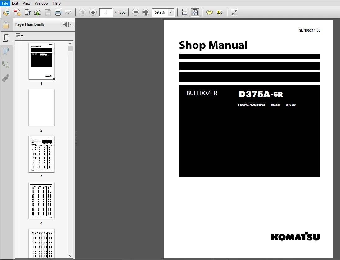
Komatsu D375A-6R Crawler Bulldozer Shop Manual
SERIAL NUMBERS 65001 and up
Description
Komatsu D375A-6R Crawler Bulldozer Shop Manual
FILE DETAILS:
Komatsu D375A-6R Crawler Bulldozer Shop Manual
Brands: Komatsu
Equipment Type: Crawler Bulldozer
Manuals Type: Shop Manual
Machine Model: D375A-6R
Serial Number: 65001 and up
Book Code: SEN05214-03
Language: English
Pages: 1766
File Format: Portable Document Format (PDF)
DESCRIPTION:
Komatsu D375A-6R Crawler Bulldozer Shop Manual
How to read the shop manual:
1. Composition of shop manual
This shop manual contains the necessary technical information for services performed in a workshop. For ease of understanding, the manual is divided into the following sections.
00. Index and foreword
This section contains the index, foreword, safety and basic information. If any revision is made, the LIST OF REVISED PAGES will be added.
01. Specification:
This section explains the specifications of the machine.
10. Structure and function:
This section explains the structure and function of each component. It serves not only to give an understanding for the structure of each component, but also serves as reference material for troubleshooting.
20. Standard value table:
This section explains the standard values for new machine and judgement criteria for testing, adjusting, and troubleshooting. This standard value table is used to check the standard values in testing and adjusting and to judge parts in troubleshooting.
30. Testing and adjusting:
This section explains measuring tools and measuring methods for testing and adjusting, as well as the adjusting method of each part. The standard values and judgment criteria for “Testing and adjusting” are
explained in “Standard value table”.
40. Troubleshooting:
This section explains how to find out failed parts and how to repair them. The troubleshooting is dividedby failure modes. The “S mode” of the troubleshooting related to the engine may be also explained in the
Chassis volume and Engine volume. In this case, see the Chassis volume.
50. Disassembly and assembly:
This section explains the special tools and procedures for removing, installing, disassembling, and assembling each component, as well as precautions for them. In addition, tightening torque, and quantity and
weight of coating material, oil, grease, and coolant necessary for the work are also explained.
60. Maintenance standard:
This section gives maintenance standard values of each component. The maintenance standard sub-section explains the criteria and remedies for disassembly and service.
80. Appendix:
This section explains the structure, function, testing, adjusting, and troubleshooting for the equipment not classifiable in other sections.
90. Diagrams and drawings (chassis volume) /Repair and replacement of parts (engine volume):
- Chassis volume
This section gives hydraulic circuit diagrams and electrical circuit diagrams. - Engine volume
This section explains the method of remanufacturing and repairing engine and replacing parts.
TABLE OF CONTENTS:
Komatsu D375A-6R Crawler Bulldozer Shop Manual
COVER
................................................................................................................................................................................................   1
Notice of revision....................................................................................................................................................................................   3
00 Index and foreword.................................................................................................................................................................................  12
	Table of contents.................................................................................................................................................................................  13
		Table of contents.............................................................................................................................................................................  13
	Forword and general information...................................................................................................................................................................  26
		Safety notice.................................................................................................................................................................................  27
		How to read the shop manual...................................................................................................................................................................  31
		Explanation of terms for maintenance standard.................................................................................................................................................  33
		Handling of electric equipment and hydraulic components.......................................................................................................................................  35
		Handling of connectors newly used for engines.................................................................................................................................................  44
		How to read electric wire code................................................................................................................................................................  47
		Precautions when carrying out work............................................................................................................................................................  50
		Method of disassembling and connecting push-pull type coupler.................................................................................................................................  53
		Standard tightening torque table..............................................................................................................................................................  56
		List of Abbreviation..........................................................................................................................................................................  60
		Conversion table..............................................................................................................................................................................  64
01 Specification......................................................................................................................................................................................  70
	Specification and technical data..................................................................................................................................................................  72
		Specification drawing.........................................................................................................................................................................  72
		Specifications................................................................................................................................................................................  73
		Weight table..................................................................................................................................................................................  78
		Table of fuel, coolant and lubricants.........................................................................................................................................................  80
10 Structure and function.............................................................................................................................................................................  82
	Engine and cooling system.........................................................................................................................................................................  85
		Cooling system................................................................................................................................................................................  85
		Cooling fan pump..............................................................................................................................................................................  88
		Cooling fan motor............................................................................................................................................................................. 109
	Power train....................................................................................................................................................................................... 115
		Power train................................................................................................................................................................................... 115
		Overall drawing of power train unit........................................................................................................................................................... 117
		Power train hydraulic equipment arrangement drawing........................................................................................................................................... 119
		Damper and universal joint.................................................................................................................................................................... 121
		Torque converter and PTO...................................................................................................................................................................... 123
		Torque converter control valve................................................................................................................................................................ 129
		Main relief valve and torque converter relief valve........................................................................................................................................... 131
		Lockup clutch ECMV and stator clutch ECMV..................................................................................................................................................... 133
		Scavenging pump............................................................................................................................................................................... 138
		Transmission control.......................................................................................................................................................................... 139
		PCCS lever.................................................................................................................................................................................... 141
		Transmission.................................................................................................................................................................................. 145
		Transmission ECMV............................................................................................................................................................................. 159
		Transmission lubrication relief valve......................................................................................................................................................... 164
		Steering and brake control.................................................................................................................................................................... 165
		Transfer unit, bevel gear shaft and steering.................................................................................................................................................. 167
		Steering control valve........................................................................................................................................................................ 173
		Steering clutch ECMV and Steering brake ECMV.................................................................................................................................................. 175
		Parking brake valve........................................................................................................................................................................... 183
		Sudden stop prevention valve.................................................................................................................................................................. 184
		Final drive................................................................................................................................................................................... 186
	Undercarriage and frame........................................................................................................................................................................... 191
		Track frame................................................................................................................................................................................... 191
		Idler cushion................................................................................................................................................................................. 193
		Track roller bogie............................................................................................................................................................................ 194
		Main frame.................................................................................................................................................................................... 195
		Suspension.................................................................................................................................................................................... 197
	Hydraulic system.................................................................................................................................................................................. 200
		Work equipment hydraulic piping diagram....................................................................................................................................................... 200
		PPC control piping diagram.................................................................................................................................................................... 204
		Work equipment control........................................................................................................................................................................ 205
		Hydraulic tank................................................................................................................................................................................ 207
		Accumulator................................................................................................................................................................................... 209
		PPC lock valve................................................................................................................................................................................ 210
		PPC valve..................................................................................................................................................................................... 211
		Piston valve.................................................................................................................................................................................. 223
		Quick drop valve.............................................................................................................................................................................. 224
		Pin puller switch............................................................................................................................................................................. 226
		Pin puller solenoid valve..................................................................................................................................................................... 227
		Blade control lever (only for the machine with dual tilt specification)....................................................................................................................... 229
		Work equipment pump........................................................................................................................................................................... 231
		Control valve................................................................................................................................................................................. 243
		Self-pressure reducing valve.................................................................................................................................................................. 268
	Work equipment.................................................................................................................................................................................... 275
		Cylinder stay................................................................................................................................................................................. 275
	Cab............................................................................................................................................................................................... 276
		Cab mount..................................................................................................................................................................................... 276
		Cab........................................................................................................................................................................................... 277
	Electrical system................................................................................................................................................................................. 279
		Engine control................................................................................................................................................................................ 279
		Engine control system......................................................................................................................................................................... 280
		CRI engine control system..................................................................................................................................................................... 289
		Monitor system................................................................................................................................................................................ 291
		Machine monitor............................................................................................................................................................................... 293
		Lamp system................................................................................................................................................................................... 311
		Engine preheat (electrical intake air heater) control......................................................................................................................................... 312
		Palm command control system................................................................................................................................................................... 313
		Sensor........................................................................................................................................................................................ 316
		Vehicle health monitoring system (VHMS)....................................................................................................................................................... 322
		ORBCOMM system................................................................................................................................................................................ 328
20 Standard value table............................................................................................................................................................................... 332
	Standard service value table...................................................................................................................................................................... 334
		Standard value table for engine............................................................................................................................................................... 334
		Standard value table for machine.............................................................................................................................................................. 335
30 Testing and adjusting.............................................................................................................................................................................. 344
	Tools for testing, adjusting and troubleshooting.................................................................................................................................................. 347
		Diagnosis equipment list...................................................................................................................................................................... 347
	Engine and cooling system......................................................................................................................................................................... 349
		Testing engine speed.......................................................................................................................................................................... 349
		Testing intake air pressure (boost pressure).................................................................................................................................................. 352
		Testing exhaust temperature................................................................................................................................................................... 354
		Testing exhaust gas color..................................................................................................................................................................... 357
		Adjusting valve clearance..................................................................................................................................................................... 359
		Measuring compression pressure................................................................................................................................................................ 361
		Testing blow-by pressure...................................................................................................................................................................... 364
		Testing engine oil pressure................................................................................................................................................................... 366
		Handling of fuel system devices............................................................................................................................................................... 367
		Releasing residual pressure from fuel system.................................................................................................................................................. 368
		Testing fuel pressure......................................................................................................................................................................... 369
		Handling of reduced cylinder mode operation................................................................................................................................................... 370
		Handling of no injection cranking operation................................................................................................................................................... 371
		Testing leakage from pressure limiter and return rate from injector........................................................................................................................... 372
		Bleeding air from fuel circuit................................................................................................................................................................ 375
		Testing fuel circuit for leakage.............................................................................................................................................................. 377
		Replacing and adjusting alternator and air conditioner compressor belt30...................................................................................................................... 378
		Measuring fan speed........................................................................................................................................................................... 379
		Testing fan circuit oil pressure.............................................................................................................................................................. 380
		Bleeding air from fan pump.................................................................................................................................................................... 381
		Adjusting fuel control dial and decelerator pedal............................................................................................................................................. 382
	Power train....................................................................................................................................................................................... 385
		Testing power train oil pressure.............................................................................................................................................................. 385
		Adjusting transmission output speed sensor.................................................................................................................................................... 399
		Simple test procedure for brake performance................................................................................................................................................... 400
		Adjusting brake pedal and parking brake lever................................................................................................................................................. 401
		Adjusting position of pccs lever console...................................................................................................................................................... 404
		Emergency escape method when there is failure in power train.................................................................................................................................. 405
	Undercarriage and frame........................................................................................................................................................................... 407
		Inspecting wear of sprocket................................................................................................................................................................... 407
		Testing and adjusting track shoe tension...................................................................................................................................................... 408
	Hydraulic system.................................................................................................................................................................................. 409
		Testing and adjusting work equipment oil pressure............................................................................................................................................. 409
		Testing control circuit main pressure......................................................................................................................................................... 412
		Testing PPC valve output pressure............................................................................................................................................................. 413
		Adjusting play of PPC valve................................................................................................................................................................... 415
		Testing output pressure of ripper pin-puller solenoid valve................................................................................................................................... 416
		Checking location of cause of hydraulic drift of blade and ripper............................................................................................................................. 417
		Testing leakage inside work equipment cylinder................................................................................................................................................ 418
		Releasing remaining pressure in work equipment cylinders...................................................................................................................................... 419
		Bleeding air from work equipment cylinders.................................................................................................................................................... 420
		Adjusting ripper lever position............................................................................................................................................................... 421
	Work equipment.................................................................................................................................................................................... 423
		Adjusting work equipment lock lever........................................................................................................................................................... 423
		Adjusting blade............................................................................................................................................................................... 424
	Cab and its attachments........................................................................................................................................................................... 427
		Testing and adjusting operator's cab.......................................................................................................................................................... 427
	Electrical system................................................................................................................................................................................. 433
		Special functions of machine monitor (EMMS)................................................................................................................................................... 433
		Handling of voltage circuit of engine controller.............................................................................................................................................. 491
		Adjustment method when controller has been replaced........................................................................................................................................... 492
		Preparation work for troubleshooting for electrical equipment system.......................................................................................................................... 496
		Inspection procedure of diode................................................................................................................................................................. 500
		Handling of optional devices.................................................................................................................................................................. 501
		Request for opening ORBCOMM terminal.......................................................................................................................................................... 502
		Initialization procedures for VHMS controller................................................................................................................................................. 504
		Using method of KOMTRAX functions of ORBCOMM terminal......................................................................................................................................... 518
		Precautions for replacing VHMS controller..................................................................................................................................................... 521
	Pm Clinic......................................................................................................................................................................................... 527
		Pm Clinic service............................................................................................................................................................................. 527
40 Troubleshooting.................................................................................................................................................................................... 538
	General information on troubleshooting............................................................................................................................................................ 547
		Points to remember when troubleshooting....................................................................................................................................................... 547
		Sequence of events in troubleshooting......................................................................................................................................................... 548
		Checks before troubleshooting................................................................................................................................................................. 549
		Classification and procedures for troubleshooting............................................................................................................................................. 574
		Failure codes table........................................................................................................................................................................... 577
		Classification and procedures for troubleshooting numbers..................................................................................................................................... 587
		Information in troubleshooting table.......................................................................................................................................................... 589
		Troubleshooting method for disconnecting wiring harness of pressure sensor system............................................................................................................. 591
		Connection table for connector pin numbers.................................................................................................................................................... 594
		T-branch box and T-branch adapter table....................................................................................................................................................... 630
		Connector list and layout..................................................................................................................................................................... 633
		Fuse locations table.......................................................................................................................................................................... 647
	Troubleshooting by failurecode.................................................................................................................................................................... 651
		Failure code [1380MW] Lock up clutch: Slip.................................................................................................................................................... 651
		Failure code [1500L0] Transmission clutch: Abnormal........................................................................................................................................... 652
		Failure code [15E0MW] Transmission clutch: Slip............................................................................................................................................... 653
		Failure code [15SAL1] Forward clutch: Fill high............................................................................................................................................... 655
		Failure code [15SALH] Forward clutch: Fill Low................................................................................................................................................ 657
		Failure code [15SBL1] Reverse clutch: Fill high............................................................................................................................................... 659
		Failure code [15SBLH] Reverse clutch: Fill Low................................................................................................................................................ 661
		Failure code [15SEL1] Speed 1st clutch: Fill high............................................................................................................................................. 663
		Failure code [15SELH] Speed 1st clutch: Fill Low.............................................................................................................................................. 665
		Failure code [15SFL1] Speed 2nd clutch: Fill high............................................................................................................................................. 667
		Failure code [15SFLH] Speed 2nd clutch: Fill Low.............................................................................................................................................. 669
		Failure code [15SGL1] Speed 3rd clutch: Fill high............................................................................................................................................. 671
		Failure code [15SGLH] Speed 3rd clutch: Fill Low.............................................................................................................................................. 673
		Failure code [15SJL1] L/U: Fill high.......................................................................................................................................................... 675
		Failure code [15SJLH] L/U: Fill low........................................................................................................................................................... 677
		Failure code [1800MW] P/T clutch: Slip........................................................................................................................................................ 679
		Failure code [2201L1] Right clutch: Fill high................................................................................................................................................. 681
		Failure code [2201LH] Right clutch: Fill low.................................................................................................................................................. 683
		Failure code [2202L1] Left clutch: Fill high.................................................................................................................................................. 685
		Failure code [2202LH] Left clutch: Fill low................................................................................................................................................... 687
		Failure code [2300NR] Brake Themal Load Abnormality........................................................................................................................................... 689
		Failure code [2301L1] Right brake: Fill high.................................................................................................................................................. 691
		Failure code [2301LH] Right brake: Fill low................................................................................................................................................... 693
		Failure code [2301NR] Steering Brake RH Themal Load Abnormality............................................................................................................................... 695
		Failure code [2302L1] Left brake: Fill high................................................................................................................................................... 697
		Failure code [2302LH] Left brake: Fill low.................................................................................................................................................... 699
		Failure code [2302NR] Steering Brake LH Themal Load Abnormality............................................................................................................................... 701
		Failure code [7RFAKA] ECM ACC CUT RELAY: Disconnection........................................................................................................................................ 703
		Failure code [7RFAKB] ECM ACC CUT RELAY: Short circuit........................................................................................................................................ 705
		Failure code [AA10NX] Air Cleaner Clogging.................................................................................................................................................... 707
		Failure code [AB00MA] Battery Charge Abnormal................................................................................................................................................. 709
		Failure code [B@BAZG] Eng Oil Press Low....................................................................................................................................................... 710
		Failure code [B@BAZK] Eng Oil Level Low....................................................................................................................................................... 711
		Failure code [B@BCNS] Eng Water Overheat...................................................................................................................................................... 712
		Failure code [B@BCZK] Eng Water Level Low..................................................................................................................................................... 713
		Failure code [B@CENS] T/C Oil Overheat........................................................................................................................................................ 714
		Failure code [B@HANS] Hyd Oil Overheat........................................................................................................................................................ 715
		Failure code [B@HAZK] Hyd Oil Level Low....................................................................................................................................................... 716
		Failure code [CA111] ECM Critical Internal Failure............................................................................................................................................ 717
		Failure code [CA115] Eng Ne and Bkup Speed Sens Error......................................................................................................................................... 719
		Failure code [CA122] Chg Air Press Sensor High Error.......................................................................................................................................... 721
		Failure code [CA123] Chg Air Press Sensor Low Error........................................................................................................................................... 723
		Failure code [CA131] Throttle Sensor High Error............................................................................................................................................... 725
		Failure code [CA132] Throttle Sensor Low Error................................................................................................................................................ 727
		Failure code [CA135] Eng Oil Press Sensor High Error.......................................................................................................................................... 729
		Failure code [CA141] Eng Oil Press Sensor Low Error........................................................................................................................................... 731
		Failure code [CA144] Coolant Temp Sens High Error............................................................................................................................................. 733
		Failure code [CA145] Coolant Temp Sens Low Error.............................................................................................................................................. 735
		Failure code [CA153] Chg Air Temp Sensor High Error........................................................................................................................................... 737
		Failure code [CA154] Chg Air Temp Sensor Low Error............................................................................................................................................ 739
		Failure code [CA187] Sens Supply 2 Volt Low Error............................................................................................................................................. 741
		Failure code [CA212] Eng Oil Temp Sensor High Error........................................................................................................................................... 743
		Failure code [CA213] Eng Oil Temp Sensor Low Error............................................................................................................................................ 745
		Failure code [CA221] Ambient Press Sens High Error............................................................................................................................................ 747
		Failure code [CA222] Ambient Press Sens Low Error............................................................................................................................................. 749
		Failure code [CA227] Sens Supply 2 Volt High Error............................................................................................................................................ 751
		Failure code [CA234] Eng Overspeed............................................................................................................................................................ 752
		Failure code [CA238] Ne Speed Sens Supply Volt Error.......................................................................................................................................... 753
		Failure code [CA263] Fuel Temp Sensor High Error.............................................................................................................................................. 755
		Failure code [CA265] Fuel Temp Sensor Low Error............................................................................................................................................... 757
		Failure code [CA271] IMV/PCV1 Short Error..................................................................................................................................................... 759
		Failure code [CA272] IMV/PCV1 Open Error...................................................................................................................................................... 760
		Failure code [CA273] PCV2 Short Error......................................................................................................................................................... 761
		Failure code [CA274] PCV2 Open Error.......................................................................................................................................................... 762
		Failure code [CA322] Inj #1 (L#1) Open/Short Error............................................................................................................................................ 763
		Failure code [CA323] Inj #5 (L#5) Open/Short Error............................................................................................................................................ 765
		Failure code [CA324] Inj #3 (L#3) Open/Short Error............................................................................................................................................ 767
		Failure code [CA325] Inj #6 (L#6) Open/Short Error............................................................................................................................................ 769
		Failure code [CA331] Inj #2 (L#2) Open/Short Error............................................................................................................................................ 771
		Failure code [CA332] Inj #4 (L#4) Open/Short Error............................................................................................................................................ 773
		Failure code [CA342] Calibration Code Incompatibility......................................................................................................................................... 775
		Failure code [CA351] Injectors Drive Circuit Error............................................................................................................................................ 776
		Failure code [CA352] Sens Supply 1 Volt Low Error............................................................................................................................................. 777
		Failure code [CA386] Sens Supply 1 Volt High Error............................................................................................................................................ 779
		Failure code [CA441] Battery Voltage Low Error................................................................................................................................................ 780
		Failure code [CA442] Battery Voltage High Error............................................................................................................................................... 781
		Failure code [CA449] Rail Press Very High Error............................................................................................................................................... 782
		Failure code [CA451] Rail Press Sensor High Error............................................................................................................................................. 783
		Failure code [CA452] Rail Press Sensor Low Error.............................................................................................................................................. 785
		Failure code [CA553] Rail Press High Error.................................................................................................................................................... 787
		Failure code [CA554] Rail Press Sensor In Range Error......................................................................................................................................... 788
		Failure code [CA559] Rail Press Low Error..................................................................................................................................................... 789
		Failure code [CA689] Eng Ne Speed Sensor Error................................................................................................................................................ 793
		Failure code [CA731] Eng Bkup Speed Sens Phase Error.......................................................................................................................................... 795
		Failure code [CA757] All Continuous Data Lost Error........................................................................................................................................... 796
		Failure code [CA778] Eng Bkup Speed Sensor Error.............................................................................................................................................. 797
		Failure code [CA1633] KOMNET Datalink Timeout Error........................................................................................................................................... 799
		Failure code [CA2185] Throt Sens Sup Volt High Error.......................................................................................................................................... 800
		Failure code [CA2186] Throt Sens Sup Volt Low Error........................................................................................................................................... 801
		Failure code [CA2249] Rail Press Very Low Error............................................................................................................................................... 802
		Failure code [D110KB] Battery Relay: Drive Short Circuit...................................................................................................................................... 803
		Failure code [D130KA] Neutral relay: Disconnection............................................................................................................................................ 805
		Failure code [D130KB] Neutral relay: Short circuit............................................................................................................................................ 807
		Failure code [D161KA] Back-up alarm releay: Disconnection..................................................................................................................................... 809
		Failure code [D161KB] Back-up alarm releay: Short circuit..................................................................................................................................... 811
		Failure code [D182KZ] Preheater Relay Abnormality............................................................................................................................................. 813
		Failure code [D190KA] ACC signal relay: Disconnection......................................................................................................................................... 815
		Failure code [D190KB] ACC signal relay: Short circuit......................................................................................................................................... 817
		Failure code [D1EFKA] Pre lub. motor relay: Disconnection..................................................................................................................................... 819
		Failure code [D1EFKB] Pre lub. motor relay: Short circuit..................................................................................................................................... 821
		Failure code [DAFRKR] Monitor: Can communication lost (PT).................................................................................................................................... 823
		Failure code [dAFRKR] Monitor: CAN communication lost (WE).................................................................................................................................... 824
		Failure code [DAFRMC] CAN Discon (Monitor Detected)........................................................................................................................................... 825
		Failure code [DB2RKR] ENG cont.: Can communication lost (PT).................................................................................................................................. 831
		Failure code [dB2RKR] ENG controller: CAN communication lost (WE)............................................................................................................................. 835
		Failure code [DB90KT] WE controller: Abnormality in controller................................................................................................................................ 836
		Failure code [DB91KK] WE controller: Source voltage reduction................................................................................................................................. 837
		Failure code [DB92KK] WE controller: Output voltage reduction................................................................................................................................. 839
		Failure code [DB97KK] WE cont.: Sensor voltage 5 V (2) reduction.............................................................................................................................. 841
		Failure code [DB99KQ] WE controller: Type select signal....................................................................................................................................... 843
		Failure code [DB9RKR] WE controller: Can communication lost (PT).............................................................................................................................. 844
		Failure code [DBB0KK] VHMS controller:Source voltage reduction................................................................................................................................ 847
		Failure code [DBB0KQ] VHMS connector connection abnormality................................................................................................................................... 849
		Failure code [DBB3KK] VHMS controller: Source voltage reduction............................................................................................................................... 850
		Failure code [DBB5KP] VHMS: Output sensor1 voltage reduction.................................................................................................................................. 853
		Failure code [DBB6KP] VHMS:Output sensor2 voltage reduction................................................................................................................................... 855
		Failure code [DBB7KP] VHMS:Output sensor3 voltage reduction................................................................................................................................... 857
		Failure code [DBBQKR] PT cont.: Can communication lost (VHMS)................................................................................................................................. 859
		Failure code [DBE0KT] PT controller: Abnormality in controller................................................................................................................................ 860
		Failure code [DBE1KK] PT controller: Source voltage reduction................................................................................................................................. 861
		Failure code [DBE2KK] PT controller: Output voltage reduction................................................................................................................................. 863
		Failure code [DBE5KK] PT cont.: Sensor voltage 5 V (1) reduction.............................................................................................................................. 865
		Failure code [DBE6KK] PT cont.: Sensor voltage 24V reduction.................................................................................................................................. 867
		Failure code [DBE7KK] PT cont.: Sensor voltage 5 V reduction.................................................................................................................................. 869
		Failure code [DBE9KQ] PT controller: Type select signal....................................................................................................................................... 871
		Failure code [DBERKR] PT controller: Can communication lost (WE).............................................................................................................................. 872
		Failure code [DD12KA] Shift up Sw: Disconnection.............................................................................................................................................. 875
		Failure code [DD12KB] Shift up Sw: Short circuit.............................................................................................................................................. 877
		Failure code [DD13KA] Shift down Sw: Disconnection............................................................................................................................................ 879
		Failure code [DD13KB] Shift down Sw: Short circuit............................................................................................................................................ 881
		Failure code [DD14KA] Parking lever Sw: Dissconnection........................................................................................................................................ 883
		Failure code [DD14KB] Parking lever Sw: Short circuit......................................................................................................................................... 885
		Failure code [DDB9L4] Reverse SW Signal disagreement.......................................................................................................................................... 887
		Failure code [DDE2KA] Pre lub. oil press sw: Disconnection.................................................................................................................................... 889
		Failure code [DDK3L4] Forward SW Signal disagreement.......................................................................................................................................... 891
		Failure code [DDK5KA] Shift switch disconnection.............................................................................................................................................. 893
		Failure code [DDK5KB] Shift switch short circuit.............................................................................................................................................. 895
		Failure code [DDN2LD] Blade tilt RH pressure SW abnormality................................................................................................................................... 897
		Failure code [DDN3LD] Blade tilt LH pressure SW abnormality................................................................................................................................... 899
		Failure code [DDN7KA] WEQ Knob Sw (down): Disconnection....................................................................................................................................... 901
		Failure code [DDN7KB] WEQ Knob Sw (down): Short circuit....................................................................................................................................... 903
		Failure code [DDN9KA] WEQ Knob Sw (up): Disconnection......................................................................................................................................... 905
		Failure code [DDN9KB] WEQ Knob Sw (up): Short circuit......................................................................................................................................... 907
		Failure code [DDNALD] Blade lift up pressure SW abnormality................................................................................................................................... 909
		Failure code [DDNCLD] Ripper lift down pressure SW abnormality................................................................................................................................ 913
		Failure code [DDNDLD] Ripper tilt in pressure SW abnormality.................................................................................................................................. 915
		Failure code [DDNELD] Ripper tilt back pressure SW abnormality................................................................................................................................ 917
		Failure code [DDNFLD] Blade lift down pressure SW abnormality................................................................................................................................. 919
		Failure code [DDNLKA] Weq lock Sw: Disconnection.............................................................................................................................................. 921
		Failure code [DDNLKB] Weq lock Sw: Short circuit.............................................................................................................................................. 923
		Failure code [DDT5KA] Neutral switch disconnection............................................................................................................................................ 925
		Failure code [DDT5KB] Neutral switch short circuit............................................................................................................................................ 927
		Failure code [DDT5KQ] Lever SPEC selection signal disagreement................................................................................................................................ 929
		Failure code [DDTSL1] S/C: Fill high.......................................................................................................................................................... 931
		Failure code [DDTSLH] S/C: Fill low........................................................................................................................................................... 933
		Failure code [DGE5KX] Ambient temp sensor abnormality......................................................................................................................................... 935
		Failure code [DGS1KX] Hyd oil temp: signal abnormal........................................................................................................................................... 937
		Failure code [DGT1KA] T/C oil temp sensor: Abnormal........................................................................................................................................... 939
		Failure code [DGT1KX] T/C oil temp sensor: Abnormal........................................................................................................................................... 941
		Failure code [DGT5KA] F exhaust temp sensor disconnection..................................................................................................................................... 943
		Failure code [DGT5KB] F exhaust temp sensor short circuit..................................................................................................................................... 945
		Failure code [DGT6KA] R exhaust temp sensor disconnection..................................................................................................................................... 947
		Failure code [DGT6KB] R exhaust temp sensor short circuit..................................................................................................................................... 949
		Failure code [DH21KA] Weq pressure sensor: Disconnection...................................................................................................................................... 951
		Failure code [DH21KB] Weq pressure sensor: Short circuit...................................................................................................................................... 953
		Failure code [DHE5KB] ENG blow-by pressure sensor disconnection............................................................................................................................... 955
		Failure code [DHE5KY] ENG blow-by pressure sensor short circuit............................................................................................................................... 957
		Failure code [DHT3KX] T/M oil pressure sensor abnormality..................................................................................................................................... 959
		Failure code [DHT5KA] T/C in-pressure sensor: Disconnection................................................................................................................................... 961
		Failure code [DHT5KB] T/C in-pressure sensor: Short circuit................................................................................................................................... 963
		Failure code [DHT7KA] T/C out-pressure sensor: Disconnection.................................................................................................................................. 965
		Failure code [DHT7KB] T/C out-pressure sensor: Short circuit.................................................................................................................................. 967
		Failure code [DK10KA] Fuel control Dial: Disconnection........................................................................................................................................ 969
		Failure code [DK10KB] Fuel control Dial: Short circuit........................................................................................................................................ 971
		Failure code [DK30KA] ST lever 1: Disconnection............................................................................................................................................... 973
		Failure code [DK30KB] ST lever 1: Short circuit............................................................................................................................................... 975
		Failure code [DK30KX] ST lever: Out of normal range........................................................................................................................................... 977
		Failure code [DK30KZ] ST lever: Disconnection or short circuit................................................................................................................................ 978
		Failure code [DK30L8] ST lever: Signal mismatch............................................................................................................................................... 979
		Failure code [DK31KA] ST lever 2: Disconnection............................................................................................................................................... 981
		Failure code [DK31KB] ST lever 2: Short circuit............................................................................................................................................... 983
		Failure code [DK40KA] Brake potentiometer: Disconnection...................................................................................................................................... 985
		Failure code [DK40KB] Brake potentiometer: Short circuit...................................................................................................................................... 987
		Failure code [DK55KX] FR lever: Out of normal range........................................................................................................................................... 989
		Failure code [DK55KZ] FR lever: Disconnection or short circuit................................................................................................................................ 990
		Failure code [DK55L8] FR lever: Signal mismatch............................................................................................................................................... 991
		Failure code [DK56KA] FR lever 1: Disconnection............................................................................................................................................... 993
		Failure code [DK56KB] FR lever 1: Short circuit............................................................................................................................................... 995
		Failure code [DK57KA] FR lever 2: Disconnection............................................................................................................................................... 997
		Failure code [DK57KB] FR lever 2: Short circuit............................................................................................................................................... 999
		Failure code [DK60KA] Acceleration sensor: Disconnection......................................................................................................................................1001
		Failure code [DK60KB] Acceleration sensor: Short circuit......................................................................................................................................1003
		Failure code [DKH1KA] Pitch angle sensor: Disconnection.......................................................................................................................................1005
		Failure code [DKH1KB] Pitch angle sensor: Short circuit.......................................................................................................................................1007
		Failure code [DLF1KA] T/C out-speed sensor: Disconnection.....................................................................................................................................1009
		Failure code [DLM3KA] Fan rev. sensor: Disconnection..........................................................................................................................................1011
		Failure code [DLM3MB] Fan control: Decline....................................................................................................................................................1013
		Failure code [DLT3KA] T/M out-speed sensor: Disconnection.....................................................................................................................................1014
		Failure code [DLT3KB] T/M out-speed sensor: Abnormal..........................................................................................................................................1015
		Failure code [DW59KA] Blade dual selector SOL disconnection...................................................................................................................................1016
		Failure code [DW59KB] Blade dual selector SOL short circuit...................................................................................................................................1017
		Failure code [DW59KY] Blade dual selector SOL hot short.......................................................................................................................................1019
		Failure code [DW5AKA] Blade pitch selector SOL disconnection..................................................................................................................................1021
		Failure code [DW5AKB] Blade pitch selector SOL short circuit..................................................................................................................................1022
		Failure code [DW5AKY] Blade pitch selector SOL Short circuit..................................................................................................................................1023
		Failure code [DW7BKA] Fan rev EPC: Disconnection..............................................................................................................................................1025
		Failure code [DW7BKB] Fan rev EPC: Short circuit..............................................................................................................................................1026
		Failure code [DWN3KA] Ssp solenoid: Disconnection.............................................................................................................................................1027
		Failure code [DWN3KB] Ssp solenoid: Short circuit.............................................................................................................................................1029
		Failure code [DWN3KY] SSP solenoid: Short circuit.............................................................................................................................................1031
		Failure code [DWN5KA] Fan pump solenoid 1: Disconnection......................................................................................................................................1033
		Failure code [DWN5KB] Fan pump solenoid 1: Short circuit......................................................................................................................................1035
		Failure code [DWN5KY] Fan pump solenoid 1: Short circuit......................................................................................................................................1037
		Failure code [DWNCKA] Fan pump solenoid 2: Disconnection......................................................................................................................................1039
		Failure code [DWNCKB] Fan pump solenoid 2: Short circuit......................................................................................................................................1041
		Failure code [DWNCKY] Fan pump solenoid 2: Short circuit......................................................................................................................................1043
		Failure code [DXH1KA] Lock-up ECMV: Disconnection.............................................................................................................................................1045
		Failure code [DXH1KB] Lock-up ECMV: Short circuit.............................................................................................................................................1046
		Failure code [DXH1KY] Lock-up ECMV: Short circuit.............................................................................................................................................1047
		Failure code [DXH4KA] 1st clutch ECMV: Disconnection..........................................................................................................................................1049
		Failure code [DXH4KB] 1st clutch ECMV: Short circuit..........................................................................................................................................1051
		Failure code [DXH4KY] 1st clutch ECMV: Short circuit..........................................................................................................................................1053
		Failure code [DXH5KA] 2nd clutch ECMV: Disconnection..........................................................................................................................................1055
		Failure code [DXH5KB] 2nd clutch ECMV: Short circuit..........................................................................................................................................1057
		Failure code [DXH5KY] 2nd clutch ECMV: Short circuit..........................................................................................................................................1059
		Failure code [DXH6KA] 3rd clutch ECMV: Disconnection..........................................................................................................................................1061
		Failure code [DXH6KB] 3rd clutch ECMV: Short circuit..........................................................................................................................................1063
		Failure code [DXH6KY] 3rd clutch ECMV: Short circuit..........................................................................................................................................1065
		Failure code [DXH7KA] R clutch ECMV: Disconnection............................................................................................................................................1067
		Failure code [DXH7KB] R clutch ECMV: Short circuit............................................................................................................................................1069
		Failure code [DXH7KY] R clutch ECMV: Short circuit............................................................................................................................................1071
		Failure code [DXH8KA] F clutch ECMV: Disconnection............................................................................................................................................1073
		Failure code [DXH8KB] F clutch ECMV: Short circuit............................................................................................................................................1075
		Failure code [DXH8KY] F clutch ECMV: Short circuit............................................................................................................................................1077
		Failure code [DXH9KA] Right clutch ECMV: Disconnection........................................................................................................................................1079
		Failure code [DXH9KB] Right clutch ECMV: Short circuit........................................................................................................................................1081
		Failure code [DXH9KY] Right clutch ECMV: Short circuit........................................................................................................................................1083
		Failure code [DXHAKA] Left clutch ECMV: Disconnection.........................................................................................................................................1085
		Failure code [DXHAKB] Left clutch ECMV: Short circuit.........................................................................................................................................1087
		Failure code [DXHAKY] Left clutch ECMV: Short circuit.........................................................................................................................................1089
		Failure code [DXHBKA] Right brake ECMV: Disconnection.........................................................................................................................................1091
		Failure code [DXHBKB] Right brake ECMV: Short circuit.........................................................................................................................................1093
		Failure code [DXHBKY] Right brake ECMV: Short circuit.........................................................................................................................................1095
		Failure code [DXHCKA] Left brake ECMV: Disconnection..........................................................................................................................................1097
		Failure code [DXHCKB] Left brake ECMV: Short circuit..........................................................................................................................................1099
		Failure code [DXHCKY] Left brake ECMV: Short circuit..........................................................................................................................................1101
		Failure code [DXJBKA] S/C ECMV: Disconnection.................................................................................................................................................1103
		Failure code [DXJBKB] S/C ECMV: Short circuit.................................................................................................................................................1104
		Failure code [DXJBKY] S/C ECMV: Short circuit.................................................................................................................................................1105
		Failure code [DY2HKA] Pre lub. motor: Disconnection...........................................................................................................................................1107
		Failure code [F@BBZL] ENG blow-by pressure high level.........................................................................................................................................1109
		Failure code [F@BYNR] F exhaust temp high level (2)...........................................................................................................................................1110
		Failure code [F@BYNS] F exhaust temp high level (1)...........................................................................................................................................1111
		Failure code [F@BZNR] R exhaust temp high level (2)...........................................................................................................................................1112
		Failure code [F@BZNS] R exhaust temp high level (1)...........................................................................................................................................1113
	Troubleshooting of electrical system (E-mode).....................................................................................................................................................1115
		Information contained in troubleshooting table................................................................................................................................................1115
		E-1 Engine does not start (starting motor does not turn)......................................................................................................................................1117
		E-2 Preheater does not operate................................................................................................................................................................1121
		E-3 When starting switch is turned ON, machine monitor displays nothing.......................................................................................................................1125
		E-4 When starting switch is turned ON (before starting engine), basic check item lights up....................................................................................................1129
		E-5 Precaution item lights up while engine is running.........................................................................................................................................1131
		E-6 Emergency stop item lights up while engine is running.....................................................................................................................................1133
		E-7 Engine coolant temperature gauge does not indicate normally...............................................................................................................................1134
		E-8 Fuel gauge does not indicate properly.....................................................................................................................................................1135
		E-9 Power train oil temperature gauge (multi-gauge) does not indicate normally................................................................................................................1137
		E-10 Hydraulic temperature gauge (multi-gauge) does not indicate normally.....................................................................................................................1138
		E-11 Contents of display by machine monitor are different from applicable machine.............................................................................................................1139
		E-12 Machine monitor does not display some items..............................................................................................................................................1139
		E-13 Function switch does not work............................................................................................................................................................1139
		E-14 Operation mode does not change...........................................................................................................................................................1140
		E-15 Gearshift mode does not change...........................................................................................................................................................1140
		E-16 Customize function does not operate normally.............................................................................................................................................1141
		E-17 Customize memory function does not operate normally......................................................................................................................................1141
		E-18 Alarm buzzer does not sound or does not stop.............................................................................................................................................1142
		E-19 When starting switch is turned OFF, service meter is not displayed40.....................................................................................................................1142
		E-20 Machine monitor cannot be set in service mode............................................................................................................................................1142
		E-21 The ripper pin puller cylinder does not operate..........................................................................................................................................1143
		E-22 Horn does not sound or does not stop.....................................................................................................................................................1145
		E-23 Back-up alarm does not sound or does not stop............................................................................................................................................1147
		E-24 Fan does not reverse.....................................................................................................................................................................1149
		E-25 The head lamp and rear lamp do not light up..............................................................................................................................................1150
		E-26 Windshield wiper does not operate........................................................................................................................................................1159
		E-27 Window washer does not operate...........................................................................................................................................................1167
		E-28 Electric priming pump does not operate or does not stop automati cally...................................................................................................................1175
		E-29 Orbcomm terminal does not operate normally (Data are not transmitted)....................................................................................................................1177
		E-30 Gear cannot be shifted...................................................................................................................................................................1179
	Troubleshooting of hydraulic and mechanical system (H-mode).......................................................................................................................................1181
		Information in troubleshooting table..........................................................................................................................................................1181
		List of Failure Modes and Causes..............................................................................................................................................................1183
		H-1 Machine lacks power(or drawbar pull)......................................................................................................................................................1185
		H-2 Machine cannot travel (at 2nd or 3rd each speed)..........................................................................................................................................1187
		H-3 Machine cannot travel at any gear speeds..................................................................................................................................................1188
		H-4 Machine travels only in one direction, forward or reverse.................................................................................................................................1190
		H-5 Large time lag at gear shifting or directional change.....................................................................................................................................1191
		H-6 Machine connot turn.......................................................................................................................................................................1192
		H-7 Machine turns only to one side............................................................................................................................................................1193
		H-8 Machine overruns at turnning..............................................................................................................................................................1194
		H-9 Brake does not work.......................................................................................................................................................................1195
		H-10 Torque converter does not lock up........................................................................................................................................................1196
		H-11 Power train oil overheats................................................................................................................................................................1197
		H-12 All work equipment operates too slow or lacks power......................................................................................................................................1198
		H-13 All work equipment does not operate......................................................................................................................................................1199
		H-14 Blade lift cylinder speed is too slow or lacks power.....................................................................................................................................1200
		H-15 Blade tilt cylinder speed is too slow or lacks power.....................................................................................................................................1201
		H-16 Ripper lift cylinder speed is too slow or lacks power....................................................................................................................................1202
		H-17 Ripper tilt cylinder speed is too slow or lacks power....................................................................................................................................1203
		H-18 Excessive hydraulic drift of blade lift cylinder.........................................................................................................................................1204
		H-19 Excessive hydraulic drift of blade tilt cylinder.........................................................................................................................................1205
		H-20 Excessive hydraulic drift of ripper lift cylinder........................................................................................................................................1206
		H-21 Ripper pin puller cylinder does not operate (machine with giant ripper)..................................................................................................................1207
		H-22 Blade pitch does not work (machine with dual tilt specification).........................................................................................................................1208
		H-23 Abnormal noise from around work equipment pump...........................................................................................................................................1209
		H-24 Abnormal fan rotation(noise and/or vibration are abnormally large or engine overheats)...................................................................................................1210
	Troubleshooting of engine (S-mode)................................................................................................................................................................1211
		Method of using troubleshooting chart.........................................................................................................................................................1211
		S-1 Engine does not start easily..............................................................................................................................................................1215
		S-2 Engine does not start.....................................................................................................................................................................1216
		S-3 Engine does not rev up smoothly (response-up is poor).....................................................................................................................................1219
		S-4 Engine stops during operation.............................................................................................................................................................1220
		S-5 Engine does not rotate smoothly (hunting).................................................................................................................................................1221
		S-6 Engine lacks power (or output shortage)...................................................................................................................................................1222
		S-7 Exhaust smoke is black (Incomplete combustion)............................................................................................................................................1223
		S-8 Oil is consumption is excessive(or exhaust smoke is blue).................................................................................................................................1224
		S-9 Engine oil becomes contaminated quickly...................................................................................................................................................1225
		S-10 Fuel consumption is excessive............................................................................................................................................................1226
		S-11 Oil mixes into coolant(coolant blows back or is reduced).................................................................................................................................1227
		S-12 Engine pressure monitor lights up (drop in engine oil pressure)..........................................................................................................................1228
		S-13 Oil level rises (Coolant or fuel mixes into oil).........................................................................................................................................1229
		S-14 Coolant temperature rises too high (overheating).........................................................................................................................................1230
		S-15 Abnormal noise is heard..................................................................................................................................................................1231
		S-16 Vibration is excessive...................................................................................................................................................................1232
		S-17 Air cannot be bled from fuel circuit (when air bleeding is performed after filter is replaced or fuel is used up and then air is bled, engine does not start or it starts but stalls)....1233
50 Disassembly and assembly...........................................................................................................................................................................1236
	General information on disassembly and assembly...................................................................................................................................................1239
		How to read this manual.......................................................................................................................................................................1239
		Coating materials list........................................................................................................................................................................1241
		Special tool list.............................................................................................................................................................................1244
		Sketches of special tools.....................................................................................................................................................................1252
	Engine and cooling system.........................................................................................................................................................................1260
		Removal and installation of fuel supply pump assembly.........................................................................................................................................1260
		Removal and installation of fuel injector assembly............................................................................................................................................1265
		Removal and installation of cylinder head assembly............................................................................................................................................1270
		Removal and installation of radiator guard assembly...........................................................................................................................................1285
		Removal and installation of cooling assembly (radiator, after cooler, and hydraulic oil cooler)...............................................................................................1290
		Removal and installation of radiator..........................................................................................................................................................1295
		Removal and installation of hydraulic oil cooler..............................................................................................................................................1297
		Removal and installation of aftercooler.......................................................................................................................................................1298
		Removal and installation of engine assembly...................................................................................................................................................1299
		Removal and installation of engine hood assembly..............................................................................................................................................1306
		Removal and installation of engine front seal.................................................................................................................................................1309
		Removal and installation of engine rear seal..................................................................................................................................................1311
		Removal and installation of fan drive assembly................................................................................................................................................1315
		Removal and installation of fan motor assembly................................................................................................................................................1317
		Removal and installation of fuel tank assembly................................................................................................................................................1319
	Power train.......................................................................................................................................................................................1321
		Removal and installation of damper assembly...................................................................................................................................................1321
		Disassembly and assembly of damper assembly...................................................................................................................................................1325
		Removal and installation of power train unit assembly.........................................................................................................................................1328
		Disconnection and connection of power train unit assembly.....................................................................................................................................1334
		Disassembly and assembly of PTO assembly......................................................................................................................................................1343
		Disassembly and assembly of torque converter assembly.........................................................................................................................................1349
		Disassembly and assembly of TORQFLOW transmission assembly....................................................................................................................................1358
		Disassembly and assembly of steering case assembly............................................................................................................................................1385
		Removal and installation of power train pump and lubrication pump assembly....................................................................................................................1401
		Removal and installation of scavenging pump assembly..........................................................................................................................................1402
		Removal and installation of final drive assembly..............................................................................................................................................1403
		Disassembly and assembly of final drive assembly..............................................................................................................................................1405
	Undercarriage and frame...........................................................................................................................................................................1418
		Removal and installation of track frame assembly..............................................................................................................................................1418
		Removal and installation of idler assembly....................................................................................................................................................1423
		Disassembly and assembly of idler assembly....................................................................................................................................................1424
		Removal and installation of recoil spring assembly............................................................................................................................................1428
		Disassembly and assembly of recoil spring assembly............................................................................................................................................1433
		Removal and installation of track roller assembly.............................................................................................................................................1435
		Disassembly and assembly of track roller assembly.............................................................................................................................................1438
		Removal and installation of carrier roller assembly...........................................................................................................................................1441
		Disassembly and assembly of carrier roller assembly...........................................................................................................................................1442
		Removal and installation of bogie assembly....................................................................................................................................................1446
		Disassembly and assembly of bogie assembly....................................................................................................................................................1451
		Removal and installation of first bogie assembly..............................................................................................................................................1453
		Separation and connection of track shoe assembly..............................................................................................................................................1458
		Overall disassembly and assembly of track shoe................................................................................................................................................1462
		Link press press-fitting jig dimensions.......................................................................................................................................................1479
		Disassembly and assembly of one link assembly in the field....................................................................................................................................1480
		Disassembly and assembly of master link.......................................................................................................................................................1485
		Removal and installation of pivot shaft assembly..............................................................................................................................................1489
		Removal and installation of equalizer bar.....................................................................................................................................................1490
		Disassembly and assembly of equalizer bar bushing.............................................................................................................................................1494
		Removal and installation of segment tooth.....................................................................................................................................................1496
	Hydraulic system..................................................................................................................................................................................1497
		Removal and installation of hydraulic tank assembly...........................................................................................................................................1497
		Removal and installation of work equipment pump assembly......................................................................................................................................1500
		Removal and installation of fan pump assembly.................................................................................................................................................1504
		Removal and installation of control valve assembly............................................................................................................................................1506
		Disassembly and assembly of control valve assembly............................................................................................................................................1508
		Disassembly and assembly of blade PPC valve assembly..........................................................................................................................................1513
		Disassembly and assembly of ripper PPC valve assembly.........................................................................................................................................1516
		Disassembly and assembly of hydraulic cylinder assembly.......................................................................................................................................1518
		Disassembly and assembly of ripper pin puller cylinder assembly...............................................................................................................................1526
	Work equipment....................................................................................................................................................................................1529
		Removal and installation of blade assembly....................................................................................................................................................1529
		Disassembly and assembly of blade assembly....................................................................................................................................................1531
		Disassembly and assembly of giant ripper assembly.............................................................................................................................................1535
	Cab and its attachments...........................................................................................................................................................................1538
		Removal and installation of ROPS guard........................................................................................................................................................1538
		Removal and installation of operator's cab assembly...........................................................................................................................................1539
		Removal and installation of floor frame assembly..............................................................................................................................................1543
		Removal and installation of air conditioner unit assembly.....................................................................................................................................1548
	Electrical system.................................................................................................................................................................................1554
		Removal and installation of transmission controller assembly and steering controller assembly.................................................................................................1554
		Removal and installation of engine controller assembly........................................................................................................................................1555
		Removal and installation of VHMS controller assembly..........................................................................................................................................1557
		Removal and installation of machine monitor assembly..........................................................................................................................................1558
60 Maintenance standard...............................................................................................................................................................................1560
	Engine and cooling system.........................................................................................................................................................................1562
		Engine mount..................................................................................................................................................................................1562
		Cooling fan pump..............................................................................................................................................................................1564
		Cooling fan motor.............................................................................................................................................................................1571
	Power train.......................................................................................................................................................................................1573
		Power train unit..............................................................................................................................................................................1573
		Damper and universal joint....................................................................................................................................................................1575
		Torque converter and PTO......................................................................................................................................................................1578
		Main relief valve and torque converter relief valve...........................................................................................................................................1581
		Lockup clutch ECMV and stator clutch ECMV.....................................................................................................................................................1582
		Scavenging pump...............................................................................................................................................................................1583
		Transmission control..........................................................................................................................................................................1584
		Transmission..................................................................................................................................................................................1585
		Transmission lubricating oil relief valve.....................................................................................................................................................1590
		Power train and lubrication pump..............................................................................................................................................................1591
		Transfer, bevel gear shaft and steering unit..................................................................................................................................................1593
		Steering control valve........................................................................................................................................................................1599
		Steering clutch ECMV and steering brake ECMV..................................................................................................................................................1600
		Parking brake valve...........................................................................................................................................................................1601
		Final drive...................................................................................................................................................................................1602
		Sprocket......................................................................................................................................................................................1605
	Undercarriage and frame...........................................................................................................................................................................1607
		Track frame...................................................................................................................................................................................1607
		Idler cushion.................................................................................................................................................................................1609
		Idler.........................................................................................................................................................................................1611
		Track roller..................................................................................................................................................................................1613
		Carrier roller................................................................................................................................................................................1615
		Track roller bogie............................................................................................................................................................................1616
		Track shoe....................................................................................................................................................................................1617
		Main frame....................................................................................................................................................................................1621
		Suspension....................................................................................................................................................................................1623
	Hydraulic system..................................................................................................................................................................................1627
		PPC valve.....................................................................................................................................................................................1627
		Hydraulic cylinder............................................................................................................................................................................1633
		Quick drop valve..............................................................................................................................................................................1636
		Work equipment pump...........................................................................................................................................................................1637
		Control valve.................................................................................................................................................................................1640
		Self-pressure reducing valve..................................................................................................................................................................1653
	Work equipment....................................................................................................................................................................................1656
		Cylinder stay.................................................................................................................................................................................1656
		Blade.........................................................................................................................................................................................1657
		Cutting edge and end bit......................................................................................................................................................................1661
		Ripper........................................................................................................................................................................................1663
80 Appendix...........................................................................................................................................................................................1666
	Air conditioner...................................................................................................................................................................................1668
		Precautions for refrigerant...................................................................................................................................................................1668
		Air conditioner component.....................................................................................................................................................................1669
		Configuration and function of refrigeration cycle.............................................................................................................................................1671
		Outline of refrigeration cycle................................................................................................................................................................1672
		Air conditioner unit..........................................................................................................................................................................1675
		Blower unit...................................................................................................................................................................................1679
		FRESH/RECIRC air changeover damper............................................................................................................................................................1680
		Compressor....................................................................................................................................................................................1681
		Condenser.....................................................................................................................................................................................1682
		Receiver drier................................................................................................................................................................................1683
		Air conditioner control panel.................................................................................................................................................................1685
		Procedure for testing and troubleshooting.....................................................................................................................................................1687
		Circuit diagram and arrangement of connector pins.............................................................................................................................................1689
		System diagram................................................................................................................................................................................1691
		Parts and connectors layout...................................................................................................................................................................1693
		Testing temperature control...................................................................................................................................................................1697
		Testing FRESH/RECIC air changeover............................................................................................................................................................1698
		Testing relay.................................................................................................................................................................................1699
		Troubleshooting chart 1.......................................................................................................................................................................1701
		Troubleshooting chart 2.......................................................................................................................................................................1703
		Information in troubleshooting table..........................................................................................................................................................1705
		Troubleshooting for power supply system (Air conditioner does not operate)....................................................................................................................1707
		Troubleshooting for compressor system (Air is not cooled).....................................................................................................................................1709
		Troubleshooting for blower motor system (Air does not come out or air flow is abnormal).......................................................................................................1713
		Troubleshooting for temperature control.......................................................................................................................................................1719
		Troubleshooting for FRESH/RECIRC air changeover...............................................................................................................................................1721
		Troubleshooting with gauge pressure...........................................................................................................................................................1723
		Connection of service tool....................................................................................................................................................................1725
		Precautions for disconnecting and connecting..................................................................................................................................................1727
		Handling of compressor oil....................................................................................................................................................................1729
90 Diagrams and drawings..............................................................................................................................................................................1732
	Hydraulic diagrams and drawings...................................................................................................................................................................1734
		Symbols used in hydraulic circuit diagrams....................................................................................................................................................1734
		Power train hydraulic circuit diagram.........................................................................................................................................................1736
		Hydraulic circuit diagram.....................................................................................................................................................................1737
	Electrical diagrams and drawings..................................................................................................................................................................1739
		Symbols used in electrical circuit diagrams...................................................................................................................................................1739
		Electrical circuit diagram....................................................................................................................................................................1743
Index.................................................................................................................................................................................................1757
KOMATSU D375A-6R CRAWLER BULLDOZER SHOP MANUAL SEN05214-03 – PDF DOWNLOAD:
IMAGES PREVIEW OF THE MANUAL:
PLEASE NOTE:
- This is not a physical manual but a digital manual – meaning no physical copy will be couriered to you. The manual can be yours in the next 2 mins as once you make the payment, you will be directed to the download page IMMEDIATELY.
- This is the same manual used by the dealers inorder to diagnose your vehicle of its faults.
- Require some other service manual or have any queries: please WRITE to us at [email protected]


