KOMATSU D51EXi-24E0 D51PXi-24E0 BULLDOZER SHOP MANUAL SEN06887-07 – PDF DOWNLOAD
$42.95
KOMATSU D51EXi-24E0 D51PXi-24E0 BULLDOZER SHOP MANUAL SEN06887-07 – PDF DOWNLOAD
Description
KOMATSU D51EXi-24E0 D51PXi-24E0 BULLDOZER SHOP MANUAL SEN06887-07 – PDF DOWNLOAD
FILE DETAILS:
KOMATSU D51EXi-24E0 D51PXi-24E0 BULLDOZER SHOP MANUAL SEN06887-07 – PDF DOWNLOAD
Language : English
Pages : 3264
Downloadable : Yes
File Type : PDF
IMAGES PREVIEW OF THE MANUAL:
![]()
![]()
![]()
TABLE OF CONTENTS:
KOMATSU D51EXi-24E0 D51PXi-24E0 BULLDOZER SHOP MANUAL SEN06887-07 – PDF DOWNLOAD
Index
00 Index and Foreword 00-1
Foreword, Safety, Basic Information 00-21
How to Read the Shop Manual 00-21
Safety Notice for Operation 00-23
Precautions to Prevent Fire 00-31
Procedures If Fire Occurs 00-33
Precautions for Disposing of Waste Materials 00-34
Procedures for Exhaust Gas Regulations 00-35
Precautions for DEF 00-36
Store DEF 00-37
Precautions When You Handle Hydraulic Equipment 00-38
Precautions When You Disconnect and Connect Pipings 00-41
Precautions When You Handle Electrical Equipment 00-48
Precautions When You Handle Fuel System Equipment 00-50
Precautions When You Handle Intake System Equipment 00-51
Practical Use of KOMTRAX 00-52
Disconnect and Connect Push-Pull Type Coupler 00-53
Precautions for Disconnection and Connection of Connectors 00-57
How to Disconnect and Connect Deutsch Connector 00-61
How to Disconnect and Connect Slide Lock Type Connector 00-62
How to Disconnect and Connect Connector with Lock to Pull 00-64
How to Disconnect and Connect Connector with Lock to Push 00-65
How to Disconnect and Connect Connector with Housing to Rotate 00-67
How to Read the Codes for Electric Cable 00-68
Explanation of Terms for Maintenance Standard 00-72
Standard Tightening Torque Table 00-75
Conversion Table 00-82
Abbreviation List 00-87
01 Specifications 01-1
Table of Contents 01-2
Specifications 01-3
Specification Drawing 01-3
Specifications 01-7
Weight Table 01-18
Fuel, Coolant, Lubricant 01-22
10 Structure and Function 10-1
Table of Contents 10-2
Urea SCR System 10-6
Layout Drawing of Urea SCR System 10-6
Urea SCR System Diagram (Divided Type) 10-8
Function of Urea SCR System 10-9
Component Parts of Urea SCR System 10-18
Boot-up System 10-27
Layout Drawing of Boot-up System 10-27
System Operating Lamp System 10-28
Battery Disconnect Switch 10-30
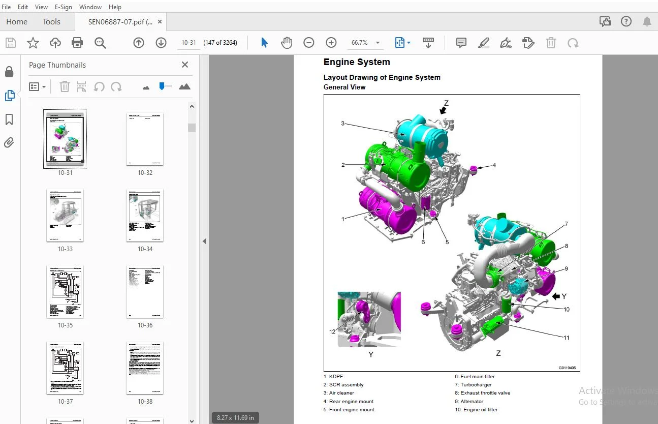
Engine System 10-31
Layout Drawing of Engine System 10-31
Engine Control System 10-33
Automatic Idle Stop System 10-39
Component Parts of Engine System 10-42
Cooling System 10-52
Layout Drawing of Cooling System 10-52
Cooling Fan Control System 10-54
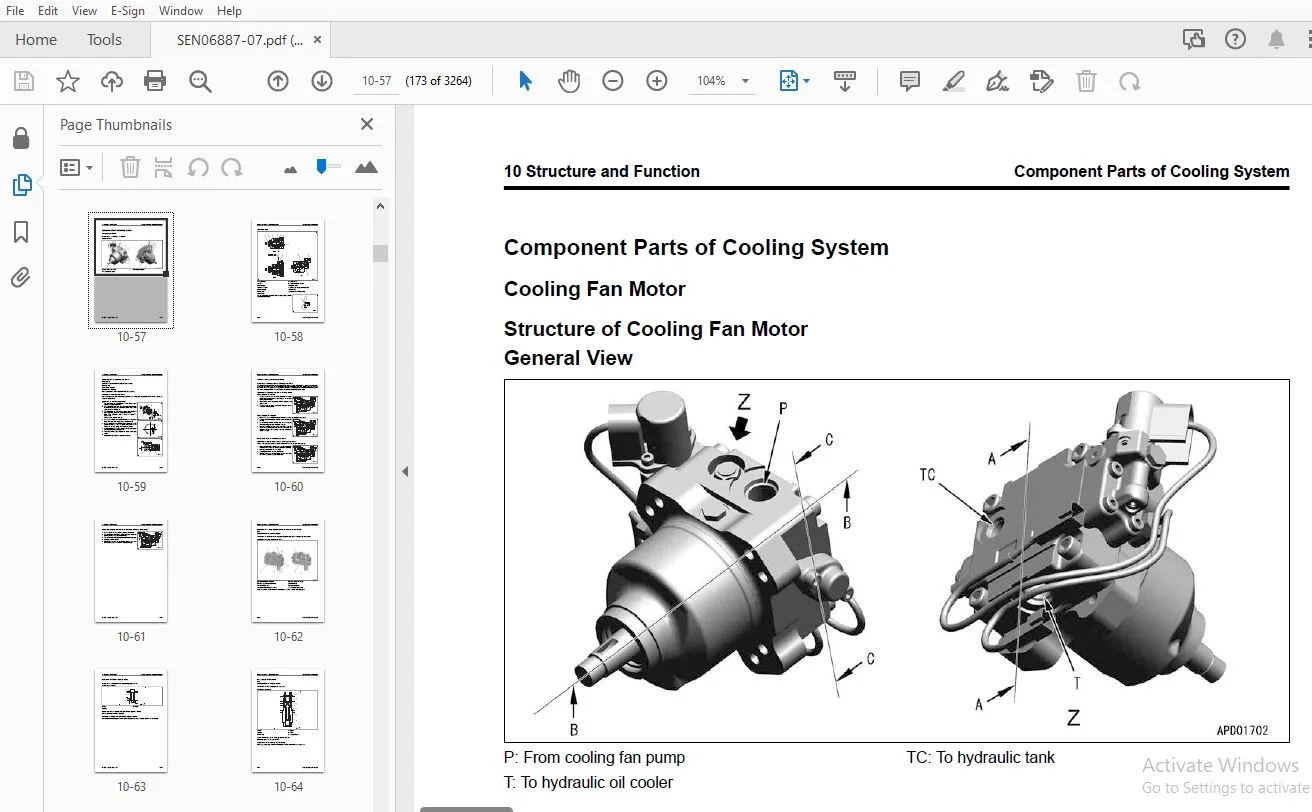
Component Parts of Cooling System 10-57
Control System 10-66
Index 00 Index and Foreword
00-2 D51EXI-24E0, D51PXI-24E0
Layout Drawing of Control System 10-66
Machine Monitor System 10-67
KOMTRAX System 10-68
Component Parts of Control System 10-69
Hydraulic System 10-107
Layout Drawing of Hydraulic System 10-107
CLSS 10-108
Component Parts of Hydraulic System 10-111
Power Train System 10-143
Layout Drawing of HST System 10-143
Operation of HST System 10-144
Steering and Brake Control System 10-146
HST Control System 10-148
Parking Brake Control System 10-159
Component Parts of Power Train System 10-162
Work Equipment System 10-198
Work Equipment Control 10-198
Layout Drawing of Front Work Equipment 10-200
Layout Drawing of Fixed Multi-Shank Ripper 10-201
Component Parts of Work Equipment System 10-202
ICT System 10-218
Layout Drawing of ICT System 10-218
System Diagram of ICT Control System 10-220
Blade Control System 10-222
Assist Control System 10-227
Back Grade Mode System 10-229
Cut Control System 10-231
Smooth Start System 10-244
Slip Control System 10-246
Speed Control System 10-248
Straight Travel Correction System 10-250
Quick Surface Control System 10-254
System of Triangulated Surface from AS-BUILT 10-256
2 Surfaces Selection Control System 10-258
Lift Layer Control System 10-260
2D Laser Machine Control System 10-263
Component Parts of ICT System 10-265
Undercarriage and Frame 10-291
Main Frame 10-291
Suspension 10-292
Track Frame and Idler Cushion 10-295
Work Equipment 10-298
Structure of Front Work Equipment 10-298
Structure of Fixed Multi-Shank Ripper 10-299
CAB Related Parts 10-300
ROPS CAB 10-300
CAB Mount 10-302
20 Standard Value Table 20-1
Table of Contents 20-2
Standard Value Table for Engine 20-3
Standard Value Table for Engine: D51EXI-24E0 20-3
Standard Value Table for Engine: D51PXI-24E0 20-7
Standard Value Table for Machine 20-11
Standard Value Table for Machine: D51EXI-24E0 20-11
Standard Value Table for Machine: D51PXI-24E0 20-28
Machine Posture and Procedures to Measure Performance 20-43
30 Testing and Adjusting 30-1
Table of Contents 30-2
00 Index and Foreword Index
D51EXI-24E0, D51PXI-24E0 00-3
Precautions Before Work 30-6
Related Information on Testing and Adjusting 30-7
Differences In Machine Monitor Symbols 30-7
Tools for Testing and Adjusting 30-8
Sketch of Tools for Testing and Adjusting 30-16
Engine and Cooling System 30-21
Examine Engine Speed 30-21
Examine Boost Pressure 30-23
Examine Exhaust Gas Color 30-24
Examine and Adjust Valve Clearance 30-28
Examine Compression Pressure 30-30
Examine Blowby Pressure 30-35
Examine Engine Oil Pressure 30-37
Examine Fuel Pressure 30-38
Examine Fuel Discharge, Return and Leakage 30-43
Bleed Air from Fuel System 30-49
Examine Fuel Circuit for Leakage 30-50
Handle Cylinder Cut-out Mode Operation 30-52
Handle No-Injection Cranking Operation 30-53
Examine and Adjust Air Conditioner Compressor Belt Tension 30-54
Examine KDPF, SCR and Muffler Stack for Looseness and Damage 30-56
Examine Installed Condition of Cylinder Heads and Manifolds 30-57
Examine Engine Piping for Damage and Looseness 30-58
Write Correction for Ash in Soot Accumulation to Engine Controller 30-59
Examine SCR Related Functions 30-61
Clean DEF Tank 30-90
Clean DEF Tank Mounting Part 30-94
Clean DEF Pump 30-95
Power Train 30-101
Examine and Adjust HST Oil Pressure 30-101
Bleed Air from HST Pump 30-106
Examine Outlet Pressure of Solenoid Valve 30-108
Examine Travel Deviation 30-112
Examine Brake Performance Simply 30-114
Examine and Adjust Deceleration/Brake Pedal 30-115
Adjust Parking Brake Lever 30-119
Move Machine When It Cannot Travel 30-121
Undercarriage and Frame 30-124
Examine and Adjust Idler Clearance 30-124
Examine Sprocket Wear 30-126
Examine and Adjust Track Tension 30-127
Hydraulic System 30-129
Release Remained Pressure in Hydraulic Circuit 30-129
Examine and Adjust Work Equipment Circuit Oil Pressure 30-130
Examine and Adjust Oil Pressure in Control Circuit 30-133
Examine Outlet Pressure of EPC Solenoid Valve 30-135
Bleed Air from Work Equipment, Cooling Fan Pump, and Charge Pump 30-137
Examine Cooling Fan Speed 30-138
Examine Cooling Fan Circuit Oil Pressure 30-139
Examine Parts Which Cause Hydraulic Drift of Work Equipment 30-141
Examine Oil Leakage from Work Equipment Cylinder 30-143
Bleed Air from Work Equipment Cylinders 30-146
Work Equipment 30-147
Adjust Work Equipment Lock Lever 30-147
Examine and Adjust Play of Blade Electric Lever 30-149
Electrical System 30-159
Set and Operate Machine Monitor 30-159
How to Start Up KOMTRAX System 30-294
Index 00 Index and Foreword
00-4 D51EXI-24E0, D51PXI-24E0
How to Stop Use of KOMTRAX System 30-300
Adjust After Replacement of HST Controller 30-302
Adjust After Replacement of Electric and Hydraulic Equipment 30-308
Adjust Rearview Camera Angle 30-310
Set Region of Bluetooth® Compatible Radio 30-311
Handle Voltage Circuit of Engine Controller 30-313
Handle Battery Disconnect Switch 30-314
Examine Diodes 30-315
ICT System 30-316
Examine and Adjust ICT Related Devices 30-316
Set and Operate Control Box 30-318
Machine Calibration 30-319
How to Operate Pitch Rod Calibration 30-341
How to Input Wear Volume of Blade Edge and Track Shoes 30-343
Reset Cylinder Stroke End 30-344
How to Operate Manual Machine Calibration 30-346
Examine and Adjust Blade Elevation 30-348
Examine Stroke Sensor for Lift Cylinder 30-351
Examine Stroke Sensor for Tilt Cylinder 30-353
Examine Stroke Sensor for Angle Cylinder 30-355
Examine and Adjust Reset Sensor for Lift Cylinder 30-357
Adjust When ICT Sensor Controller is Replaced 30-358
Adjust After Replacement of IMU Sensor 30-361
How to Adjust When ICT Related Devices are Repaired or Replaced 30-362
Pm Clinic 30-365
Pm Clinic Service 30-365
40 Troubleshooting 40-1
Table of Contents 40-2
Precautions Before Work 40-14
Related Information to Troubleshooting 40-15
General Troubleshooting Points 40-15
Troubleshooting Points for Urea SCR System 40-16
Sequence of Events in Troubleshooting 40-27
Checks Before Troubleshooting 40-29
Inspection Procedure Before Troubleshooting 40-31
Test in Accordance with Testing Procedure 40-33
Preparation for Troubleshooting of Electrical System 40-56
Procedure for Troubleshooting 40-63
Information Shown in Troubleshooting Table 40-66
How to Diagnose Open Circuit of Hydraulic Pressure Sensor System Wiring Harness 40-68
Connectors List 40-71
Connector Layout 40-80
Connector Contact Connection Table 40-89
T-Branch Box and T-Branch Adapter Table 40-136
Fuse Location Table 40-142
Precautions When You Clean and Replace KDPF (KCSF and KDOC) 40-146
Prepare Short Circuit Electrical Connector (For Failure Codes [CA1883] and [CA3135]) 40-150
Failure Code Table 40-152
Troubleshooting by Failure Code (Display of Code) 40-174
Failure Code [6091NX] 40-174
Failure Code [989L00] 40-176
Failure Code [989M00] 40-177
Failure Code [989N00] 40-178
Failure Code [A1U0N3] 40-179
Failure Code [A1U0N4] 40-181
Failure Code [A900FR] 40-183
Failure Code [A900N6] 40-184
Failure Code [A900NY] 40-185
00 Index and Foreword Index
D51EXI-24E0, D51PXI-24E0 00-5
Failure Code [AA10NX] 40-186
Failure Code [AB00KE] 40-188
Failure Code [AQ10MB] 40-190
Failure Code [AS00R2] 40-192
Failure Code [AS00R3] 40-193
Failure Code [AS00R4] 40-194
Failure Code [AS00R5] 40-195
Failure Code [AS00R6] 40-196
Failure Code [AS00ZK] 40-197
Failure Code [AS10KM] 40-198
Failure Code [AS10NR] 40-199
Failure Code [AS10NT] 40-200
Failure Code [B@BAZG] 40-201
Failure Code [B@BCNS] 40-202
Failure Code [B@BCQA] 40-203
Failure Code [B@BCZK] 40-205
Failure Code [B@CRNS] 40-207
Failure Code [B@CRZG] 40-208
Failure Code [CA115] 40-209
Failure Code [CA122] 40-210
Failure Code [CA123] 40-212
Failure Code [CA131] 40-214
Failure Code [CA132] 40-216
Failure Code [CA144] 40-218
Failure Code [CA145] 40-220
Failure Code [CA153] 40-222
Failure Code [CA154] 40-224
Failure Code [CA187] 40-226
Failure Code [CA227] 40-228
Failure Code [CA234] 40-230
Failure Code [CA238] 40-231
Failure Code [CA239] 40-232
Failure Code [CA249] 40-233
Failure Code [CA256] 40-235
Failure Code [CA271] 40-237
Failure Code [CA272] 40-239
Failure Code [CA322] 40-240
Failure Code [CA324] 40-242
Failure Code [CA331] 40-244
Failure Code [CA332] 40-246
Failure Code [CA343] 40-248
Failure Code [CA351] 40-249
Failure Code [CA352] 40-250
Failure Code [CA386] 40-252
Failure Code [CA428] 40-253
Failure Code [CA429] 40-255
Failure Code [CA435] 40-257
Failure Code [CA441] 40-259
Failure Code [CA442] 40-261
Failure Code [CA451] 40-262
Failure Code [CA452] 40-264
Failure Code [CA488] 40-266
Failure Code [CA515] 40-267
Failure Code [CA516] 40-269
Failure Code [CA553] 40-271
Failure Code [CA555] 40-272
Failure Code [CA556] 40-273
Failure Code [CA559] 40-274
Index 00 Index and Foreword
00-6 D51EXI-24E0, D51PXI-24E0
Failure Code [CA689] 40-277
Failure Code [CA691] 40-280
Failure Code [CA692] 40-282
Failure Code [CA697] 40-284
Failure Code [CA698] 40-285
Failure Code [CA731] 40-286
Failure Code [CA741] 40-288
Failure Code [CA742] 40-290
Failure Code [CA743] 40-292
Failure Code [CA778] 40-293
Failure Code [CA1117] 40-298
Failure Code [CA1664] 40-300
Failure Code [CA1669] 40-302
Failure Code [CA1673] 40-303
Failure Code [CA1677] 40-304
Failure Code [CA1678] 40-305
Failure Code [CA1682] 40-306
Failure Code [CA1683] 40-310
Failure Code [CA1684] 40-312
Failure Code [CA1686] 40-314
Failure Code [CA1695] 40-315
Failure Code [CA1696] 40-316
Failure Code [CA1712] 40-318
Failure Code [CA1713] 40-321
Failure Code [CA1714] 40-323
Failure Code [CA1715] 40-324
Failure Code [CA1776] 40-325
Failure Code [CA1777] 40-328
Failure Code [CA1843] 40-331
Failure Code [CA1844] 40-334
Failure Code [CA1879] 40-337
Failure Code [CA1881] 40-339
Failure Code [CA1883] 40-341
Failure Code [CA1885] 40-344
Failure Code [CA1887] 40-346
Failure Code [CA1921] 40-348
Failure Code [CA1922] 40-351
Failure Code [CA1942] 40-356
Failure Code [CA1993] 40-357
Failure Code [CA2185] 40-360
Failure Code [CA2186] 40-362
Failure Code [CA2311] 40-364
Failure Code [CA2373] 40-365
Failure Code [CA2374] 40-367
Failure Code [CA2554] 40-369
Failure Code [CA2555] 40-371
Failure Code [CA2556] 40-374
Failure Code [CA2639] 40-377
Failure Code [CA2771] 40-379
Failure Code [CA2973] 40-383
Failure Code [CA2976] 40-384
Failure Code [CA3133] 40-386
Failure Code [CA3134] 40-388
Failure Code [CA3135] 40-390
Failure Code [CA3142] 40-393
Failure Code [CA3143] 40-394
Failure Code [CA3144] 40-395
Failure Code [CA3146] 40-397
00 Index and Foreword Index
D51EXI-24E0, D51PXI-24E0 00-7
Failure Code [CA3147] 40-398
Failure Code [CA3148] 40-399
Failure Code [CA3151] 40-401
Failure Code [CA3165] 40-409
Failure Code [CA3229] 40-411
Failure Code [CA3231] 40-413
Failure Code [CA3232] 40-415
Failure Code [CA3235] 40-419
Failure Code [CA3239] 40-421
Failure Code [CA3241] 40-424
Failure Code [CA3242] 40-427
Failure Code [CA3251] 40-430
Failure Code [CA3253] 40-432
Failure Code [CA3254] 40-435
Failure Code [CA3255] 40-437
Failure Code [CA3256] 40-440
Failure Code [CA3311] 40-442
Failure Code [CA3312] 40-444
Failure Code [CA3313] 40-447
Failure Code [CA3314] 40-448
Failure Code [CA3315] 40-449
Failure Code [CA3316] 40-452
Failure Code [CA3317] 40-453
Failure Code [CA3318] 40-454
Failure Code [CA3319] 40-457
Failure Code [CA3321] 40-458
Failure Code [CA3322] 40-460
Failure Code [CA3497] 40-462
Failure Code [CA3498] 40-463
Failure Code [CA3545] 40-464
Failure Code [CA3547] 40-466
Failure Code [CA3558] 40-467
Failure Code [CA3559] 40-469
Failure Code [CA3562] 40-471
Failure Code [CA3563] 40-473
Failure Code [CA3567] 40-476
Failure Code [CA3568] 40-480
Failure Code [CA3571] 40-486
Failure Code [CA3572] 40-488
Failure Code [CA3574] 40-490
Failure Code [CA3575] 40-493
Failure Code [CA3577] 40-495
Failure Code [CA3578] 40-497
Failure Code [CA3583] 40-499
Failure Code [CA3596] 40-501
Failure Code [CA3649] 40-505
Failure Code [CA3681] 40-507
Failure Code [CA3682] 40-512
Failure Code [CA3713] 40-517
Failure Code [CA3717] 40-520
Failure Code [CA3718] 40-521
Failure Code [CA3725] 40-522
Failure Code [CA3741] 40-525
Failure Code [CA3748] 40-526
Failure Code [CA3866] 40-528
Failure Code [CA3868] 40-531
Failure Code [CA4151] 40-535
Failure Code [CA4152] 40-539
Index 00 Index and Foreword
00-8 D51EXI-24E0, D51PXI-24E0
Failure Code [CA4155] 40-543
Failure Code [CA4156] 40-546
Failure Code [CA4157] 40-549
Failure Code [CA4158] 40-551
Failure Code [CA4159] 40-552
Failure Code [CA4161] 40-553
Failure Code [CA4162] 40-556
Failure Code [CA4163] 40-559
Failure Code [CA4164] 40-561
Failure Code [CA4165] 40-563
Failure Code [CA4166] 40-565
Failure Code [CA4168] 40-566
Failure Code [CA4169] 40-569
Failure Code [CA4171] 40-571
Failure Code [CA4249] 40-573
Failure Code [CA4251] 40-575
Failure Code [CA4259] 40-577
Failure Code [CA4261] 40-580
Failure Code [CA4277] 40-583
Failure Code [CA4459] 40-587
Failure Code [CA4461] 40-589
Failure Code [CA4731] 40-592
Failure Code [CA4732] 40-593
Failure Code [CA4739] 40-594
Failure Code [CA4768] 40-595
Failure Code [CA4769] 40-597
Failure Code [CA4842] 40-600
Failure Code [CA4952] 40-603
Failure Code [CA5115] 40-605
Failure Code [CA5179] 40-608
Failure Code [CA5181] 40-610
Failure Code [CA5271] 40-612
Failure Code [CA5272] 40-614
Failure Code [CA5273] 40-616
Failure Code [CA5274] 40-618
Failure Code [CA5275] 40-620
Failure Code [CA5276] 40-622
Failure Code [CA5383] 40-624
Failure Code [CA5631] 40-626
Failure Code [CA5632] 40-628
Failure Code [CA5655] 40-629
Failure Code [CA5689] 40-635
Failure Code [CA5715] 40-637
Failure Code [CA5716] 40-640
Failure Code [CA5838] 40-643
Failure Code [CA5864] 40-645
Failure Code [CA5865] 40-647
Failure Code [CA5938] 40-649
Failure Code [CA6771] 40-651
Failure Code [D130KA] 40-656
Failure Code [D130KB] 40-659
Failure Code [D130KY] 40-661
Failure Code [D19DKA] 40-663
Failure Code [D19DKB] 40-665
Failure Code [D19DKY] 40-667
Failure Code [D19JKZ] 40-670
Failure Code [D19UKA] 40-673
Failure Code [D19UKB] 40-675
00 Index and Foreword Index
D51EXI-24E0, D51PXI-24E0 00-9
Failure Code [D19UMC] 40-677
Failure Code [D811MC] 40-679
Failure Code [D862KA] 40-680
Failure Code [D8ALKA] 40-681
Failure Code [D8ALKB] 40-685
Failure Code [D8AQKR] 40-688
Failure Code [D8G1KT] 40-690
Failure Code [D8G6KT] 40-691
Failure Code [DAF0MB] 40-692
Failure Code [DAF0MC] 40-693
Failure Code [DAF8KB] 40-694
Failure Code [DAF9KQ] 40-696
Failure Code [DAFGMC] 40-697
Failure Code [DAFLKA] 40-698
Failure Code [DAFLKB] 40-700
Failure Code [DAFQKR] 40-702
Failure Code [DAJ000] 40-703
Failure Code [DAJ0KQ] 40-704
Failure Code [DAJ0KT] 40-705
Failure Code [DAJ0MC] 40-706
Failure Code [DAJ1KK] 40-707
Failure Code [DAJ2KK] 40-709
Failure Code [DAJ2KT] 40-711
Failure Code [DAJ5KK] 40-712
Failure Code [DAJ6KK] 40-715
Failure Code [DAJLKA] 40-717
Failure Code [DAJLKB] 40-719
Failure Code [DAJPMA] 40-721
Failure Code [DAJQKR] 40-722
Failure Code [DAJRKR] 40-723
Failure Code [DB2QKR] 40-724
Failure Code [DB2RKR] 40-729
Failure Code [DBR0KT] 40-735
Failure Code [DBR0MC] 40-736
Failure Code [DBR1KK] 40-737
Failure Code [DBR2KK] 40-740
Failure Code [DBR5KK] 40-743
Failure Code [DBRLKA] 40-745
Failure Code [DBRLKB] 40-747
Failure Code [DBRPMA] 40-749
Failure Code [DBRQKR] 40-750
Failure Code [DBRRKR] 40-752
Failure Code [DBU0KR] 40-753
Failure Code [DBUSKR] 40-754
Failure Code [DBUTKA] 40-759
Failure Code [DBUTKN] 40-761
Failure Code [DBUTMA] 40-763
Failure Code [DBUUKA] 40-764
Failure Code [DBUUKN] 40-766
Failure Code [DD12KA] 40-768
Failure Code [DD12KB] 40-770
Failure Code [DD13KA] 40-772
Failure Code [DD13KB] 40-774
Failure Code [DD14KA] 40-776
Failure Code [DD14KB] 40-778
Failure Code [DDKAKA] 40-780
Failure Code [DDKAKB] 40-782
Failure Code [DDKFL4] 40-784
Index 00 Index and Foreword
00-10 D51EXI-24E0, D51PXI-24E0
Failure Code [DDKGL4] 40-786
Failure Code [DDKHKA] 40-788
Failure Code [DDKHKB] 40-790
Failure Code [DDKQKA] 40-792
Failure Code [DDKQKB] 40-794
Failure Code [DDKRKA] 40-796
Failure Code [DDKRKB] 40-798
Failure Code [DDKSKA] 40-800
Failure Code [DDKSKB] 40-802
Failure Code [DDNLKA] 40-804
Failure Code [DDNLKB] 40-806
Failure Code [DDP6KA] 40-808
Failure Code [DDP6KB] 40-811
Failure Code [DDP6MA] 40-813
Failure Code [DDU1FS] 40-815
Failure Code [DDU1KA] 40-817
Failure Code [DDU1KY] 40-820
Failure Code [DFA4KX] 40-822
Failure Code [DFA4KZ] 40-823
Failure Code [DFA4L8] 40-824
Failure Code [DFA5KA] 40-825
Failure Code [DFA5KB] 40-828
Failure Code [DFA6KA] 40-831
Failure Code [DFA6KB] 40-834
Failure Code [DFA7KX] 40-837
Failure Code [DFA7KZ] 40-838
Failure Code [DFA7L8] 40-839
Failure Code [DFA8KA] 40-840
Failure Code [DFA8KB] 40-843
Failure Code [DFA9KA] 40-846
Failure Code [DFA9KB] 40-849
Failure Code [DGS1KA] 40-852
Failure Code [DGS1KX] 40-855
Failure Code [DH21KA] 40-856
Failure Code [DH21KB] 40-858
Failure Code [DHA4KA] 40-860
Failure Code [DHAAMA] 40-862
Failure Code [DHACMA] 40-864
Failure Code [DHH7KA] 40-866
Failure Code [DHH7KB] 40-869
Failure Code [DHH8KA] 40-871
Failure Code [DHH8KB] 40-874
Failure Code [DHH9KA] 40-876
Failure Code [DHH9KB] 40-879
Failure Code [DHHAKA] 40-881
Failure Code [DHHAKB] 40-884
Failure Code [DHRUKA] 40-886
Failure Code [DHRUKB] 40-888
Failure Code [DHRVKA] 40-890
Failure Code [DHRVKB] 40-892
Failure Code [DK30KA] (Applicable Machine: 20001 to 20396) 40-894
Failure Code [DK30KA] (Applicable Machine: 20397 and up) 40-897
Failure Code [DK30KB] (Applicable Machine: 20001 to 20396) 40-900
Failure Code [DK30KB] (Applicable Machine: 20397 and up) 40-902
Failure Code [DK30KX] 40-904
Failure Code [DK30KZ] 40-905
Failure Code [DK30L8] 40-906
Failure Code [DK31KA] (Applicable Machine: 20001 to 20396) 40-907
00 Index and Foreword Index
D51EXI-24E0, D51PXI-24E0 00-11
Failure Code [DK31KA] (Applicable Machine: 20397 and up) 40-910
Failure Code [DK31KB] (Applicable Machine: 20001 to 20396) 40-913
Failure Code [DK31KB] (Applicable Machine: 20397 and up) 40-915
Failure Code [DK40KA] 40-917
Failure Code [DK40KB] 40-920
Failure Code [DK55KX] 40-922
Failure Code [DK55KZ] 40-923
Failure Code [DK55L8] 40-924
Failure Code [DK56KA] (Applicable Machine: 20001 to 20396) 40-925
Failure Code [DK56KA] (Applicable Machine: 20397 and up) 40-928
Failure Code [DK56KB] (Applicable Machine: 20001 to 20396) 40-931
Failure Code [DK56KB] (Applicable Machine: 20397 and up) 40-933
Failure Code [DK57KA] (Applicable Machine: 20001 to 20396) 40-935
Failure Code [DK57KA] (Applicable Machine: 20397 and up) 40-938
Failure Code [DK57KB] (Applicable Machine: 20001 to 20396) 40-941
Failure Code [DK57KB] (Applicable Machine: 20397 and up) 40-943
Failure Code [DK80KA] 40-945
Failure Code [DK80KR] 40-948
Failure Code [DK80KT] 40-953
Failure Code [DKS0L8] 40-956
Failure Code [DKS1KA] 40-957
Failure Code [DKS1KB] 40-959
Failure Code [DKS2KA] 40-961
Failure Code [DKS2KB] 40-963
Failure Code [DKS3KA] 40-965
Failure Code [DKS3KB] 40-967
Failure Code [DKS3MB] 40-969
Failure Code [DKS4L8] 40-971
Failure Code [DKS5KA] 40-972
Failure Code [DKS5KB] 40-974
Failure Code [DKS6KA] 40-976
Failure Code [DKS6KB] 40-978
Failure Code [DKS7MB] 40-980
Failure Code [DKSCL8] 40-981
Failure Code [DKSDKA] 40-982
Failure Code [DKSDKB] 40-984
Failure Code [DKSEKA] 40-986
Failure Code [DKSEKB] 40-988
Failure Code [DKSFKA] 40-990
Failure Code [DKSFKB] 40-992
Failure Code [DKSFMB] 40-993
Failure Code [DLM0KX] 40-994
Failure Code [DLM0MA] 40-995
Failure Code [DLM1KA] 40-996
Failure Code [DLM1KB] 40-998
Failure Code [DLM1MA] 40-1000
Failure Code [DLM2KA] 40-1001
Failure Code [DLM2KB] 40-1003
Failure Code [DLM2MA] 40-1005
Failure Code [DLM3KA] 40-1006
Failure Code [DLM3KB] 40-1008
Failure Code [DLM3MB] 40-1010
Failure Code [DN21FS] 40-1011
Failure Code [DR21KX] 40-1013
Failure Code [DR31KX] 40-1014
Failure Code [DV20KB] 40-1015
Failure Code [DW4BKA] 40-1017
Failure Code [DW4BKB] 40-1019
Index 00 Index and Foreword
00-12 D51EXI-24E0, D51PXI-24E0
Failure Code [DW4BKY] 40-1021
Failure Code [DW7BKA] 40-1023
Failure Code [DW7BKB] 40-1025
Failure Code [DW7EKA] 40-1027
Failure Code [DW7EKB] 40-1029
Failure Code [DW7EKY] 40-1031
Failure Code [DWN5KA] 40-1033
Failure Code [DWN5KB] 40-1035
Failure Code [DWN5KY] 40-1037
Failure Code [DXA4KA] 40-1039
Failure Code [DXA4KB] 40-1041
Failure Code [DXA4KY] 40-1043
Failure Code [DXA5KA] 40-1045
Failure Code [DXA5KB] 40-1047
Failure Code [DXA5KY] 40-1049
Failure Code [DXA6KA] 40-1051
Failure Code [DXA6KB] 40-1053
Failure Code [DXA6KY] 40-1055
Failure Code [DXA7KA] 40-1057
Failure Code [DXA7KB] 40-1059
Failure Code [DXA7KY] 40-1061
Failure Code [DXHRKA] 40-1063
Failure Code [DXHRKB] 40-1065
Failure Code [DXHRKY] 40-1067
Failure Code [DXHSKA] 40-1069
Failure Code [DXHSKB] 40-1071
Failure Code [DXHSKY] 40-1073
Failure Code [DXHTKA] 40-1075
Failure Code [DXHTKB] 40-1077
Failure Code [DXHTKY] 40-1079
Failure Code [DXHUKA] 40-1081
Failure Code [DXHUKB] 40-1083
Failure Code [DXHUKY] 40-1085
Failure Code [DXJ4KA] 40-1087
Failure Code [DXJ4KB] 40-1089
Failure Code [DXJCKA] 40-1091
Failure Code [DXJCKB] 40-1093
Failure Code [DXJCKY] 40-1095
Failure Code [DXJDKA] 40-1097
Failure Code [DXJDKB] 40-1099
Failure Code [DXJDKY] 40-1101
Failure Code [DXK1KA] 40-1103
Failure Code [DXK1KB] 40-1105
Failure Code [DXK1KY] 40-1107
Failure Code [DXK2KA] 40-1109
Failure Code [DXK2KB] 40-1111
Failure Code [DXK2KY] 40-1113
Failure Code [F311KA] 40-1115
Failure Code [F311KB] 40-1117
Failure Code [F312KA] 40-1119
Failure Code [F312KB] 40-1121
Failure Code [F313KA] 40-1123
Failure Code [F313KB] 40-1125
Failure Code [F314KA] 40-1128
Failure Code [F314KB] 40-1130
Failure Code [F315KB] 40-1132
Failure Code [F315KY] 40-1134
Failure Code [F316KB] 40-1136
00 Index and Foreword Index
D51EXI-24E0, D51PXI-24E0 00-13
Failure Code [F316KY] 40-1138
Failure Code [F318KB] 40-1140
Failure Code [F318KY] 40-1143
Failure Code [F31AKB] 40-1145
Failure Code [F31AKY] 40-1147
Failure Code [F31BKB] 40-1149
Failure Code [F31BKY] 40-1151
Failure Code [F31CKB] 40-1153
Failure Code [F31CKY] 40-1155
Failure Code [F31DKB] 40-1157
Failure Code [F31DKY] 40-1159
Failure Code [F31EKB] 40-1161
Failure Code [F31EKY] 40-1163
Failure Code [F7A0KQ] 40-1165
Failure Code [F7A0KT] 40-1166
Failure Code [F7A1KK] 40-1167
Failure Code [F7ALKB] 40-1170
Failure Code [F7AQKR] 40-1172
Failure Code [F7ASKA] 40-1173
Failure Code [FE0AKA] 40-1175
Failure Code [FS10ZE] 40-1177
Troubleshooting of Electrical System (E-Mode) 40-1178
E-1 Engine Does Not Start (Engine Does Not Crank) 40-1178
E-2 Manual Preheating System Does Not Operate 40-1184
E-3 Automatic Preheating System Does Not Operate 40-1187
E-4 While Preheating is in Operation, Preheating Monitor Does Not Come On 40-1189
E-5 When Starting Switch is Turned to ON Position, Machine Monitor Shows Nothing 40-1191
E-6 When Starting Switch is Turned to ON Position (with Engine Stopped), Basic Check Monitor
Comes On 40-1195
E-7 Air Cleaner Clogging Monitor Comes On in Yellow While Engine is in Operation 40-1196
E-8 Charge Level Monitor Comes On in Red While Engine is in Operation 40-1197
E-9 Engine Coolant Temperature Monitor Comes On in Red While Engine is in Operation 40-1198
E-10 Engine Oil Pressure Monitor Comes On in Red While Engine is in Operation 40-1199
E-11 HST Charge Pressure Monitor Comes On in Red While Engine Runs 40-1200
E-12 Hydraulic Oil Temperature Monitor Comes On in Red While Engine is in Operation 40-1201
E-13 HST Oil Filter Clogging Monitor Comes On in Red While Engine Runs 40-1202
E-14 Engine Coolant Temperature Gauge Does Not Show Correct Temperature 40-1203
E-15 DEF Level is Not Shown Correctly 40-1204
E-16 Fuel Gauge Does Not Show Normally 40-1207
E-17 Hydraulic Oil Temperature Gauge Does Not Show Correct Temperature 40-1210
E-18 Operation Mode Does Not Change 40-1211
E-19 When You Operate Customize Switch Does Not Show Customize Screen 40-1212
E-20 When You Change Setting on Customize Screen, Setting of Machine is Not Changed 40-1213
E-21 Service Meter is Not Shown While Starting Switch is in OFF Position 40-1214
E-22 Service Mode Cannot be Selected 40-1215
E-23 Work Equipment Does Not Operate 40-1216
E-24 Foot Heater Does Not Operate 40-1218
E-25 Horn Does Not Sound 40-1224
E-26 Horn Does Not Stop 40-1226
E-27 Backup Alarm Does Not Sound 40-1227
E-28 Backup Alarm Does Not Stop Operation 40-1228
E-29 Headlamp Does Not Come On 40-1229
E-30 Rear Lamp Does Not Come On 40-1233
E-31 No Wiper Operates 40-1236
E-32 Front Wiper Does Not Operate 40-1238
E-33 Rear Wiper Does Not Operate 40-1240
E-34 Left Door Wiper Does Not Operate 40-1242
E-35 Right Door Wiper Does Not Operate 40-1246
Index 00 Index and Foreword
00-14 D51EXI-24E0, D51PXI-24E0
E-36 Front Washer Does Not Operate 40-1250
E-37 Rear Washer Does Not Operate 40-1252
E-38 Left Door Washer Does Not Operate 40-1254
E-39 Right Door Washer Does Not Operate 40-1256
E-40 KOMTRAX System Does Not Operate Correctly 40-1258
E-41 Control Box Shows Message [Waiting for radio link ] 40-1259
E-42 Control Box Shows Message [Waiting for satellites ] 40-1261
E-43 Control Box Shows Message [GPS receiver not connected !] and [Komatsu Machine Trouble]
40-1262
E-44 Control Box Shows Message [Komatsu Machine Trouble] 40-1263
E-45 Control Box Shows Message [Waiting to initialize ] 40-1264
E-46 Control Box Shows Message [System initializing] 40-1265
E-47 Control Box Shows Message [Initializing ] 40-1266
E-48 Control Box Shows Message [Connecting to GPS ] 40-1267
E-49 Elevation Control Key on Control Box Shows Message [Low precisions ] 40-1268
E-50 Control Box Shows Message [Heading Initializing] 40-1269
E-51 Control Box Shows Message [Out of design area ] 40-1270
E-52 Control Box Shows Message [No GPS localization ] 40-1271
E-53 Control Box Shows Message [Loading Design Surface data ] 40-1272
E-54 Control Box Shows Message [Design Surface data invalid] 40-1273
E-55 Control Box Shows Message [Starting switch is OFF] 40-1274
E-56 Control Box Shows Message [Waiting for satellites ] and [Komatsu Machine Trouble] 40-1276
E-57 Control Box Can Not be Turned on 40-1277
E-58 Control Box Does Not Display Intelligent Machine Control Screen 40-1279
E-59 Control Box Does Not Display Bulldozer Image 40-1280
E-60 Control Box Does Not Display Design Surface 40-1281
E-61 Control Box Touch Panel Does Not Respond 40-1282
E-62 Control Box Touch Panel is Inaccurate 40-1283
E-63 Cylinder Stroke Reset Indication Does Not Go Out 40-1284
E-64 AUTO or Strikethrough is Not Shown When AUTO/Manual Switch is Pushed (AUTO or Strikethrough
Goes Out) 40-1285
E-65 When You Examine and Adjust the Blade Elevation, the Value is Different from Actual Machine
40-1287
E-66 Blade Automatic Lower Control Does Not Start While AUTO is Shown 40-1288
E-67 Blade Automatic Raise Control Does Not Start While AUTO is Shown 40-1289
E-68 Blade Automatic Control Function is Not Activated While AUTO is Shown (Blade Automatic Control
Stops) 40-1290
E-69 Finished Surface is Inaccurate (The Average Height of Finished Surface is Lower Than Designed
Surface or Blade Does Not Touch the Surface) 40-1291
E-70 Finished Surface is Inaccurate (The Finished Surface is Not Smooth) 40-1292
E-71 Finished Surface is Inaccurate (When You Finish Slope Horizontally, Steps are Made in Each Direction)
40-1293
E-72 Machine Cannot Escape from Shoes Slip While Blade Automatic Control is Activated (Shoes Frequently
Slips) 40-1295
E-73 Machine Speed Does Not Increase While Blade Automatic Control is Activated 40-1296
E-74 Blade Tilt Angle Does Not Respond with Design Surface While Blade Automatic Control is Activated
40-1297
E-75 Blade Tilts While Blade Automatic Control is Activated 40-1299
E-76 Even After Lift Layer Control is Activated, Measured Lift Layer Terrain Shape Does Not Agree
with Actual Terrain 40-1301
E-77 The Surface Made with Quick Surface Creation Function is Different from the One in Machine
Front Direction, Blade Edge Position 40-1303
E-78 Machine Does Not Travel Straight While Tilt Steering Control is Activated 40-1304
E-79 Control Box Continues to Show Progress Bar in Machine Manual Cal Screen 40-1305
E-80 Engine Hunting Occurs When You Lower the Blade While Ground Line Assist is Activated40-1306
E-81 [Laser Receiver Error (Red)] Icon is Shown on Control Box (2D Laser Machine Control) 40-1307
E-82 [System Error (Red)] Icon is Shown on Control Box (2D Laser Machine Control) 40-1311
E-83 [AUTO (Green)] is Not Shown on Control Box (2D Laser Machine Control) 40-1312
00 Index and Foreword Index
D51EXI-24E0, D51PXI-24E0 00-15
E-84 Finished Surface is Inaccurate (2D Laser Machine Control) 40-1313
E-85 Ground Surface Becomes Rough in Leveling Work (2D Laser Machine Control) 40-1314
E-86 Current Slope Value on Control Box is Different from Actual Value (2D Laser Machine Control)
40-1315
E-87 Automatic Control Cannot be Done If You Change Application (2D Laser Machine Control)40-1316
Troubleshooting for Hydraulic and Mechanical Systems (H Mode) 40-1317
Information Shown in Troubleshooting Table (H-Mode) 40-1317
Failure Mode and Cause Table 40-1318
H-1 R H and L H Tracks Cannot Travel FORWARD and REVERSE (None of the Travel Systems Operate)
40-1324
H-2 R H or L H Track Cannot Travel FORWARD and REVERSE (One of R H or L H Travel Systems
Cannot Operate) 40-1326
H-3 R H or L H Track Cannot Travel FORWARD or REVERSE (Only One of the Travel Systems Cannot
Operate in One Direction) 40-1328
H-4 Travel Speed or Power is Low 40-1330
H-5 Speed Range Does Not Change 40-1332
H-6 Shock is Large When Machine Moves Off or Stops 40-1333
H-7 Travel Deviation is Large 40-1334
H-8 Machine Drift on a Slope is Large 40-1337
H-9 Engine Speed Drops Largely or Engine Stops 40-1339
H-10 Unusual Noise is Heard from Around HST Pump or Motor 40-1341
H-11 HST Oil Temperature (Hydraulic Oil Temperature) Increases Too High 40-1343
H-12 All Work Equipment Do Not Operate 40-1345
H-13 All Work Equipment Speed or Power is Low 40-1347
H-14 Blade Lift Speed or Power is Low 40-1348
H-15 Blade Tilt Speed or Power is Low 40-1350
H-16 Blade Angle Speed or Power is Low 40-1351
H-17 Time Lag of Blade Lift is Large 40-1352
H-18 Hydraulic Drift of Blade Lift is Large 40-1353
H-19 Hydraulic Drift of Tilted Blade is Large 40-1354
H-20 Unusual Noise is Heard from Around Work Equipment and Cooling Fan Pump or Control Valve
40-1355
H-21 Fan Speed is Abnormal (Too High or Low, or Does Not Rotate) 40-1356
H-22 Unusual Noise is Heard from Around Fan 40-1358
Troubleshooting of Engine (S-Mode) 40-1359
Information Shown in Troubleshooting Table (S-Mode) 40-1359
S-1 Engine Does Not Crank When Starting Switch is Turned to Start Position 40-1360
S-2 Engine Cranks but No Exhaust Smoke Comes Out 40-1361
S-3 Fuel is Sprayed but Engine Does Not Start (Misfiring: Engine Cranks but Does Not Start) 40-1362
S-4 Engine Startability is Unsatisfactory 40-1364
S-5 Engine Does Not Pick Up Smoothly 40-1366
S-6 Engine Stops During Operation 40-1368
S-7 Engine Does Not Rotate Smoothly 40-1370
S-8 Engine Lacks Output (or Lacks Power) 40-1371
S-9 Exhaust Color is Black (KDPF Becomes Clogged in Short Time) 40-1373
S-10 Engine Oil Consumption is Excessive 40-1375
S-11 Engine Oil Becomes Dirty Quickly 40-1376
S-12 Fuel Consumption is Excessive 40-1377
S-13 Oil is in Coolant (or Coolant Spurts Back or Coolant Level Goes Down) 40-1378
S-14 Engine Oil Pressure Drops 40-1379
S-15 Fuel Mixes Into Engine Oil 40-1381
S-16 Water Mixes Into Engine Oil (Milky) 40-1382
S-17 Coolant Temperature Increases Too High (Overheat) 40-1383
S-18 Unusual Noise is Heard 40-1384
S-19 Vibration is Excessive 40-1385
S-20 Air Cannot be Bled from Fuel Circuit 40-1386
S-21 Active Regeneration is Done Frequently 40-1387
S-22 Active Regeneration Continues Long 40-1388
Index 00 Index and Foreword
00-16 D51EXI-24E0, D51PXI-24E0
S-23 White Smoke is Exhausted During Active Regeneration 40-1389
S-24 DEF Consumption is Excessive 40-1390
S-25 There is an Unusual Smell (Irritating Odor) 40-1391
S-26 Foreign Materials Enter DEF (DEF Increases) 40-1392
50 Disassembly and Assembly 50-1
Table of Contents 50-2
Precautions Before Work 50-8
Related Information on Disassembly and Assembly 50-9
How to Read This Manual 50-9
Coating Materials List 50-10
Special Tool List 50-15
Sketches of Special Tools 50-34
Prepare 50-46
Drain and Add Coolant 50-46
Drain and Add Hydraulic Oil 50-51
Drain and Add Fuel 50-56
Collect and Refill Refrigerant 50-58
Engine and Cooling System 50-61
Remove and Install Supply Pump Assembly 50-61
Remove and Install Injector Assembly 50-78
Remove and Install Cylinder Head Assembly 50-108
Remove and Install Starter Assembly 50-160
Remove and Install Air Conditioner Compressor Belt 50-165
Remove and Install Alternator Belt 50-170
Remove and Install Automatic Tensioner 50-174
Remove and Install Radiator Assembly 50-176
Remove and Install Hydraulic Oil Cooler Assembly 50-183
Remove and Install Aftercooler Assembly 50-190
Remove and Install Cooling Fan Drive Assembly 50-194
Remove and Install Cooling Fan Motor Assembly 50-206
Remove and Install Engine and HST Pump Assembly 50-212
Remove and Install Engine Front Oil Seal 50-237
Remove and Install Engine Rear Oil Seal 50-241
Remove and Install Engine Hood Assembly 50-253
Remove and Install KDPF Assembly 50-265
Disassemble and Assemble KDPF Assembly 50-276
Remove and Install KDPF and SCR Assembly 50-289
Remove and Install Bellows Pipe Assembly 50-298
Remove and Install Fuel Tank Assembly 50-305
Remove and Install DEF Tank Assembly 50-316
Remove and Install DEF Tank Sensor Flange Assembly 50-332
Remove and Install DEF Tank Sensor 50-337
Remove and Install DEF Tank Strainer 50-345
Remove and Install SCR Assembly 50-347
Remove and Install DEF Injector 50-361
Remove and Install DEF Pump 50-370
Remove and Install DEF Hose 50-380
Remove and Install Air Cleaner Assembly 50-394
Remove and Install Air Conditioner Compressor Assembly 50-396
Remove and Install Air Conditioner Condenser Assembly 50-399
Power Train 50-408
Disassemble and Assemble Final Drive Assembly 50-408
Undercarriage and Frame 50-422
Remove and Install Track Frame Assembly 50-422
Remove and Install Idler Assembly 50-432
Disassemble and Assemble Idler Assembly 50-437
Remove and Install Recoil Spring Assembly 50-444
Disassemble and Assemble Recoil Spring Assembly 50-445
00 Index and Foreword Index
D51EXI-24E0, D51PXI-24E0 00-17
Remove and Install Track Roller Assembly 50-451
Disassemble and Assemble Track Roller Assembly 50-457
Remove and Install Carrier Roller Assembly 50-462
Disassemble and Assemble Carrier Roller Assembly 50-465
Remove and Install Pivot Shaft Assembly 50-469
Separate and Connect Track Assembly 50-471
Separate and Connect PLUS Type Track Assembly 50-476
Disassemble and Assemble Track Assembly Generally 50-478
Disassemble and Assemble PLUS Type Track Assembly Generally 50-496
Disassemble and Assemble One Track Link Assembly in Field (Track Assembly) 50-507
Disassemble and Assemble One Track Link Assembly in Field (PLUS Type Track Assembly) 50-516
Remove and Install Equalizer Bar Assembly 50-523
Remove and Install Equalizer Bar Side Bushing 50-528
Remove and Install Segment Teeth 50-530
Hydraulic System 50-534
Remove and Install Hydraulic Tank Assembly 50-534
Remove and Install Control Valve Assembly 50-554
Work Equipment 50-561
Remove and Install Blade Assembly 50-561
Remove and Install Stroke and Reset Sensing Blade Lift Cylinder Assembly 50-570
Disassemble and Assemble Stroke and Reset Sensing Blade Lift Cylinder Assembly 50-576
Remove and Install Stroke Sensing Blade Tilt Cylinder Assembly 50-590
Disassemble and Assemble Stroke Sensing Blade Tilt Cylinder Assembly 50-600
Remove and Install Stroke Sensing Blade Angle Cylinder Assembly 50-609
Disassemble and Assemble Stroke Sensing Blade Angle Cylinder Assembly 50-615
Remove and Install U-Frame Assembly 50-624
CAB Related Parts 50-630
Remove and Install Operator Cab Assembly 50-630
Remove and Install Operator Cab Glass (Adhered Glass) 50-657
Remove and Install Air Conditioner Unit Assembly 50-665
Remove and Install Receiver Drier 50-678
Remove and Install Operator Seat 50-682
How to Remove and Install Seat Belt 50-687
Remove and Install Foot Heater Assembly 50-690
Disassemble and Assemble Foot Heater Assembly 50-697
Electrical System 50-701
Remove and Install Engine Controller Assembly 50-701
Remove and Install HST Controller Assembly 50-708
Remove and Install Machine Monitor Assembly 50-711
Remove and Install Intake Manifold Pressure and Temperature Sensor 50-715
Remove and Install KDPF Temperature Sensor 50-718
Remove and Install KDPF Differential Pressure Sensor 50-727
Remove and Install SCR Temperature Sensor 50-732
Remove and Install SCR Outlet NOx Sensor 50-741
Remove and Install Gateway Function Controller 50-746
Remove and Install Navigation Controller 50-750
Remove and Install ICT Sensor Controller Assembly 50-759
Remove and Install Control Box 50-762
Remove and Install GNSS Receiver 50-764
Remove and Install GNSS Antenna 50-766
Remove and Install GNSS External Radio Device 50-776
Remove and Install IMU Sensor 50-780
Remove and Install Communication Terminal 50-788
Remove and Install Communication Antenna 50-791
60 Maintenance Standard 60-1
Table of Contents 60-2
Engine and Cooling System 60-3
Maintenance Standard for Engine Mount 60-3
Index 00 Index and Foreword
00-18 D51EXI-24E0, D51PXI-24E0
Maintenance Standard for Damper 60-4
Maintenance Standard for Cooling System 60-5
Maintenance Standard for Cooling Fan Motor 60-6
Maintenance Standard for Hydraulic Oil Cooler Bypass and HST Charge Safety Valve 60-8
Power Train 60-9
Maintenance Standard for HST Pump 60-9
Maintenance Standard for HST Charge Pump 60-13
Maintenance Standard for HST Motor 60-15
Maintenance Standard for Final Drive 60-17
Maintenance Standard for Sprocket for PLUS Type Track Shoes 60-19
Maintenance Standard for Sprocket Tooth Profile Full-Scale Drawing for PLUS Type Track Shoes
60-20
Undercarriage and Frame 60-21
Maintenance Standard for Suspension 60-21
Maintenance Standard for Track Frame and Idler Cushion 60-24
Maintenance Standard for Idler 60-27
Maintenance Standard for Track Roller for PLUS Type Track Shoes (Single Flange Type) 60-29
Maintenance Standard for Track Roller for PLUS Type Track Shoes (Double Flange Type) 60-30
Maintenance Standard for Carrier Roller for PLUS Type Track Shoes 60-32
Maintenance Standard for PLUS Type Track Shoes 60-33
Maintenance Standard for Single Shoes 60-35
Hydraulic System 60-36
Maintenance Standard for Hydraulic Tank 60-36
Maintenance Standard for Work Equipment and Cooling Fan Pump 60-37
Maintenance Standard for Control Valve 60-40
Maintenance Standard for Ripper PPC Valve 60-46
Maintenance Standard for 5-Spool EPC and Solenoid Valve 60-48
Maintenance Standard for Quick Drop Valve 60-50
Work Equipment 60-52
Maintenance Standard for Front Work Equipment 60-52
Maintenance Standard for Cutting Edge and End Bit 60-55
Maintenance Standard for Blade Lift Cylinder 60-56
Maintenance Standard for Blade Tilt Cylinder 60-57
Maintenance Standard for Blade Angle Cylinder 60-58
Maintenance Standard for Fixed Multi-Shank Ripper 60-59
Maintenance Standard for Ripper Lift Cylinder 60-61
CAB Related Parts 60-62
Maintenance Standard for CAB Mount 60-62
Electrical System 60-64
Maintenance Standard for Steering Electric Lever 60-64
80 Appendix 80-1
Table of Contents 80-2
Precautions Before Work 80-3
Air Conditioner System 80-4
Precautions for Refrigerant 80-4
Air Conditioner Component 80-5
Specifications of Air Conditioner 80-8
Structure and Function of Refrigeration Cycle 80-9
Outline of Refrigeration Cycle 80-10
Component Parts of Air Conditioner System 80-12
Air Conditioner Unit 80-12
Component Parts of Air Conditioner Unit 80-14
Compressor 80-17
Condenser 80-18
Receiver Drier 80-20
Explanation of Procedure for Test of and Troubleshooting of Air Conditioner 80-22
Circuit Diagram of Air Conditioner 80-25
System Diagram of Air Conditioner 80-26
00 Index and Foreword Index
D51EXI-24E0, D51PXI-24E0 00-19
Control Function of Air Conditioner 80-27
Locations of Air Conditioner Parts and Layout of Connectors 80-28
Examine Relay 80-32
How to Examine Relay 80-32
Air Conditioner Troubleshooting Chart 1 80-34
Air Conditioner Troubleshooting Chart 2 80-35
Information Shown in Troubleshooting Table 80-38
A-1 Troubleshooting for Condenser Fan 80-39
A-2 Troubleshooting for Compressor and Refrigerant System (Air is Not Cooled) 80-42
A-3 Troubleshooting for Blower Motor System (No Air Comes Out or Air Flow is Abnormal) 80-46
A-4 Troubleshooting for Temperature Control Function 80-49
Troubleshooting by Gauge Pressure 80-53
Connect Service Tool 80-55
How to Connect Service Tool 80-56
Precautions for Disconnection and Connection of Air Conditioner Piping 80-57
Handle Compressor Oil 80-59
90 Circuit Diagrams 90-1
Table of Contents 90-2
Hydraulic Circuit Diagram 90-3
Symbols Used in Hydraulic Circuit Diagram 90-3
Hydraulic Circuit Diagram 90-7
Electrical Circuit Diagram 90-9
Symbols Used in Electric Circuit Diagram 90-9
Electrical Circuit Diagram (Applicable Machine: 20001 to 20396) (1/16) 90-13
Electrical Circuit Diagram (Applicable Machine: 20001 to 20396) (2/16) 90-15
Electrical Circuit Diagram (Applicable Machine: 20001 to 20396) (3/16) 90-17
Electrical Circuit Diagram (Applicable Machine: 20001 to 20396) (4/16) 90-19
Electrical Circuit Diagram (Applicable Machine: 20001 to 20396) (5/16) 90-21
Electrical Circuit Diagram (Applicable Machine: 20001 to 20396) (6/16) 90-23
Electrical Circuit Diagram (Applicable Machine: 20001 to 20396) (7/16) 90-25
Electrical Circuit Diagram (Applicable Machine: 20001 to 20396) (8/16) 90-27
Electrical Circuit Diagram (Applicable Machine: 20001 to 20396) (9/16) 90-29
Electrical Circuit Diagram (Applicable Machine: 20001 to 20396) (10/16) 90-31
Electrical Circuit Diagram (Applicable Machine: 20001 to 20396) (11/16) 90-33
Electrical Circuit Diagram (Applicable Machine: 20001 to 20396) (12/16) 90-35
Electrical Circuit Diagram (Applicable Machine: 20001 to 20396) (13/16) 90-37
Electrical Circuit Diagram (Applicable Machine: 20001 to 20396) (14/16) 90-39
Electrical Circuit Diagram (Applicable Machine: 20001 to 20396) (15/16) 90-41
Electrical Circuit Diagram (Applicable Machine: 20001 to 20396) (16/16) 90-43
Electrical Circuit Diagram (2D Laser Machine Control) (Applicable Machine: 20001 to 20396) 90-45
Electrical Circuit Diagram (Applicable Machine: 20397 and Up) (1/17) 90-47
Electrical Circuit Diagram (Applicable Machine: 20397 and Up) (2/17) 90-49
Electrical Circuit Diagram (Applicable Machine: 20397 and Up) (3/17) 90-51
Electrical Circuit Diagram (Applicable Machine: 20397 and Up) (4/17) 90-53
Electrical Circuit Diagram (Applicable Machine: 20397 and Up) (5/17) 90-55
Electrical Circuit Diagram (Applicable Machine: 20397 and Up) (6/17) 90-57
Electrical Circuit Diagram (Applicable Machine: 20397 and Up) (7/17) 90-59
Electrical Circuit Diagram (Applicable Machine: 20397 and Up) (8/17) 90-61
Electrical Circuit Diagram (Applicable Machine: 20397 and Up) (9/17) 90-63
Electrical Circuit Diagram (Applicable Machine: 20397 and Up) (10/17) 90-65
Electrical Circuit Diagram (Applicable Machine: 20397 and Up) (11/17) 90-67
Electrical Circuit Diagram (Applicable Machine: 20397 and Up) (12/17) 90-69
Electrical Circuit Diagram (Applicable Machine: 20397 and Up) (13/17) 90-71
Electrical Circuit Diagram (Applicable Machine: 20397 and Up) (14/17) 90-73
Electrical Circuit Diagram (Applicable Machine: 20397 and Up) (15/17) 90-75
Electrical Circuit Diagram (Applicable Machine: 20397 and Up) (16/17) 90-77
Electrical Circuit Diagram (Applicable Machine: 20397 and Up) (17/17) 90-79
Index 1
DESCRIPTION:
KOMATSU D51EXi-24E0 D51PXi-24E0 BULLDOZER SHOP MANUAL SEN06887-07 – PDF DOWNLOAD
How to Read the Shop Manual
• Some of the attachments and options described in this shop manual may not be available in some areas. If they are required, consult your Komatsu distributor.
• The materials and specifications are subject to change without notice.
• Shop Manuals are available for “machine part” and “engine part”. For the engine unit, see the shop manual for the machine which has the same engine model.
• Actual machine may differ from the images which are contained in this manual. A typical model is shown in the illustrations of this shop manual.
• The caution lamps, pilot lamps, and symbols of the switches on the machine monitor can be different in accordance with the machine.
• For details of the symbols shown on the machine monitor, see Structure and Operation, “Caution Lamps Shown on Machine Monitor” and “Pilot Lamps Shown on Machine Monitor”.
• For details of the switches of the machine monitor, see Testing and Adjusting, “Set and Operate Machine Monitor”.
• For details of the switches, see the “Operation and Maintenance Manual”.
• All “AdBlue/DEF” shown on the machine monitor is referred to as “DEF” in the shop manual. Some machine monitors installed to the product show “DEF” as “AdBlue/DEF” in the service mode. Thus, be sure to recognize that “DEF” and “AdBlue/DEF” are the same when you read the shop manual.
S.S 28/12/24


