
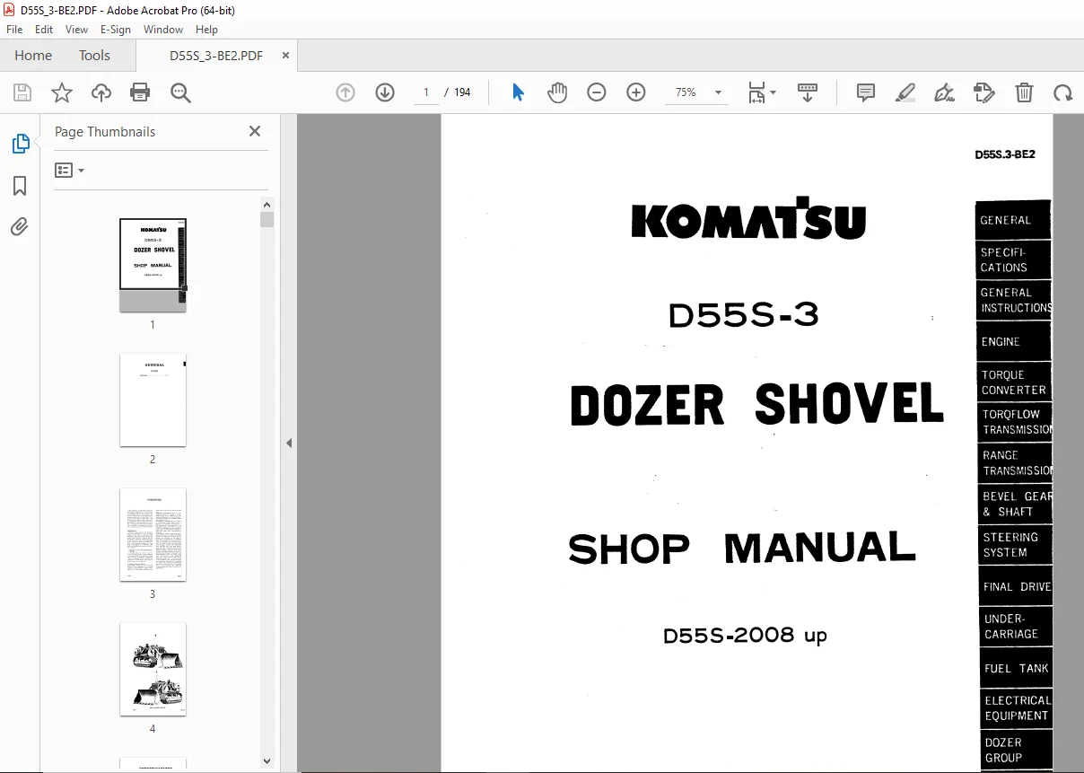
Komatsu D55S-3 Dozer Shovel Shop Manual D55S.3-BE2 PDF
$27.95
Komatsu D55S-3 Dozer Shovel Shop Manual D55S.3-BE2 – PDF DOWNLOAD
- Serial Number : D552-3 2008 UP
Description
Komatsu D55S-3 Dozer Shovel Shop Manual D55S.3-BE2 – PDF DOWNLOAD
FILE DETAILS:
Komatsu D55S-3 Dozer Shovel Shop Manual D55S.3-BE2 – PDF DOWNLOAD
Language : English
Pages : 194
Downloadable : Yes
File Type : PDF
IMAGES PREVIEW OF THE MANUAL:
TABLE OF CONTENTS:
Komatsu D55S-3 Dozer Shovel Shop Manual D55S.3-BE2 – PDF DOWNLOAD
- Serial Number : D552-3 2008 UP
COVER 1
GENERAL 2
FOREWORD 3
SPECIFICATIONS 5
SPECIFICATIONS 6
POWER TRAIN 11
GENEARAL INSTRUTIONS 13
INSTRUCTIONS FOR DISASSEMBLING WORK 14
INSTRUCTIONS FOR RE-ASSEMBLING WORK 14
INSTRUCTIONS FOR ADJUSTING WORK 15
INSTRUCTIONS FOR USE OF HAND TOOLS 15
INSTRUCTIONS FOR HANDLING BEARINGS IN DISASSEMBLING/RE-ASSEMBLING WORK 15
INSTRUCTIONS FOR HANDLING OIL SEALS 16
INSTRUCTIONS FOR HANDLING SNAP RINGS 17
INSTRUCTIONS FOR HANDLING GASKETS AND PACKINGS 17
WEIGHTS OF MAJOR ASSEMBLIES 18
TORQUE LIMIT CHART 18
ENGINE 19
RADIATOR 20
REMOVAL 20
INSTALLATION 22
ENGINE 23
REMOVAL 23
INSTALLATION 25
TORQUE CONVERTER 26
DESCRIPTION 27
REMOVAL 29
DISASSEMBLING 31
ASSEMBLING 32
INSTALLATION 33
TORQUE TRANSMISSION 34
DESCRIPTION 35
POWER TRANSMITTING GROUP 35
A OPERATING PRINCIPLE OF THE PLANETARY GEARING 35
B CONSTRUCTION AND FUNCTION 38
C SELECTIVE PATHS OF POWER THROUGH TRANSMISSION 39
REMOVAL 44
DISASSEMBLING 46
CLEANING AND INSPECTION 53
ASSEMBLING 53
INSTALLATION 54
CONTROL VALVE 55
DESCRIPTION 55
A VALVE FUNCTION 56
B HYDRAULIC OIL FLOWS 56
C TORQUE CONVERTER INLET RELIEF VALVE 59
D TRANSMISSION LUBRICATION RELIEF VALVE 59
DISASSEMBLING 60
CLEANING AND INSPECTION 62
RANGE TRANSMISSION 63
DESCRIPTION 64
A CONSTRUCTION OF RANGE TRANSMISSION 64
B SHIFTER FORK 66
C INTERLOCK 67
REMOVAL 68
DISASSEMBLING 69
CLEANING AND INSPECTION 72
ASSEMBLING 72
INSTALLATION 72
RANGE TRANSMISSION SHIFTER 73
REMOVAL 73
DISASSEMBLING 74
CLEANING AND INSPECTION 76
ASSEMBLING 76
INSTALLATION 76
BEVEL GEAR AND BEVEL GEAR SHAFT 77
DESCRIPTION 78
REMOVAL 79
DISASSEMBLING 80
CLEANING AND INSPECTION 82
ASSEMBLING 83
INSTALLATION 83
ADJUSTMENT 84
TOOTH CONTACT ADJUSTMENT 85
STEERING SYSTEM 86
STEERING CLUTCHES AND BRAKES 87
DESCRIPTION 87
A STEERING CLUTCHES 87
B STEERING BRAKES 89
REMOVAL 90
DISASSEMBLING 92
CLEANING AND INSPECTION 93
ASSEMBLING 94
INSTALLATION 94
ADJUSTMENT 94
STEERING CONTROL VALVE 95
DESCRIPTION 95
REMOVAL 97
DISASSEMBLING 98
CLEANING AND INSPECTION 100
ASSEMBLING 100
INSTALLATION 100
ADJUSTMENT 101
FINAL DRIVE 102
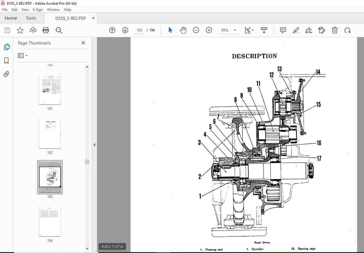
DESCRIPTION 103
REMOVAL 105
DISASSEMBLING 106
CLEANING AND INSPECTION 111
ASSEMBLING 111
UNDERCARRIAGE 112
GENERAL 113
TRACK FRAME 114
DESCRIPTION 114
REMOVAL 115
INSTALLATION 116
RECOIL SPRING 117
DESCRIPTION 117
REMOVAL 117
DISASSEMBLING 118
INSPECTION 119
ASSEMBLING 120
FRONT IDLER 121
DESCRIPTION 121
REMOVAL 122
DISASSEMBLING 122
CLEANING AND INSPECTION 123
ASSEMBLING 124
INSTALLATION 124
CARRIER ROLLER 125
DESCRIPTION 125
REMOVAL 126
DISASSEMBLING 127
CLEANING AND INSPECTION 128
INSTALLATION 128
TRACK ROLLERS 129
DESCRIPTION 129
REMOVAL 129
DISASSEMBLING 130
CLEANING AND INSPECTION 131
INSTALLATION 131
TRACKS 132
DESCRIPTION 132
REMOVAL 133
DISASSEMBLING 134
INSPECTION 134
ASSEMBLING 134
SUSPENSION 135
DESCRIPTION 135
REMOVAL 136
INSPECTION 136
INSTALLATION 136
FUEL TANK 137
DESCRIPTION 138
REMOVAL 139
DISASSEMBLING 139
CLEANING AND INSPECTION 140
ASSEMBLING 140
ELECTRICAL EQUIPMENT 141
ELECTRICAL EQUIPMENT 142
DOZER GROUP 143
DESCRIPTION 144
SAFETY DEVICE FOR SHOVEL ATTACHMENT 145
REMOVAL 147
DISASSEMBLING 148
INSPECTION 149
ASSEMBLING 149
ADJUSTMENT 149
A KICKOUT ADJUSTMENT 149
B POSITION ADJUSTMENT 150
HYDRAULIC SYSTEM 151
GENERAL 152
HYDRAULIC TANK 153
DESCRIPTION 153
CONTROL VALVE 154
DESCRIPTION 154
REMOVAL 158
DISASSEMBLING 159
CLEANING AND INSPECTION 161
INSTALLATION 161
ADJUSTMENT FOR HYDRAULIC PRESSURE 162
HYDRAULIC PUMP 163
DESCRIPTION 163
HYDRAULIC FILTER 164
DESCRIPTION 164
REMOVAL 164
DISASSEMBLING 165
CLEANING AND INSPECTION 166
ASSEMBLING 166
LIFT CYLINDER 167
DESCRIPTION 167
REMOVAL 168
DISASSEMBLING 169
CLEAN AND INSPECTION 170
ASSEMBLING 170
TILT CYLINDER 171
DESCRIPTION 171
REMOVAL 172
DISASSEMBLING 173
ASSEMBLING 174
SIDE FRAME 175
DESCRIPTION 176
REMOVAL 177
INSTALLATION 182
MAINTENANCE STANDARDS 183
MAINTENANCE STANDARDS 184
DESCRIPTION:
Komatsu D55S-3 Dozer Shovel Shop Manual D55S.3-BE2 – PDF DOWNLOAD
- Serial Number : D552-3 2008 UP
- FOREWORD
This MANUAL is published for the in- formation and guidance of shop personal charged with the task of servicing the KOMATSU D55S-3 Dozer Shovel, and provides instructions to be adhered to in disassembling and re-assembling ma- chines of this model in the shop. The instructions are given mainly in the form of procedures, and, in each section of the MANUAL, are proceeded by an out- line description of each major component in respect to mechanical construction, function and other pertinent items. - TERMINOLOGY
Effort has been made in the preparation of this MANUAL to use the most common shop terms in order to avoid ambiguity and equivocation. Some key terms used, however, require precise agreement in advance between the writer and the reader as to their meanings, as the clarity of what are aimed at in shop work depends largely on these terms. Throughout this MANUAL, the major key terms are used with following meanings. - (1) Clockwise (C. W.) and Counterclockwise (C.C.W.)
A circular direction, C. W. or C. C. W., is in the mind of the viewer standing in front and ahead of the machine, except when a driven component is discussed. Such a component as the oil pump, the component is considered singly and as viewed from its driving side. - (2) Terms of Servicing Criteria
BASIC SIZE: This term is universally defined as the theoretical or nominal standard size (diameter, length, thick- ness, etc.) from which variations are
made, and is used in this sense through- out. - ASSEMBLY STANDARD: This is a dimensional value or a range of dimensional values to be adhered to in assembling components. An assemblage is required to satisfy the assembly standard specified for it.
- STANDARD CLEARANCE: This refers to a clearance range, within which a distance of separation occurring in a full assembly or sub-assembly of re- placement parts must take its value. Such an assembly or sub-assembly is permitted to be installed or mounted in place only when this requirement is satisfied.
- CLEARANCE LIMIT (maximum allow- able clearance): A running clearance between a shaft and its hole, for in- stance, will increase as the shaft or hole wears progressively. A clearance limit is provided for each critical or important clearance and, if such a clearance is found to have increased upon disassembling beyond the clearance limit specified for it, the parts associated with that clearance must be corrected to take a value within the limit.
- SERVICE LIMIT: An extra stock is pro- vided in some parts subject to wear, so that these parts may be repaired upon disassembling. There are many such parts that can be re-used repeatedly until their extra stock is used up by grinding, cutting, etc. A service limit is the minimum or the maximum dimension (thickness, diameter, etc.) specified for such a part. Any part found to have exceeded its service limit is not repair. able: its serviceability has ended and a replacement part must be used in re- assembling.
G.B 21/12/24



