
Komatsu D61EX-15 D619X-15 Shop Manual WE051Z0002 – PDF DOWNLOAD
$34.95
Komatsu D61EX-15 D619X-15 Shop Manual WE051Z0002 – PDF DOWNLOAD
SERIAL NUMBER
B40001 and up
B40001 and up
Description
Komatsu D61EX-15 D619X-15 Shop Manual WE051Z0002 – PDF DOWNLOAD
FILE DETAILS:
Komatsu D61EX-15 D619X-15 Shop Manual WE051Z0002 – PDF DOWNLOAD
Language : English
Pages : 988
Downloadable : Yes
File Type : PDF
IMAGES PREVIEW OF THE MANUAL:
TABLE OF CONTENTS:
Komatsu D61EX-15 D619X-15 Shop Manual WE051Z0002 – PDF DOWNLOAD
SERIAL NUMBER
B40001 and up
B40001 and up
MAIN MENU 0
COVER 1
TABLE OF GENERAL CONTENTS 4
GENERAL – FOREWARD 11
SAFETY 12
FOREWARD 14
01 GENERAL 33
Specification dimension drawing 34
Specifications 35
Weight table 40
Oil and coolant table 44
10 GENERAL – STRUCTURE AND FUNCTION, MAINTENANCE STANDARD 47
Engine and cooling related components 48
Cooling system 48
Power transmitting system 50
Power train 50
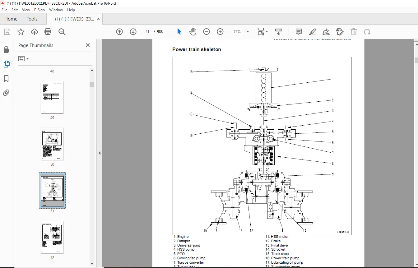
Power train skeleton 51
Overall drawing of power train unit 52
Hydraulic piping diagram of power train 53
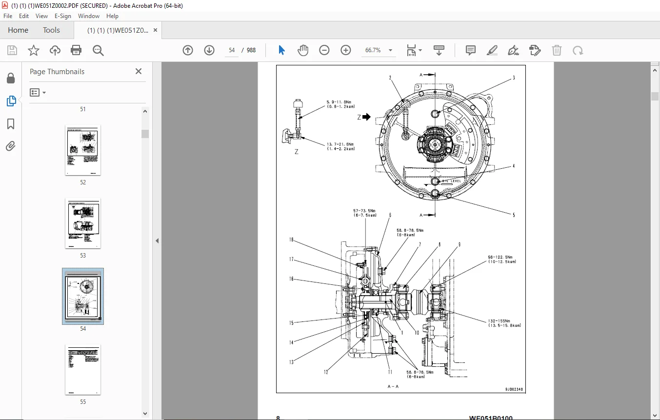
Damper and universal joint 54
Transmission, steering, and brake control 56
Power transmitting system 61
Torque converter and PTO 61
Transmission 66
Transmission ECMV 78
Main relief valve 84
Lubricating oil relief valve 86
Power transmitting system 88
Scavenging pump 88
Power train and lubrication pump 89
HSS system 90
Power transmitting system 94
HSS pump 94
HSS motor112
Power transmitting system120
Bevel gear shaft, HSS, and brake120
Brake valve136
Final drive142
Undercarriage and frame149
Frame assembly149
Suspension150
Track frame and recoil spring154
Idler158
Track roller160
Carrier roller161
Sprocket162
Track shoe164
Hydraulic system168
Layout of hydraulic devices for work equipment168
Work equipment control170
Hydraulic tank and filter172
Solenoid valve174
Accumulator176
Hydraulic cylinder178
Piston valve182
Quick drop valve183
Hydraulic system186
Cooling fan pump186
Cooling fan motor194
PPC valve200
Electric lever (Steering)216
Hydraulic system220
Control valve220
CLSS228
Self-pressure reducing valve255
Work equipment264
Work equipment264
Cutting edge and end bit270
Ripper271
Cab and its attachments272
Cab mount272
Cab273
Air conditioner piping275
Electric system278
Engine control system278
Cooling system control system280
Palm command control system282
PPC lock system284
Component parts of system285
Monitor system290
Monitor panel292
Sensor296
20 TESTING, ADJUSTING & TROUBLESHOOTING301
Standard value table301
Standard value table for engine302
Standard value table for chassis303
Testing and adjusting315
Testing and adjusting (1/2)317
Tools for testing, adjusting and troubleshooting317
Measuring engine speed319
Measuring intake air pressure (boost pressure)321
Measuring exhaust color322
Adjusting valve clearance323
Measuring compression pressure326
Measuring blow-by pressure328
Testing and adjusting fuel injection timing329
Measuring engine oil pressure332
Testing and adjusting air conditioner compressor belt tension333
Adjusting engine speed sensor333
Adjusting fuel control linkage334
Measuring power train oil pressure338
Adjusting transmission speed sensor (replacement procedure)342
Simple method of testing brake performance343
Adjusting brake pedal344
Adjusting parking brake lever346
Emergency escape method when power train has a trouble347
Adjusting idler clearance351
Inspecting wear of sprocket351
Testing and adjusting track shoe tension352
Testing and adjusting work equipment and HSS oil pressure353
Testing control circuit main pres sure357
Measuring PPC valve output pres sure358
Adjusting play of work equipment PPC valve361
Measuring internal leakage of work equipment cylinder362
Adjusting safety lock lever of work equipment363
Releasing residual pressure in work equipment cylinder (If PPC accumulator is not installed)364
Releasing residual pressure in work equipment cylinder (If PPC accumulator is installed)364
Bleeding air from work equipment cylinder365
Measuring fan pump circuit pres sure366
Measuring fan motor speed367
Measuring HSS motor oil leakage368
Bleeding air from fan pump368
Testing and adjusting operator’s cab369
Testing and adjusting (2/2)374
Special functions of monitor panel (EMMS)374
Adjustment method of replaced controller406
Preparatory work for troubleshooting for electric system408
Pm clinic409
Undercarriage troubleshooting report416
Troubleshooting421
Preface422
Points to remember when troubleshooting422
Troubleshooting procedure423
Points to remember when carrying out maintenance424
Checks before troubleshooting431
Classification and procedures of troubleshooting432
Connector arrangement drawing and electric circuit diagram of each system435
Troubleshooting when error code is displayed (Error code) – CONTENTS479
Troubleshooting when error code is displayed (Error code)483
Error code table483
Information described in troubleshooting list486
Error code [1500L0] (Transmission clutch: Double engaging)488
Error code [15SAL1] (Forward clutch: Fill signal is ON when command current is OFF)489
Error code [15SALH] (Forward clutch: Fill signal is OFF when command current is ON)490
Error code [15SBL1] (Reverse clutch: Fill signal is ON when command current is OFF)491
Error code [15SBLH] (Reverse clutch: Fill signal is OFF when command current is ON)492
Error code [15SEL1] (1st clutch: Fill signal is ON when command current is OFF)493
Error code [15SELH] (1st clutch: Fill signal is OFF when command current is ON)494
Error code [15SFL1] (2nd clutch: Fill signal is ON when command current is OFF)495
Error code [15SFLH] (2nd clutch: Fill signal is OFF when command current is ON)496
Error code [15SGL1] (3rd clutch: Fill signal is ON when command current is OFF)497
Error code [15SGLH] (3rd clutch: Fill signal is OFF when command current is ON)498
Error code [A000N1] (Engine: Overrun)499
Error code [AB00MA] (Alternator: Malfunction)500
Error code [B@BAZG] (Engine oil: Oil pressure reduction)501
Error code [B@BCNS] (Coolant: Overheating)502
Error code [B@CENS] (Power train oil: Overheating)503
Error code [B@HANS] (Hydraulic oil: Overheating)504
Error code [D110KA] (Battery relay: Short circuit)505
Error code [D110KB] (Battery relay: Disconnection)506
Error code [D130KA] (Safety relay: Short circuit)508
Error code [D130KB] (Safety relay: Disconnection)510
Error code [D161KA] (Back-up alarm relay: Short circuit)512
Error code [D161KB] (Back-up alarm relay: Disconnection)514
Error code [D182KZ] (Preheater relay coil: Disconnection or short circuit)516
Error code [DAFRKR] (Monitor controller CAN communication: Defective communication (Abnormality in objective component system))518
Error code [DAQ0KK] [DB30KK] (Steering and transmission controller: Source voltage reduction/input)520
Error code [DAQ0KT] (Steering and transmission controller: Abnormality in controller)522
Error code [DAQ5KK] or [DB35KK] (Steering and transmission controller sensor 5 V power supply: Source voltage reduction)523
Error code [DAQ6KK] [DB36KK] (Steering and transmission controller sensor 24 V power supply: Source voltage reduction/input)525
Error code [DAQ9KQ] [DB39KQ] (Steering and transmission controller model collation: Model selection signal inconsistency)526
Error code [DB3RKR] (Steering and transmission controller CAN communication: Defective communication)527
Error code [DB30KK] [DAQ0KK] (Steering and transmission controller: Source voltage reduction/input)529
Error code [DB35KK] [DAQ5KK] (Steering and transmission controller sensor 5 V power supply: Source voltage reduction/input)529
Error code [DB36KK] [DAQ6KK] (Steering and transmission controller sensor 24 V power supply: Source voltage reduction/input)529
Error code [DB39KQ] [DAQ9KQ] (Steering and transmission controller model collation: Model selection signal inconsistency)529
Error code [DD12KA] (Shift up switch: Disconnection)530
Error code [DD12KB] (Shift up switch: Short circuit)532
Error code [DD13KA] (Shift down switch: Disconnection)534
Error code [DD13KB] (Shift down switch: Short circuit)536
Error code [DD14KA] [DDQ2KA] (Travel lock switch: Disconnection)538
Error code [DD14KB] [DDQ2KB] (Travel lock switch: Short circuit)540
Error code [DDE2L6] (Engine oil pressure switch: Signals of engine oil pressure switch are inconsistent with operation state or stop state)542
Error code [DDN7KA] (Pitch control switch: Disconnection)544
Error code [DDN7KB] (Pitch control switch: Short circuit)545
Error code [DDQ2KA] [DD14KA] (Travel lock switch: Disconnection)546
Error code [DDQ2KB] [DD14KB] (Travel lock switch: Short circuit)546
Error code [DGE2KX] (Engine coolant temperature sensor (for high temperature): Input signal is out of normal range)547
Error code [DGE3L6] (Engine coolant temperature sensor: Signals of engine coolant temperature sensor are inconsistent with operation state or stop state)549
Error code [DGS1KX] (Hydraulic oil temperature sensor: Input signal is out of normal range)551
Error code [DK10KX] (Fuel control dial: Input signal is out of normal range)552
Error code [DK12KX] (Deceleration pedal potentiometer: Input signal is out of normal range)554
Error code [DK30KA] (Steering potentiometer 1: Disconnection)556
Error code [DK30KB] (Steering potentiometer 1: Short circuit)558
Error code [DK30KX] (Steering potentiometer 1: Input signal is out of normal range)560
Error code [DK30KZ] (Steering potentiometer 1: Disconnection or short circuit)561
Error code [DK30L8] (Steering potentiometer 1: Disagreement of analog signals)562
Error code [DK31KA] (Steering potentiometer 2: Short circuit)563
Error code [DK31KB] (Steering potentiometer 2: Disconnection)565
Error code [DK40KA] (Brake potentiometer: Short circuit)567
Error code [DK40KB] (Brake potentiometer: Disconnection)569
Error code [DK54KZ] (Governor motor potentiometer: Disconnection or short circuit)571
Error code [DK55KX] (Forward-reverse potentiometer: Input signal is out of normal range)573
Error code [DK55KZ] (Forward-reverse potentiometer 1: Disconnection or short circuit)574
Error code [DK55L8] (Forward-reverse potentiometer: Disagreement of analog signals)575
Error code [DK56KA] (Forward-reverse potentiometer 1: Short circuit)576
Error code [DK56KB] (Forward-reverse potentiometer 1: Disconnection)578
Error code [DK57KA] (Forward-reverse potentiometer 2: Short circuit)580
Error code [DK57KB] (Forward-reverse potentiometer 2: Disconnection)582
Error code [DKH1KA] (Pitch angle sensor: Short circuit)584
Error code [DKH1KB] (Pitch angle sensor: Disconnection)585
Error code [DLE2MA] (Engine speed sensor: Malfunction)587
Error code [DLF1KA] (Transmission output speed sensor: Disconnection)588
Error code [DV00KB] (Buzzer: Short circuit)589
Error code [DW5AKA] (Pitch control solenoid: Disconnection)590
Error code [DW5AKB] (Pitch control solenoid: Short circuit)591
Error code [DW7BKA] (Fan reverse solenoid: Disconnection)592
Error code [DW7BKB] (Fan reverse solenoid: Short circuit)593
Error code [DWN1KA] (HSS EPC solenoid right: Disconnection)594
Error code [DWN1KB] (HSS EPC solenoid right: Short circuit)595
Error code [DWN2KA] (HSS EPC solenoid left: Disconnection)596
Error code [DWN2KB] (HSS EPC solenoid left: Short circuit)597
Error code [DWN5KA] (Fan pump TVC solenoid: Disconnection)598
Error code [DWN5KB] (Fan pump TVC solenoid: Short circuit)599
Error code [DXA0KA] (HSS pump TVC solenoid: Disconnection)600
Error code [DXA0KB] (HSS pump TVC solenoid: Short circuit)601
Error code [DXH4KA] (1st clutch ECMV: Disconnection)602
Error code [DXH4KB] (1st clutch ECMV: Short circuit)603
Error code [DXH5KA] (2nd clutch ECMV: Disconnection)604
Error code [DXH5KB] (2nd clutch ECMV: Short circuit)605
Error code [DXH6KA] (3rd clutch ECMV: Disconnection)606
Error code [DXH6KB] (3rd clutch ECMV: Short circuit)607
Error code [DXH7KA] (Reverse clutch ECMV: Disconnection)608
Error code [DXH7KB] (Reverse clutch ECMV: Short circuit)609
Error code [DXH8KA] (Forward clutch ECMV: Disconnection)610
Error code [DXH8KB] (Forward clutch ECMV: Short circuit)611
Error code [DY10K4] (Governor motor: Loss of synchronism)612
Error code [DY10KA] (Governor motor: Disconnection)613
Error code [DY10KB] (Governor motor: Short circuit)614
Error code [DY45KA] (Engine stop solenoid relay: Disconnection)616
Error code [DY45KB] (Engine stop solenoid relay: Short circuit)618
Troubleshooting of electrical system (E-mode) – CONTENTS621
Troubleshooting of electrical system (E-mode)623
Before troubleshooting electrical system (E-mode)623
Information described in troubleshooting list625
E-1 Engine does not start626
E-2 Preheater does not operate631
E-3 No monitor panel lamps light at all when starting switch is turned ON634
E-4 All lamps continue to light on monitor panel when starting switch is turned ON635
E-5 While engine is running, battery charge level warning lamp flashes636
E-6 While engine is operating, an emergency warning item flashes638
E-7 Preheating pilot lamp does not light during preheating642
E-8 Engine coolant temperature gauge does not indicate normally644
E-9 Power train oil temperature gauge does not indicate normally645
E-10 Hydraulic oil temperature gauge does not indicate normally646
E-11 Fuel gauge does not indicate normally647
E-12 Gear speed is indicated incorrectly648
E-13 Indication of preset mode service meter is abnormal648
E-14 Warning lamp does not flash or does not go out648
E-15 Engine speed is indicated incorrectly649
E-16 Transmission speed or travel speed is indicated incorrectly650
E-17 Caution buzzer does not sound or does not stop651
E-18 Auto shift down does not function or it is not released652
E-19 Buzzer cancel switch does not function653
E-20 Information switch does not function655
E-21 Reverse fan rotation and cleaning functions do not operate, or they are not released657
E-22 Preset mode cannot be selected or released659
E-23 Service mode cannot be selected or it is selected errorneously660
E-24 Backup alarm does not sound662
E-25 Headlamp and rear lamp do not light664
E-26 Horn does not sound or does not stop666
E-27 Work equipment lock lever does not function or it cannot be released667
E-28 Wiper malfunction669
E-29 Washing water does not come out681
E-30 Air conditioner does not operate686
Troubleshooting of hydraulic and mechanical system (H-mode) – CONTENTS691
Troubleshooting of hydraulic and mechanical system (H-mode)693
Information described in troubleshooting list693
H-1 No travel power (No drawbar pull)694
H-2 Machine does not move (At 2nd or 3rd speed)695
H-3 Machine does not move in any speed range696
H-4 Machine travels only in one direction forward or in reverse697
H-5 When gear is shifted or travel direction is changed, large time lag is made698
H-6 Machine does not turn (Not turned rightward or leftward)699
H-7 Steering speed or power is low700
H-8 Brake does not work701
H-9 Overheat of power train oil temperature702
H-10 Abnormal sound comes out from around HSS and work equipment pump or HSS motor703
H-11 All work equipment speeds are slow704
H-12 Work equipment does not move705
H-13 Blade lift speed is slow or lacks power706
H-14 Blade tilt speed is slow or lacks power707
H-15 Angling blade speed is slow or lacks power708
H-16 Ripper lift speed is slow or lacks power709
H-17 Excessive hydraulic drift of blade lift710
H-18 Excessive hydraulic drift of blade tilt711
H-19 Excessive hydraulic drift of blade angle712
H-20 Excessive hydraulic drift of ripper lift713
Troubleshooting of engine system (S-mode) – CONTENTS715
Troubleshooting of engine system (S-mode)718
Method of using matrix troubleshooting charts718
S-1 Starting performance is poor (starting always takes time)722
S-2 Engine does not start723
S-3 Engine does not pick up smoothly (follow-up is poor)726
S-4 Engine stopped during operation727
S-5 Engine does not rotate smoothly (hunting)728
S-6 Engine lacks output (or lacks power)729
S-7 Exhaust gas color is black (incomplete combustion)730
S-8 Oil consumption is excessive (or exhaust gas color is blue)731
S-9 Oil becomes contaminated quickly732
S-10 Fuel consumption is excessive733
S-11 Oil is in coolant, coolant spurts back, or coolant level goes down734
S-12 Oil pressure monitor is turned on (drop in oil pressure)735
S-13 Oil level rises (water or fuel in oil)736
S-14 Water temperature becomes too high (overheating)737
S-15 Abnormal noise is made738
S-16 Vibration is excessive739
30 DISASSEMBLY AND ASSEMBLY741
Preface742
How to read this manual742
Standard tightening torque table744
Precautions when performing operation747
List of coatings752
Special tool list754
Sketches of special tools758
Engine related procedures762
Removal and installation of fuel injection pump assembly762
Removal and installation of cylinder head assembly767
Removal and installation of engine front seal774
Removal and installation of engine rear seal775
Removal and installation of engine assembly779
Removal and installation of damper assembly782
Removal and installation of radiator guard assembly786
Removal and installation of radiator and hydraulic oil cooler assembly790
Removal and installation of fan drive assembly793
Removal and installation of fan motor assembly794
Removal and installation of engine hood assembly795
Removal and installation of fuel tank assembly796
Power train800
Removal and installation of PTO, torque converter and transmission assembly800
Disconnection and connection of PTO, torque converter and transmission assembly804
Disassembly and assembly of PTO assembly806
Disassembly and assembly of torque converter assembly811
Disassembly and assembly of TORQFLOW transmission assembly815
Removal and installation of torque converter main relief valve assembly832
Disassembly and assembly of torque converter main relief valve assembly833
Power train836
Removal and installation of power train and lubricating oil pump assembly836
Removal and installation of HSS and work equipment pump assembly838
Removal and installation of scavenging pump assembly839
Removal and installation of HSS motor assembly839
Disassembly and assembly of HSS assembly840
Removal and installation of final drive assembly858
Disassembly and assembly of final drive assembly859
Undercarriage874
Removal and installation of track frame assembly874
Removal and installation of idler assembly876
Disassembly and assembly of idler assembly877
Removal and installation of recoil spring assembly881
Disassembly and assembly of recoil spring assembly882
Removal and installation of track roller assembly885
Disassembly and assembly of track roller assembly886
Removal and installation of carrier roller assembly889
Disassembly and assembly of carrier roller assembly890
Undercarriage894
Check before expanding track shoe assembly894
Expansion (normal), expansion (internal abnormality) and installation of track shoe assembly894
Overall disassembly and overall assembly of track shoe assembly896
Link press-fitting jig dimensions table912
Field disassembly and assembly of one link913
Removal and installation of pivot shaft assembly920
Removal and installation of equalizer bar assembly922
Removal and installation of equalizer bar side bushing923
Removal and installation of segment teeth924
Hydraulic system926
Removal and installation of main control valve assembly926
Assembly of main control valve assembly928
Removal and installation of cooling fan pump assembly931
Removal and installation of work equipment assembly932
Disassembly and assembly of work equipment assembly934
Disassembly and assembly of hydraulic cylinder assembly937
Others944
Removal and installation of operator’s cab assembly944
Removal and installation of operator’s cab glass (stuck glass)949
Removal and installation of ROPS canopy958
Removal and installation of dashboard assembly959
Removal and installation of floor frame assembly960
Removal and installation of steering and transmission controller assembly965
90 OTHERS967
Hydraulic circuit diagram968
Power train hydraulic circuit diagram968
Work equipment hydraulic circuit diagram Power angle power tilt dozer (PAT)970
Work equipment hydraulic circuit diagram Power tilt dozer (PT)972
Electrical circuit diagram974
Electrical circuit diagram (1/6)974
Electrical circuit diagram (2/6)976
Electrical circuit diagram (3/6)978
Electrical circuit diagram (4/6)980
Electrical circuit diagram (5/6)982
Electrical circuit diagram (6/6)984
Cab electrical circuit diagram986
DESCRIPTION:
Komatsu D61EX-15 D619X-15 Shop Manual WE051Z0002 – PDF DOWNLOAD
SERIAL NUMBER
B40001 and up
B40001 and up
Foreword
General
This shop manual has been prepared as an aid to improve the quality of repairs by giving the serviceman an accurate understanding of the product and by showing him the correct way to perform repairs and make judgements. Make sure you understand the contents of this manual and use it to full effect at every opportunity. This shop manual mainly contains the necessary technical information for operations performed in a service workshop. For ease of understanding, the manual is divided into the following chapters; these chapters are further divided into the each main group of components. Structure and function This section explains the structure and function of each component. It serves not only to give an understanding of the structure, but also serves as reference material for troubleshooting. In addition, this section may contain hydraulic circuit diagrams, electric circuit diagrams, and maintenance standards. Testing and adjusting This section explains checks to be made before and after performing repairs, as well as adjustments to be made at completion of the checks and repairs. Troubleshooting charts correlating “Problems” with “Causes” are also included in this section. Disassembly and assembly This section explains the procedures for removing, installing, disassembling and assembling each component, as well as precautions for them. Maintenance standard This section gives the judgment standards for inspection of disassembled parts. The contents of this section may be described in “Structure and function”. Others This section mainly gives hydraulic circuit diagrams and electric circuit diagrams. In addition, this section may give the specifications of attachments and options together.
G.B 13/12/24



