
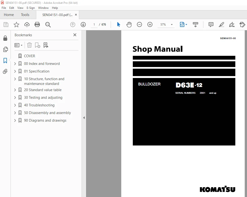
Komatsu D63E-12 Bulldozer Shop Manual SEN04151-00 PDF
$31.95
Komatsu D63E-12 Bulldozer Shop Manual SEN04151-00 – PDF DOWNLOAD
SERIAL NUMBERS 2001 and up
Description
Komatsu D63E-12 Bulldozer Shop Manual SEN04151-00 – PDF DOWNLOAD
FILE DETAILS:
Komatsu D63E-12 Bulldozer Shop Manual SEN04151-00 – PDF DOWNLOAD
Language : English
Pages : 676
Downloadable : Yes
File Type : PDF
DESCRIPTION:
Komatsu D63E-12 Bulldozer Shop Manual SEN04151-00 – PDF DOWNLOAD
SERIAL NUMBERS 2001 and up
How to read the shop manual
1. Composition of shop manual
This shop manual contains the necessary technical information for services performed in a workshop.
For ease of understanding, the manual is divided into the following sections.
00. Index and foreword
This section explains the shop manuals list, table of contents, safety, and basic information.
01. Specification
This section explains the specifications of the machine.
10. Structure, function and maintenance standard
This section explains the structure, function, and maintenance standard values of each component.
The structure and function sub-section explains the structure and function of each component. It
serves not only to give an understanding of the structure, but also serves as reference material for
troubleshooting. The maintenance standard sub-section explains the criteria and remedies for disassembly
and service.
20. Standard value table
This section explains the standard values for new machine and judgement criteria for testing,
adjusting, and troubleshooting. This standard value table is used to check the standard values in
testing and adjusting and to judge parts in troubleshooting.
30. Testing and adjusting
This section explains measuring instruments and measuring methods for testing and adjusting, and
method of adjusting each part. The standard values and judgement criteria for testing and adjusting
are explained in Testing and adjusting.
40. Troubleshooting
This section explains how to find out failed parts and how to repair them. The troubleshooting is
divided by failure modes. The “S mode” of the troubleshooting related to the engine may be also
explained in the Chassis volume and Engine volume. In this case, see the Chassis volume.
50. Disassembly and assembly
This section explains the special tools and procedures for removing, installing, disassembling, and
assembling each component, as well as precautions for them. In addition, tightening torque and
quantity and weight of coating material, oil, grease, and coolant necessary for the work are also
explained.
90. Diagrams and drawings (chassis volume)/Repair and replacement of parts (engine volume)
q Chassis volume
This section gives hydraulic circuit diagrams and electrical circuit diagrams.
q Engine volume
This section explains the method of reproducing, repairing, and replacing parts.
TABLE OF CONTENTS:
Komatsu D63E-12 Bulldozer Shop Manual SEN04151-00 – PDF DOWNLOAD
SERIAL NUMBERS 2001 and up
COVER 1
00 Index and foreword 0
100 Index 2
Composition of shop manual 3
Table of contents 5
200 Foreword and general information 12
Safety notice 13
How to read the shop manual 18
Explanation of terms for maintenance standard 20
Handling of electric equipment and hydraulic component 22
Handling of connectors newly used for engines 31
How to read electric wire code 34
Precautions when carrying out operation 37
Method of disassembling and connecting push-pull type coupler 40
Standard tightening torque table 43
Conversion table 47
01 Specification 0
100 Specification and technical data 54
Specification drawing 55
Specifications 56
Weight table 59
Table of fuel, coolant and lubricants 61
10 Structure, function and maintenance standard 64
100 Engine and cooling system 64
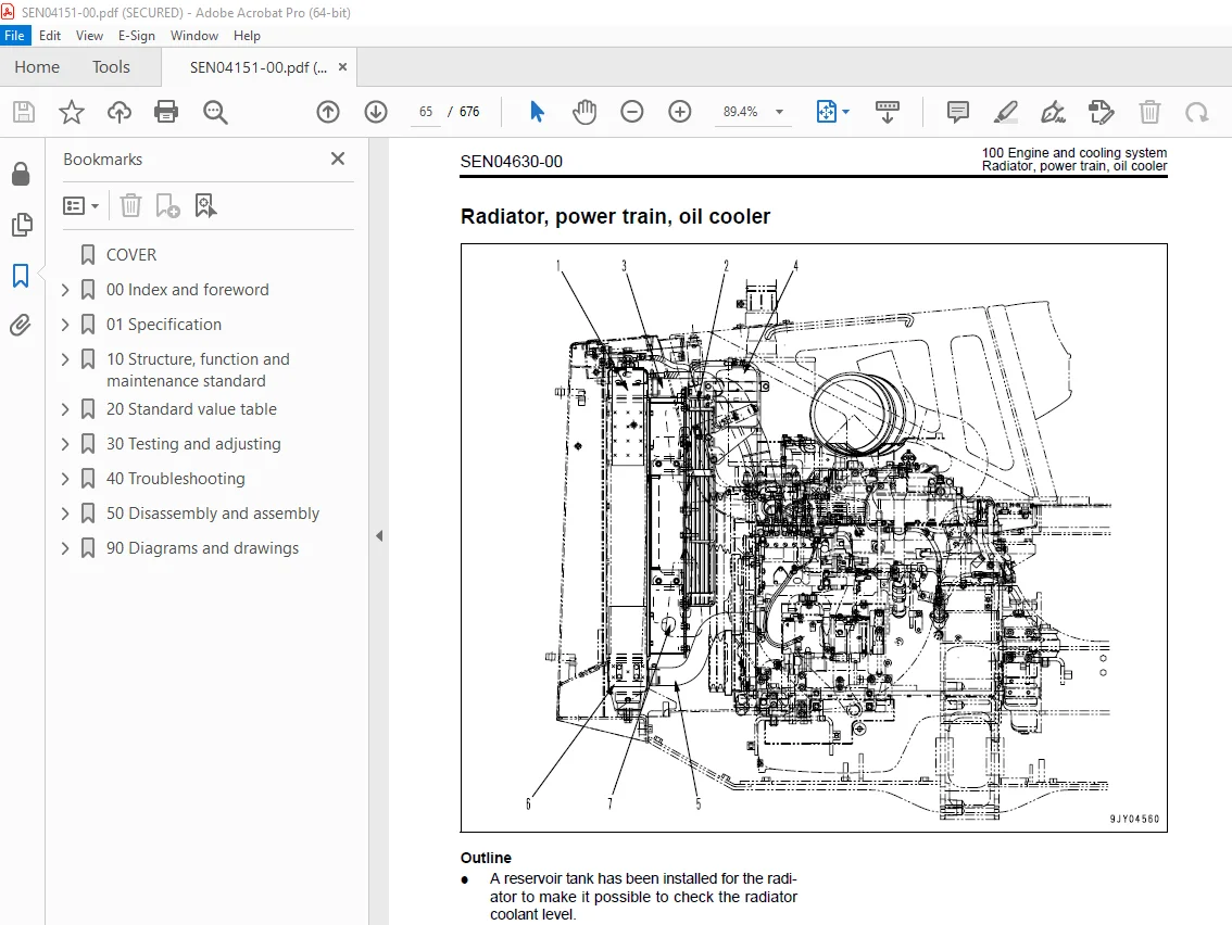
Radiator, power train, oil cooler 65
Engine control 67
210 Power train, Part 1 70
Power train system 71
Power train skeleton 72
Power train unit 73
Power train hydraulic piping diagram 74
Transmission, steering and brake control 75
Damper, universal joint 77
Torque converter and PTO 80
Transmission 85
Transmission control valve 95
Main relief valve 101
Lubrication relief valve 104
Power train oil filter 105
Final drive 107
220 Power train, Part 2 114
Bevel gear shaft, steering clutch and brake 115
Brake valve 125
Reducing valve 130
Scavenging pump strainer 131
Power train pump strainer 132
300 Undercarriage and frame 134
Main frame 135
Suspension 137
Track frame 140
Recoil spring 141
Idler 143
Track roller 145
Carrier roller 146
Track shoe 147
410 Hydraulic system, Part 1 150
Work equipment hydraulic piping diagram 151
Work equipment control 155
Hydraulic tank and filter 157
Hydraulic pump 159
Power train lubrication pump 160
Control valve 161
CLSS 168
Functions and operation by valve 170
420 Hydraulic system, Part 2 180
PPC valve 182
Suction valve 187
500 Work equipment 190
Work equipment 191
Cutting edge, end bit 193
Ripper 194
Work equipment cylinder 197
600 Cab and its attachments 200
Cab mount 201
Cab 202
ROPS guard 203
700 Electrical system 206
Machine monitor system 207
Monitor panel 208
Engine control 211
Sensors 212
20 Standard value table 216
100 Standard service value table 216
Standard value table for engine 217
Standard value table for chassis 218
Standard value table for electrical system 223
30 Testing and adjusting 226
110 Testing and adjusting, Part 1 226
Tools for testing, adjusting, and troubleshooting 227
Testing engine speed 229
Testing blow-by pressure 230
Testing exhaust color 231
Testing air boost pressure 232
Testing and adjusting valve clearance 233
Testing compression pressure 235
Testing and adjusting fuel injection timing 236
Testing exhaust temperature 238
Testing engine oil pressure 240
Testing and adjusting engine stop solenoid 241
Testing and adjusting fan belt tension 243
Testing and adjusting air conditioner compressor belt tension 243
Replacing alternator belt 244
120 Testing and adjusting, Part 2 246
Testing speed at torque converter stall 247
Adjusting fuel control linkage 248
Adjusting linkages of steering, forward-reverse lever, gear shift lever, and parking brake lever 250
Adjusting brake pedal linkage 253
Adjusting work equipment lock lever 255
Adjusting straight tiltdozer and U-dozer 256
Testing power train hydraulic pressure 258
Testing and adjusting work equipment oil pressure 261
Testing leakage inside cylinder 262
Bleeding air from hydraulic cylinder 262
Procedure for simple test of steering brake performance 263
40 Troubleshooting 266
100 General information on troubleshooting 266
Points to remember when troubleshooting 267
Sequence of events in troubleshooting 268
Testing before troubleshooting 269
How to follow the troubleshooting flow diagrams 270
Connection table for connector pin numbers 272
T- branch box and T- branch adapter table 308
200 Troubleshooting of electrical system (E-mode) 312
Installing positions of fuses 313
Table of failure modes and causes (Electrical system) 314
Electrical circuit diagram for each system 315
E-1 Starting motor is not cranked when starting switch is turned to ON 317
E-2 Lamps do not light up 319
E-3 Automatic preheating is not carried out when glow switch is turned to Auto 321
E-4 Wiper does not work 323
E-5 No washer fluid is sprayed out 325
E-6 Air conditioner has no effect 327
E-7 Engine does not start (Engine stop solenoid malfunctions) 335
300 Troubleshooting of hydraulic and mechanical system (H-mode) 340
Table of failure modes and causes (hydraulic, mechanical system) 341
H-1 Brake does not work 343
H-2 Machine does not turn (can travel in a straight line) 344
H-3 Machine overruns when turning 345
H-4 Machine can turn in only one direction (when steering lever is operated) 345
H-5 Excessive time lag 346
H-6 Machine can travel in only one direction (forward or reverse) 346
H-7 Machine does not move (when engine is started and lever is shifted to 2nd or 3rd) 347
H-8 Machine does not move in any speed range 349
H-9 Power train oil temperature rises too high 351
H-10 Drawbar pull is weak, travel speed is slow 353
H-11 Abnormal noise is generated from around hydraulic pump 355
H-12 All work equipment speed is slow or lacks power 355
H-13 No work equipment moves 356
H-14 Hydraulic drift of blade lift is excessive 356
H-15 Hydraulic drift of blade tilt is excessive 357
400 Troubleshooting of engine (S-mode) 360
Method of using troubleshooting charts 361
S-1 Starting performance is poor (Starting always takes time) 365
S-2 Engine does not start 367
S-3 Engine does not pick up smoothly (Follow-up is poor) 370
S-4 Engine stops during operations 371
S-5 Engine does not rotate smoothly (Hunting) 372
S-6 Engine lacks output (or lacks power) 373
S-7 Exhaust smoke is black (Incomplete combustion) 374
S-8 Oil consumption is excessive (or exhaust smoke is blue) 375
S-9 Oil becomes contaminated quickly 376
S-10 Fuel consumption is excessive 377
S-11 Oil is in coolant, or coolant spurts back, or coolant level goes down 378
S-12 Oil pressure monitor lights up (Drop in oil pressure) 379
S-13 Oil level rises (Coolant, fuel in oil) 380
S-14 Coolant temperature becomes too high (Overheating) 381
S-15 Abnormal noise is made 382
S-16 Vibration is excessive 383
500 Troubleshooting of machine monitor system (M-mode) 386
Table of failure modes and causes (Machine monitor system) 387
Forestry specification, general construction specification 389
M-1 No display is given on monitor panel when starting switch is turned to ON 391
M-2 When starting switch is turned to ON, all monitor panel lamps light up and do not go out 392
M-3 Preheating is abnormal 393
M-4 CAUTION items light up or flash 395
M-5 Buzzer is abnormal 399
M-6 Warning lamp is abnormal 400
M-7 Gauge is abnormal 401
M-8 Service meter does not move after engine is started 405
M-9 Monitor panel lighting does not light up (head lamps are normal) 406
50 Disassembly and assembly 408
100 General information on disassembly and assembly 408
How to read this manual 409
Coating materials list 411
Special tool list 414
Sketches of special tools 419
200 Engine and cooling system 428
Removal and installation of radiator and radiator guard assembly 429
Removal and installation of engine assembly 434
Removal and installation of coolant heater assembly 438
Removal and installation of hydraulic oil cooler assembly 440
Removal and installation of damper assembly 441
Removal and installation of fuel tank assembly 443
Removal and installation of engine hood assembly 446
Removal and installation of fuel injection pump assembly 447
Removal and installation of fuel injection nozzle assembly 453
Removal and installation of cylinder head assembly 457
Removal and installation of engine front oil seal 467
Removal and installation of engine rear oil seal 470
310 Power train, Part 1 476
Removal and installation of PTO, torque converter and transmission assembly 477
Separation and connection of PTO, torque converter and transmission assembly 481
Disassembly and assembly of PTO assembly 483
Disassembly and assembly of torque converter assembly 489
Disassembly and assembly of TORQFLOW transmission assembly 494
Removal and installation of torque converter main relief valve assembly 513
Disassembly and assembly of torque converter main relief valve assembly 514
Removal and installation of transmission control valve assembly 516
Disassembly and assembly of transmission control valve assembly 517
320 Power train, Part 2 520
Removal and installation of brake valve assembly 521
Disassembly and assembly of brake valve assembly 522
Removal and installation of steering clutch and brake assembly 525
Disassembly and assembly of steering clutch and brake assembly 526
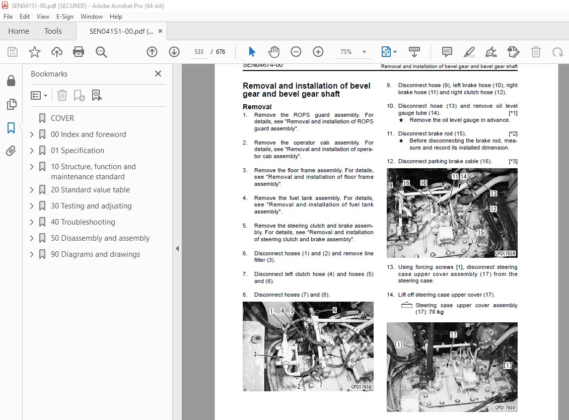
Removal and installation of bevel gear and bevel gear shaft 533
Removal and installation of final drive assembly 540
Disassembly and assembly of final drive assembly 542
400 Undercarriage and frame 556
Removal and installation of track frame assembly 557
Removal and installation of idler assembly 559
Disassembly and assembly of idler assembly 560
Removal and installation of recoil spring assembly 565
Disassembly and assembly of recoil spring assembly 566
Removal and installation of track roller assembly 569
Disassembly and assembly of track roller assembly 570
Removal and installation of carrier roller assembly 574
Disassembly and assembly of carrier roller assembly 575
Check before expanding track shoe assembly 578
Expansion (normal), expansion (internal abnormality) and installation of track shoe assembly 578
Overall disassembly and overall assembly of track shoe assembly 581
Link press-fitting jig dimensions table 597
Field disassembly and assembly of one link 598
Removal and installation of pivot shaft assembly 605
Removal and installation of equalizer bar assembly 607
Removal and installation of equalizer bar side bushing 609
Removal and installation of segment teeth 610
500 Hydraulic system 612
Removal and installation of work equipment valve assembly 613
Disassembly and assembly of work equipment control valve assembly 616
Removal and installation of scavenging pump 617
Removal and installation of power train and lubricating oil pump assembly 618
Removal and installation of work equipment pump assembly 620
Disassembly and assembly of hydraulic cylinder assembly 622
600 Work equipment 628
Removal and installation of blade assembly 629
Removal and installation of ripper assembly 632
700 Cab and its attachments 636
Removal and installation of ROPS guard assembly 637
Removal and installation of operator cab assembly 638
Removal and installation of operator’s cab glass (Stuck glass) 641
Removal and installation of floor frame assembly 649
Removal and installation of heater unit assembly 655
Removal and installation of monitor panel assembly 659
Removal and installation of dashboard assembly 660
90 Diagrams and drawings 664
100 Hydraulic diagrams and drawings 664
Power train hydraulic circuit diagram 666
Steering, work equipment hydraulic circuit diagram 667
200 Electrical diagrams and drawings 670
Electrical circuit diagram 672
Electrical circuit diagram (Inside cab) 673
Connector list and stereogram 674
IMAGES PREVIEW OF THE MANUAL:
S.V 27/12/24



