Komatsu D65EXi-18 D65PXi-18 Bulldozer Shop Manual SEN06716-10 PDF
$41.95
Komatsu D65EXi-18 D65PXi-18 Bulldozer Shop Manual SEN06716-10 – PDF DOWNLOAD
D65PXi-91310 and up
Description
Komatsu D65EXi-18 D65PXi-18 Bulldozer Shop Manual SEN06716-10 – PDF DOWNLOAD
FILE DETAILS:
Komatsu D65EXi-18 D65PXi-18 Bulldozer Shop Manual SEN06716-10 – PDF DOWNLOAD
Language : English
Pages : 3608
Downloadable : Yes
File Type : PDF
IMAGES PREVIEW OF THE MANUAL:
TABLE OF CONTENTS:
Komatsu D65EXi-18 D65PXi-18 Bulldozer Shop Manual SEN06716-10 – PDF DOWNLOAD
D65PXi-91310 and up
Cover 1
00 Index and Foreword 3
Index 4
Abbreviation List 25
Foreword, Safety, Basic Information 31
How to Read the Shop Manual 31
Safety Notice for Operation 33
Precautions to Prevent Fire 41
Procedures If Fire Occurs 43
Precautions When You Discard Waste Materials 44
Procedures for Exhaust Gas Regulations 45
Precautions for DEF 46
General Character and Precautions for Handling 46
Precautions When You Add 46
Precautions for Storage 46
Precautions for Fire Hazard and Leakage 46
Other Precautions 46
Store DEF 47
Precautions When You Handle Hydraulic Equipment 48
Precautions When You Disconnect and Connect Pipings 51
Precautions When You Handle Electrical Equipment 58
Precautions When You Handle Fuel System Equipment 60
Precautions When You Handle Intake System Equipment 61
Practical Use of KOMTRAX 62
Disconnect and Connect Push-Pull Type Coupler 63
How to Disconnect and Connect Type 1 Push-Pull Type Coupler 63
How to Disconnect and Connect Type 2 Push-Pull Type Coupler 64
How to Disconnect and Connect Type 3 Push-Pull Type Coupler 65
Precautions for Disconnection and Connection of Connectors 67
Disconnect and Connect Deutsch Connector 71
How to Disconnect and Connect Slide Lock Type Connector 72
Disconnect and Connect Connector with Lock to Pull 74
Disconnect and Connect Connector with Lock to Push 75
Disconnect and Connect Connector with Housing to Rotate 77
How to Read the Codes for Electric Cable 78
Explanation of Terms for Maintenance Standard 82
Standard Tightening Torque Table 85
Conversion Table 92
01 Specification 97
Table of Contents 98
Abbreviation List 99
Specifications 105
Specification Drawing 105
Specification Drawing: D65EXI-18 105
Specification Drawing: D65PXI-18 107
Specification Drawing: D65PXI-18 (Wide Gauge Specification) 109
Specifications 111
Specifications: D65EXI-18 111
Specifications: D65PXI-18 117
Specifications: D65PXI-18 (Wide Gauge Specification) 123
Weight Table 128
Weight Table: D65EXI-18 128
Weight Table: D65PXI-18 131
Weight Table: D65PXI-18 (Wide Gauge Specification) 134
Table of Fuel, Coolant, and Lubricants 136
10 Structure and Function 139
Table of Contents 140
Abbreviation List 144
Urea SCR System 150
Layout Drawing of Urea SCR System 150
Urea SCR System Diagram 152
Function of Urea SCR System 153
Function of DEF System 153
Inducement Strategy 156
Component Parts of Urea SCR System 170
DEF Mixing Tube 170
SCR Assembly 171
DEF Tank 173
DEF Pump 175
DEF Injector 176
DEF Hose 177
DEF Tank Heating Valve 178
Boot-up System 179
Layout Drawing of Boot-up System (Machine with KOMTRAX Terminal) 179
Layout Drawing of Boot-up System (Machine with Gateway Function Controller) 181
System Operating Lamp System 183
System Diagram of System Operating Lamp System (Machine with KOMTRAX Terminal) 183
System Diagram of System Operating Lamp System (Machine with Gateway Function Controller) 183
Function of System Operating Lamp System (Machine with KOMTRAX Terminal) 183
Function of System Operating Lamp System (Machine with Gateway Function Controller) 184
Battery Disconnect Switch 186
Layout Drawing of Battery Disconnect Switch 186
Function of Battery Disconnect Switch 186
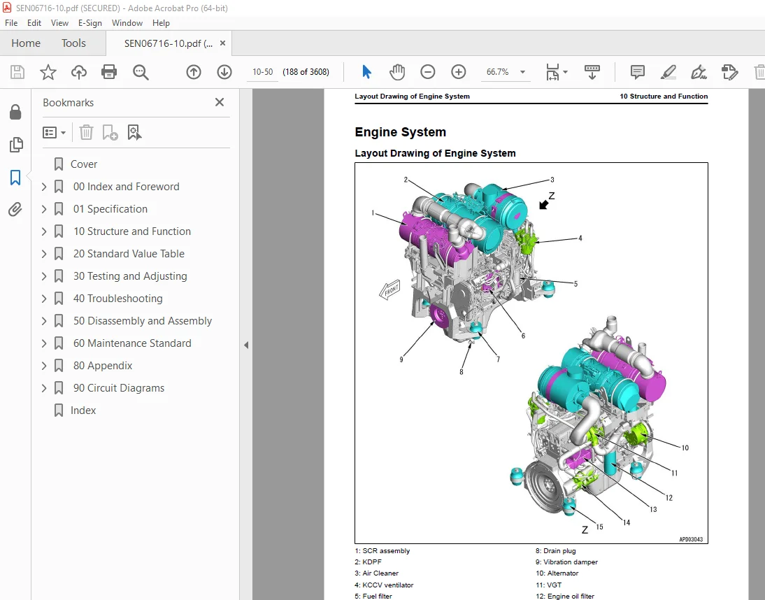
Engine System 188
Layout Drawing of Engine System 188
Engine Control System 190
Layout of Engine Control System (Machine with KOMTRAX Terminal) 190
Layout of Engine Control System (Machine with Gateway Function Controller) 192
System Diagram of Engine Control System (Machine with KOMTRAX Terminal) 193
System Diagram of Engine Control System (Machine with Gateway Function Controller) 195
Function of Engine Control System (Machine with KOMTRAX Terminal) 197
Function of Engine Control System (Machine with Gateway Function Controller) 199
Automatic Idle Stop System 201
Automatic Idle Stop System Diagram (Machine with KOMTRAX Terminal) 201
System Diagram of Automatic Idle Stop System (Machine with Gateway Function Controller) 202
Function of Automatic Idle Stop System 202
Component Parts of Engine System 205
Damper 205
VGT 207
EGR System 211
EGR Valve 213
EGR Cooler 215
KCCV System 217
KCCV Ventilator 219
KDPF 221
Cooling System 225
Layout Drawing of Cooling System 225
Specifications of Cooling System 226
Cooling Fan Control System 227
System Diagram of Cooling Fan Control System 227
Function of Cooling Fan Control System 228
Component Parts of Cooling System 230
Cooling Fan Pump 230
Cooling Fan Motor 239
Hydraulic Oil Cooler Bypass Valve 246
Control System 247
Layout Drawing of Control System (Machine with KOMTRAX Terminal) 247
Layout Drawing of Control System (Machine with Gateway Function Controller) 248
Machine Monitor System 249
System Diagram of Machine Monitor System (Machine with KOMTRAX Terminal) 249
System Diagram of Machine Monitor System (Machine with Gateway Function Controller) 250
Function of Machine Monitor System 250
KOMTRAX System 251
KOMTRAX System Diagram (Machine with KOMTRAX Terminal) 251
System Diagram of KOMTRAX System (Machine with Gateway Function Controller) 251
Function of KOMTRAX System 252
Component Parts of Control System 253
Machine Monitor 253
KOMTRAX Terminal 269
Gateway Function Controller 271
Communication Terminal 274
Power Train Controller 276
Engine Controller 280
Hydraulic System 287
Layout Drawing of Hydraulic System 287
CLSS 288
Structure of CLSS 288
Function of CLSS 289
Component Parts of Hydraulic System 291
Hydraulic Tank 291
Work Equipment and HSS Pump 293
LS Valve 299
PC Valve 304
PC-EPC Valve 309
Control Valve 312
Power Train System 343
Layout Drawing of Power Train System 343
Operation of Power Train System 346
Transmission, Steering, and Brake Control 347
Layout Drawing of Transmission, Steering, and Brake Control System 347
Function of Transmission, Steering, and Brake Control 348
Palm Command Control System 349
Palm Command Control System Diagram 349
HSS System 353
HSS System Diagram 353
Function of HSS System 354
Centralized Pressure Pickup Port 356
Layout Drawing of Centralized Pressure Pickup Port 356
Function of Centralized Pressure Pickup Port 356
Component Parts of Power Train System 357
Universal Joint 357
Power Train Mount 358
Torque Converter and PTO 359
Lockup Clutch ECMV 365
Transmission 368
Transmission Control Valve 380
Forward and Reverse Clutch ECMV and Gear Speed Clutch ECMV 382
Main Relief Valve and Torque Converter Relief Valve 387
Transmission Lubrication Relief Valve 389
Bevel Gear Shaft, HSS, and Brake 390
Brake Valve 409
Final Drive 413
Scavenging Pump 417
Steering Lubrication Pump and Power Train Pump 418
HSS Motor 419
Electric Steering Electric Lever 425
Work Equipment System 428
Work Equipment Control 428
Layout Drawing of Work Equipment Control 428
Function of Work Equipment Control 429
Layout of Tilt Dozer and Power Tilt Pitch Dozer Series 431
Layout of Power Angle Power Tilt Dozer Series 432
Layout Drawing of Fixed Multi-Shank Ripper 433
Component Parts of Work Equipment System 434
Self-Pressure Reducing Valve 434
Work Equipment Lock Solenoid Valve 440
Blade PPC Valve 445
Ripper PPC Valve 451
Blade Pitch Selector Solenoid Valve 454
Pilot Circuit Accumulator 455
Angle Control EPC Valve 456
Quick Drop Valve 459
Piston Valve 461
ICT System 463
Layout Drawing of ICT System 463
System Diagram of ICT Control System 466
Blade Control System 468
Function of Blade Control System 468
Leveling Mode System Diagram 470
Function of Leveling Mode 471
Dozing Mode System Diagram 472
Function of Dozing Mode 473
Operation of Dozing Mode 473
Smooth Start System 474
Smooth Start System Diagram 474
Function of Smooth Start System 474
Operation of Smooth Start System 475
Slip Control System 476
Slip Control System Diagram 476
Function of Slip Control System 477
Operation of Slip Control System 477
Assist Control System 478
Assist Control System Diagram 478
Function of Assist Control System 478
Operation of Assist Control System 479
Component Parts of ICT System 480
ICT Sensor Controller 480
Control Box 487
GNSS Receiver 490
GNSS Antenna 494
IMU Sensor 495
Cylinder EPC Valve Block Assembly 499
Stroke and Reset Sensor for Blade Lift Cylinder 505
Stroke Sensor for Blade Tilt Cylinder 508
Stroke Sensor for Blade Angle Cylinder 510
Undercarriage and Frame 512
Main Frame 512
Structure of Main Frame 512
Suspension 514
Structure of Suspension 514
Specifications of Suspension 515
Function of Suspension 516
Track Frame and Idler Cushion 517
Structure of Track Frame and Idler Cushion 517
Function of Track Frame and Idler Cushion 519
Work Equipment 520
Structure of Front Work Equipment (For Tilt Dozer and Power Tilt Pitch Dozer Series) 520
Structure of Front Work Equipment (For Power Angle Power Tilt Dozer Series) 521
Structure of Fixed Multi-Shank Ripper 522
CAB Related Parts 523
ROPS CAB 523
Structure of ROPS CAB (Machine with KOMTRAX Terminal) 523
Structure of ROPS CAB (Machine with Gateway Function Controller) 524
Function of ROPS CAB 525
CAB Mount 526
Structure of CAB Mount 526
Function of CAB Mount 526
20 Standard Value Table 527
Table of Contents 528
Abbreviation List 529
Standard Value Table for Engine 535
Standard Value Table for Engine: D65EXI-18 535
Standard Value Table for Engine: D65PXI-18 540
Standard Value Table for Machine 545
Standard Value Table for Machine: D65EXI-18 545
Standard Value Table for Machine: D65PXI-18 561
Machine Posture and Procedures to Measure Performance 578
Standard Value Table for Electricity 580
Standard Value Table for Electricity 580
30 Testing and Adjusting 589
Table of Contents 590
Precautions Before Work 594
Abbreviation List 595
Related Information on Testing and Adjusting 601
Tools for Testing and Adjusting 601
Sketch of Tools for Testing and Adjusting 610
Engine and Cooling System 613
Examine Engine Speed 613
How to Examine Engine Speed 613
Examine Boost Pressure 617
How to Examine Boost Pressure 617
Examine Exhaust Gas Temperature 619
How to Examine Exhaust Gas Temperature 619
Examine Exhaust Gas Color 621
How to Examine Exhaust Gas Color with the Handy Smoke Checker 621
How to Examine Exhaust Gas Color with Smoke Meter 621
Examine Mass Air Flow and Temperature Sensor 623
How to Examine Mass Air Flow and Temperature Sensor 623
Examine and Adjust Valve Clearance 625
Check Valve Clearance 625
Adjust Valve Clearance 626
Examine Compression Pressure 628
How to Examine Compression Pressure 628
Examine Blowby Pressure 630
How to Examine Blowby Pressure 630
Examine Engine Oil Pressure 633
How to Examine Engine Oil Pressure 633
Examine EGR Valve and VGT Oil Pressure 634
How to Examine EGR Valve and VGT Oil Pressure 634
Examine Fuel Pressure 636
How to Examine Fuel Pressure 637
Examine Fuel Discharge, Return and Leakage 643
How to Examine Fuel Discharge, Return, and Leakage 644
Bleed Air from Fuel System 648
How to Bleed Air from Fuel System 648
Examine Fuel Circuit for Leakage 650
How to Examine Fuel System for Leakage 650
Handle Cylinder Cut-out Mode Operation 652
Handle No-Injection Cranking Operation 653
Examine and Adjust Air Conditioner Compressor Belt Tension 654
How to Examine Air Conditioner Compressor Belt Tension 654
How to Adjust Air Conditioner Compressor Belt Tension 654
Examine Alternator Belt 655
How to Examine Alternator Belt 655
Examine Automatic Tensioner 657
How to Examine Automatic Tensioner 657
Write Correction for Ash in Soot Accumulation to Engine Controller 659
How to Write Correction for Ash in Soot Accumulation to Engine Controller 659
Examine SCR Related Functions 660
Examine DEF Pump Raised Pressure 664
Examine Injection Volume from DEF Injector 667
Examine DEF Line Heater Relay 1 672
Examine DEF Line Heater Relay 2 675
Examine DEF Pump Heater Relay 678
Examine DEF Tank Heater Valve 681
Examine SCR Denitration Efficiency 684
Clean DEF Tank 687
How to Clean DEF Tank 687
Clean DEF Tank Mounting Part 691
How to Clean DEF Tank Mounting Part 691
Clean DEF Pump 693
How to Clean DEF Pump 693
Adjust Decelerator Pedal 699
How to Adjust Decelerator Pedal 699
Power Train 701
Examine Power Train Oil Pressure 701
How to Examine Power Train Oil Pressure 702
Adjust Transmission Output Shaft Speed Sensor 713
How to Adjust Transmission Output Shaft Speed Sensor 713
Examine Brake Performance Simply 715
How to Examine Brake Performance Simply 715
Adjust Brake Pedal 716
How to Adjust Brake Pedal 716
Adjust Parking Brake Lever 718
How to Adjust Parking Brake Lever 718
Move Machine by Parking Brake Release When Machine Does Not Travel 720
Move Machine with Hydraulic Type Parking Brake Release System 720
Move Machine with Electric Type Parking Brake Release System 721
Undercarriage and Frame 723
Adjust Idler Clearance 723
How to Adjust Idler Clearance 723
Examine and Adjust Track Tension 724
How to Examine Track Tension 724
How to Adjust Track Tension 724
Hydraulic System 725
Release Remained Pressure in Hydraulic Circuit 725
How to Release Remained Pressure in Hydraulic System 725
Examine and Adjust Work Equipment and HSS Oil Pressure 726
How to Examine Work Equipment and HSS Oil Pressure 726
Adjust Oil Pressure of Work Equipment and HSS 730
Examine Oil Pressure of Control Circuit 731
Examine Oil Pressure in Control Circuit 731
Examine PPC Valve Outlet Pressure 733
Examine Outlet Pressure in PPC Valve 733
Bleed Air from HSS Pump 735
How to Bleed Air from HSS Pump 735
Examine and Adjust Play of Work Equipment PPC Valve 736
How to Examine Play of Work Equipment PPC Valve 736
How to Adjust Play of Work Equipment PPC Valve 737
Examine Cooling Fan Speed 738
How to Examine Cooling Fan Speed 738
Examine Cooling Fan Circuit Oil Pressure 739
How to Examine Cooling Fan Circuit Oil Pressure 739
Bleed Air in Cooling Fan Pump 741
How to Bleed Air in Cooling Fan Pump 741
Examine Parts Which Cause Hydraulic Drift of Work Equipment 742
How to Examine Parts Which Cause Hydraulic Drift of Blade Lift Cylinder 742
How to Examine the Parts Which Cause Hydraulic Drift of Blade Tilt Cylinder 742
How to Examine the Parts Which Cause Hydraulic Drift of Ripper Lift Cylinder 743
Examine Oil Leakage from Work Equipment Cylinder 744
How to Examine Internal Oil Leakage of Work Equipment Cylinder 744
Bleed Air from Work Equipment Cylinders 746
Bleed Air from Work Equipment Cylinder 746
Work Equipment 748
Adjust Work Equipment Lock Lever 748
How to Adjust Work Equipment Lock Lever 748
CAB Related Parts 750
Examine and Adjust Operator Cab 750
Examine Operator Cab 750
Adjust Operator Cab 752
Electrical System 755
Set and Operate Machine Monitor 755
Operator Mode 759
Function to Show Technician Identification Status Screen 759
Function to Show Operator Identification Input Screen 759
Examine Function by LCD (Liquid Crystal Display) 760
Examine Function of Service Meter 760
Usage Limitation and Change Maintenance Password 760
Service Mode 763
How to Operate Service Mode 763
How to See Pre-defined Monitoring Information 764
How to Examine Self-Define Monitor Information 777
Abnormality Record Menu 789
How to See Maintenance Record 793
Maintenance Mode Setting 794
Set Phone Number Entry 798
Default Menu 800
Diagnostic Tests Menu 807
Adjustment Menu 816
No-Injection Cranking Operation 881
KOMTRAX Settings Menu 883
Show Service Message 887
Start Up KOMTRAX Terminal (Machine with KOMTRAX Terminal) 889
Stop Use of KOMTRAX Terminal (Machine with KOMTRAX Terminal) 894
Start Up KOMTRAX System (Machine with Gateway Function Controller) 896
Stop Use of KOMTRAX System (Machine with Gateway Function Controller) 902
Adjust When Power Train Controller is Replaced 904
How to Adjust When Power Train Controller is Replaced 904
Adjust Rearview Camera Angle 907
How to Adjust Rearview Camera Angle 907
Handle Voltage Circuit of Engine Controller 908
Handle Battery Disconnect Switch (Machine with KOMTRAX Terminal) 909
Handle Battery Disconnect Switch (Machine with Gateway Function Controller) 910
Examine Diodes 911
Examine Diodes by Digital Tester 911
How to Examine Diodes by Analog Tester 911
ICT System 912
Set and Operate Control Box 912
Examine and Adjust ICT Related Devices (SIGMA Power Tilt Pitch Dozer) 914
Examine and Adjust ICT Related Devices (SIGMADOZER, Semi-U Dozer, Straight Tilt Dozer) 917
Examine and Adjust ICT Related Devices (Power Angle Power Tilt Dozer) 920
Calibrate Blade Edge Position (SIGMA Power Tilt Pitch Dozer) 923
Calibrate Blade Edge Position (SIGMADOZER, Straight Tilt Dozer, Power Angle Power Tilt Dozer) 924
How to Operate Blade Calibration Menu (Pitch Rod Calibration) (SIGMADOZER, Semi-U Dozer, Straight Tilt Dozer) 925
How to Operate Blade Calibration Menu (Pitch Rod Calibration) (Power Angle Power Tilt Dozer) 928
How to Operate Blade Calibration Menu (Machine Cal Step A) (SIGMA Power Tilt Pitch Dozer) 931
How to Operate Blade Calibration Menu (Machine Cal Step A) (SIGMADOZER, Straight Tilt Dozer) 935
How to Operate Blade Calibration Menu (Machine Cal Step A) (Semi-U Dozer) 939
How to Operate Blade Calibration Menu (Machine Cal Step A) (Power Angle Power Tilt Dozer) 944
How to Operate Blade Calibration Menu (Machine Cal Step B) (SIGMA Power Tilt Pitch Dozer) 949
How to Operate Blade Calibration Menu (Machine Cal Step B) (SIGMADOZER, Semi-U Dozer, Straight Tilt Dozer) 964
How to Operate Blade Calibration Menu (Machine Cal Step B) (Power Angle Power Tilt Dozer) 978
Calibrate IMU Sensor 992
How to Calibrate IMU Sensor 992
Reset Cylinder Stroke End (SIGMA Power Tilt Pitch Dozer, SIGMADOZER, Semi-U Dozer Straight Tilt Dozer) 999
Reset Cylinder Stroke End (Power Angle Power Tilt Dozer) 1001
Reset Lift Cylinder Stroke End 1001
Reset Tilt Cylinder Stroke End 1002
Reset Angle Cylinder Stroke End 1002
Set Standard Angle of Blade Edge 1004
How to Input Wear Volume of Blade Edge and Track Shoes 1006
Examine and Adjust Blade Elevation 1007
Examine Blade Elevation (SIGMA Power Tilt Pitch Dozer) (For Old Control Box) 1007
Examine Blade Elevation (SIGMA Power Tilt Pitch Dozer) (For New Control Box) 1010
Examine Blade Elevation (SIGMADOZER, Semi-U Dozer, Straight Tilt Dozer) (For Old Control Box) 1014
Examine Blade Elevation (SIGMADOZER, Semi-U Dozer, Straight Tilt Dozer) (For New Control Box) 1017
Examine Blade Elevation (Power Angle Power Tilt Dozer) (For Old Control Box) 1020
Examine Blade Elevation (Power Angle Power Tilt Dozer) (For New Control Box) 1023
Adjust Blade Elevation (For Old Control Box) 1026
Adjust Blade Elevation (For New Control Box) 1026
Examine Stroke Sensor for Lift Cylinder 1028
How to Examine Stroke Sensor for Lift Cylinder (SIGMA Power Tilt Pitch Dozer, SIGMADOZER, Semi-U Dozer, Straight Tilt Dozer) 1028
How to Examine Stroke Sensor for Lift Cylinder (Power Angle Power Tilt Dozer) 1031
Examine Stroke Sensor for Tilt Cylinder 1033
How to Examine Stroke Sensor for Tilt Cylinder 1033
Examine Stroke Sensor for Angle Cylinder 1035
How to Examine Stroke Sensor for Angle Cylinder 1035
Examine and Adjust Reset Sensor for Lift Cylinder 1037
How to Examine Reset Sensor for Lift Cylinder (SIGMA Power Tilt Pitch Dozer, SIGMADOZER, Semi-U Dozer, Straight Tilt Dozer) 1037
How to Examine Reset Sensor for Lift Cylinder (Power Angle Power Tilt Dozer) 1038
How to Adjust Reset Sensor for Lift Cylinder (SIGMA Power Tilt Pitch Dozer) 1039
How to Adjust Reset Sensor for Lift Cylinder (SIGMADOZER, Semi-U Dozer, Straight Tilt Dozer) 1039
How to Adjust Reset Sensor for Lift Cylinder (Power Angle Power Tilt Dozer) 1039
Adjust When ICT Sensor Controller is Replaced 1040
How to Adjust When ICT Sensor Controller is Replaced (SIGMA Power Tilt Pitch Dozer) 1040
Adjust When ICT Sensor Controller is Replaced (SIGMADOZER, Semi-U Dozer, Straight Tilt Dozer) 1042
How to Adjust When ICT Sensor Controller is Replaced (Power Angle Power Tilt Dozer) 1045
Adjust When ICT Related Devices are Repaired or Replaced (SIGMA Power Tilt Pitch Dozer) 1048
Adjust When ICT Related Devices are Repaired or Replaced (SIGMADOZER, Semi-U Dozer, Straight Tilt Dozer) 1053
Adjust When ICT Related Devices are Repaired or Replaced (Power Angle Power Tilt Dozer) 1058
Pm Clinic 1061
Pm Clinic Service 1061
Pm Clinic Check Sheet: D65EXI-18 1063
Pm Clinic Check Sheet: D65PXI-18 1073
Pm Clinic Check Sheet for Undercarriage: D65EXI-18 1083
Pm Clinic Check Sheet for Undercarriage: D65PXI-18 1086
40 Troubleshooting 1089
Table of Contents 1090
Precautions Before Work 1102
Abbreviation List 1103
Related Information to Troubleshooting 1109
General Troubleshooting Points 1109
Troubleshooting Points for Urea SCR System 1110
Sequence of Events in Troubleshooting 1124
Checks Before Troubleshooting 1126
Inspection Procedure Before Troubleshooting 1128
Walk-Around Check 1128
Test in Accordance with Testing Procedure 1130
How to Examine Electric Equipment 1130
Preparation for Troubleshooting of Electrical System 1138
Procedure for Troubleshooting 1146
Symptom and Troubleshooting Numbers 1149
Information Shown in Troubleshooting Table 1154
Diagnose Open Circuit of Hydraulic Pressure Sensor System Wiring Harness 1156
Connector List and Layout (Machine with KOMTRAX Terminal) 1158
Connector List and Layout (Machine with Gateway Function Controller) 1177
Connector Contact Connection Table 1196
T-Branch Box and T-Branch Adapter Table 1236
Fuse Location Table (Machine with KOMTRAX Terminal) 1242
Fuse Location Table (Machine with Gateway Function Controller) 1245
Precautions When You Clean and Replace KDPF (KCSF and KDOC) 1248
Prepare Short Circuit Electrical Connector (For Failure Codes [CA1883] and [CA3135]) 1252
Failure Code Table 1254
Troubleshooting by Failure Code (Display of Code) 1276
Failure Code [1500L0] 1276
Failure Code [15SAL1] 1277
Failure Code [15SALH] 1279
Failure Code [15SBL1] 1281
Failure Code [15SBLH] 1283
Failure Code [15SEL1] 1285
Failure Code [15SELH] 1287
Failure Code [15SFL1] 1289
Failure Code [15SFLH] 1291
Failure Code [15SGL1] 1293
Failure Code [15SGLH] 1295
Failure Code [15SJL1] 1297
Failure Code [15SJLH] 1299
Failure Code [1800MW] 1301
Failure Code [879AKA] 1302
Failure Code [879AKB] 1303
Failure Code [879BKA] 1304
Failure Code [879BKB] 1306
Failure Code [879CKA] 1308
Failure Code [879CKB] 1309
Failure Code [879DKZ] 1310
Failure Code [879EMC] 1312
Failure Code [879FMC] 1313
Failure Code [879GKX] 1314
Failure Code [989L00] 1316
Failure Code [989M00] 1317
Failure Code [989N00] 1318
Failure Code [A1U0N3] 1319
Failure Code [A1U0N4] 1321
Failure Code [A900FR] 1323
Failure Code [A900N6] 1324
Failure Code [A900NY] 1325
Failure Code [AA10NX] 1326
Failure Code [AB00KE] 1328
Failure Code [AQ10N3] 1330
Failure Code [AS00N3] 1332
Failure Code [AS00R2] 1334
Failure Code [AS00R3] 1335
Failure Code [AS00R4] 1336
Failure Code [AS00R5] 1337
Failure Code [AS00R6] 1338
Failure Code [AS00ZK] 1339
Failure Code [AS10KM] 1340
Failure Code [AS10NR] 1341
Failure Code [AS10NT] 1342
Failure Code [B@BAZG] 1343
Failure Code [B@BCNS] 1344
Failure Code [B@BCQA] 1345
Failure Code [B@BCZK] 1347
Failure Code [B@CENS] 1349
Failure Code [B@HANS] 1350
Failure Code [CA115] 1351
Failure Code [CA122] 1352
Failure Code [CA123] 1354
Failure Code [CA131] 1356
Failure Code [CA132] 1358
Failure Code [CA144] 1361
Failure Code [CA145] 1363
Failure Code [CA153] 1365
Failure Code [CA154] 1368
Failure Code [CA187] 1371
Failure Code [CA221] 1373
Failure Code [CA222] 1375
Failure Code [CA227] 1377
Failure Code [CA234] 1378
Failure Code [CA238] 1379
Failure Code [CA239] 1381
Failure Code [CA249] 1383
Failure Code [CA256] 1385
Failure Code [CA271] 1387
Failure Code [CA272] 1389
Failure Code [CA281] 1391
Failure Code [CA322] 1392
Failure Code [CA323] 1394
Failure Code [CA324] 1396
Failure Code [CA325] 1398
Failure Code [CA331] 1400
Failure Code [CA332] 1402
Failure Code [CA343] 1404
Failure Code [CA351] 1405
Failure Code [CA352] 1406
Failure Code [CA356] 1409
Failure Code [CA357] 1411
Failure Code [CA386] 1413
Failure Code [CA428] 1414
Failure Code [CA429] 1416
Failure Code [CA435] 1418
Failure Code [CA441] 1420
Failure Code [CA442] 1422
Failure Code [CA449] 1423
Failure Code [CA451] 1427
Failure Code [CA452] 1430
Failure Code [CA488] 1432
Failure Code [CA515] 1433
Failure Code [CA516] 1435
Failure Code [CA553] 1437
Failure Code [CA555] 1438
Failure Code [CA556] 1439
Failure Code [CA559] 1440
Failure Code [CA595] 1444
Failure Code [CA687] 1445
Failure Code [CA689] 1447
Failure Code [CA691] 1452
Failure Code [CA692] 1454
Failure Code [CA697] 1456
Failure Code [CA698] 1457
Failure Code [CA731] 1458
Failure Code [CA778] 1460
Failure Code [CA1117] 1465
Failure Code [CA1664] 1466
Failure Code [CA1669] 1469
Failure Code [CA1673] 1470
Failure Code [CA1677] 1471
Failure Code [CA1678] 1472
Failure Code [CA1682] 1473
Failure Code [CA1683] 1478
Failure Code [CA1684] 1480
Failure Code [CA1686] 1482
Failure Code [CA1691] 1483
Failure Code [CA1694] 1486
Failure Code [CA1695] 1489
Failure Code [CA1696] 1490
Failure Code [CA1712] 1492
Failure Code [CA1713] 1495
Failure Code [CA1714] 1497
Failure Code [CA1715] 1498
Failure Code [CA1776] 1499
Failure Code [CA1777] 1502
Failure Code [CA1843] 1505
Failure Code [CA1844] 1507
Failure Code [CA1879] 1510
Failure Code [CA1881] 1513
Failure Code [CA1883] 1516
Failure Code [CA1885] 1520
Failure Code [CA1887] 1522
Failure Code [CA1921] 1524
Failure Code [CA1922] 1527
Failure Code [CA1942] 1532
Failure Code [CA1993] 1533
Failure Code [CA2185] 1536
Failure Code [CA2186] 1538
Failure Code [CA2249] 1540
Failure Code [CA2265] 1541
Failure Code [CA2266] 1543
Failure Code [CA2271] 1545
Failure Code [CA2272] 1548
Failure Code [CA2288] 1551
Failure Code [CA2311] 1552
Failure Code [CA2349] 1553
Failure Code [CA2353] 1556
Failure Code [CA2357] 1558
Failure Code [CA2381] 1559
Failure Code [CA2382] 1562
Failure Code [CA2383] 1565
Failure Code [CA2386] 1568
Failure Code [CA2387] 1570
Troubleshooting Flowchart 1574
Failure Code [CA2555] 1575
Failure Code [CA2556] 1578
Failure Code [CA2637] 1581
Failure Code [CA2639] 1583
Failure Code [CA2771] 1586
Failure Code [CA2777] 1592
Failure Code [CA2976] 1595
Failure Code [CA3133] 1597
Failure Code [CA3134] 1599
Failure Code [CA3135] 1601
Failure Code [CA3142] 1605
Failure Code [CA3143] 1606
Failure Code [CA3144] 1607
Failure Code [CA3146] 1609
Failure Code [CA3147] 1610
Failure Code [CA3148] 1611
Failure Code [CA3151] 1613
Failure Code [CA3165] 1619
Failure Code [CA3229] 1621
Failure Code [CA3231] 1623
Failure Code [CA3232] 1625
Failure Code [CA3235] 1629
Failure Code [CA3239] 1631
Failure Code [CA3241] 1634
Failure Code [CA3242] 1637
Failure Code [CA3251] 1640
Failure Code [CA3253] 1642
Failure Code [CA3254] 1645
Failure Code [CA3255] 1648
Failure Code [CA3256] 1651
Failure Code [CA3311] 1653
Failure Code [CA3312] 1655
Failure Code [CA3313] 1658
Failure Code [CA3314] 1659
Failure Code [CA3315] 1660
Failure Code [CA3316] 1663
Failure Code [CA3317] 1664
Failure Code [CA3318] 1665
Failure Code [CA3319] 1668
Failure Code [CA3321] 1669
Failure Code [CA3322] 1671
Failure Code [CA3419] 1674
Failure Code [CA3421] 1676
Failure Code [CA3497] 1678
Failure Code [CA3498] 1679
Failure Code [CA3543] 1680
Failure Code [CA3545] 1687
Failure Code [CA3547] 1689
Failure Code [CA3558] 1690
Failure Code [CA3559] 1692
Failure Code [CA3562] 1694
Failure Code [CA3563] 1696
Failure Code [CA3567] 1699
Failure Code [CA3568] 1702
Failure Code [CA3571] 1708
Failure Code [CA3572] 1710
Failure Code [CA3574] 1712
Failure Code [CA3575] 1715
Failure Code [CA3577] 1717
Failure Code [CA3578] 1719
Failure Code [CA3582] 1721
Failure Code [CA3583] 1730
Failure Code [CA3596] 1732
Failure Code [CA3649] 1735
Failure Code [CA3681] 1737
Failure Code [CA3682] 1739
Failure Code [CA3713] 1742
Failure Code [CA3717] 1745
Failure Code [CA3718] 1746
Failure Code [CA3725] 1747
Failure Code [CA3741] 1750
Failure Code [CA3748] 1751
Failure Code [CA3751] 1754
Failure Code [CA3755] 1756
Failure Code [CA3866] 1758
Failure Code [CA3867] 1762
Failure Code [CA3868] 1765
Failure Code [CA3899] 1769
Failure Code [CA3911] 1771
Failure Code [CA3912] 1775
Failure Code [CA3932] 1777
Failure Code [CA3933] 1779
Failure Code [CA3934] 1781
Failure Code [CA3935] 1784
Failure Code [CA3936] 1786
Failure Code [CA4151] 1788
Failure Code [CA4152] 1792
Failure Code [CA4155] 1796
Failure Code [CA4156] 1799
Failure Code [CA4157] 1802
Failure Code [CA4158] 1804
Failure Code [CA4159] 1805
Failure Code [CA4161] 1806
Failure Code [CA4162] 1809
Failure Code [CA4163] 1812
Failure Code [CA4164] 1814
Failure Code [CA4165] 1816
Failure Code [CA4166] 1818
Failure Code [CA4168] 1820
Failure Code [CA4169] 1823
Failure Code [CA4171] 1825
Failure Code [CA4249] 1828
Failure Code [CA4251] 1830
Failure Code [CA4259] 1832
Failure Code [CA4261] 1835
Failure Code [CA4277] 1838
Failure Code [CA4281] 1842
Failure Code [CA4459] 1846
Failure Code [CA4461] 1849
Failure Code [CA4658] 1852
Failure Code [CA4731] 1856
Failure Code [CA4732] 1857
Failure Code [CA4739] 1858
Failure Code [CA4768] 1859
Failure Code [CA4769] 1861
Failure Code [CA4842] 1864
Failure Code [CA4952] (Machine with KOMTRAX Terminal) 1868
Failure Code [CA4952] (Machine with Gateway Function Controller) 1870
Failure Code [CA5115] 1872
Failure Code [CA5383] 1875
Failure Code [D130KA] 1877
Failure Code [D130KB] 1880
Failure Code [D19DKA] 1882
Failure Code [D19DKB] 1884
Failure Code [D19JKZ] 1886
Failure Code [D811MC] (Machine with KOMTRAX Terminal) 1889
Failure Code [D811MC] (Machine with Gateway Function Controller) 1890
Failure Code [D862KA] (Machine with KOMTRAX Terminal) 1891
Failure Code [D862KA] (Machine with Gateway Function Controller) 1892
Failure Code [D8ALKA] (Machine with KOMTRAX Terminal) 1893
Failure Code [D8ALKA] (Machine with Gateway Function Controller) 1895
Failure Code [D8ALKB] (Machine with KOMTRAX Terminal) 1897
Failure Code [D8ALKB] (Machine with Gateway Function Controller) 1899
Failure Code [D8AQKR] (Machine with KOMTRAX Terminal) 1901
Failure Code [D8AQKR] (Machine with Gateway Function Controller) 1903
Failure Code [D8G1KT] 1905
Failure Code [D8G6KT] 1906
Failure Code [DAF0MB] 1907
Failure Code [DAF0MC] 1908
Failure Code [DAF8KB] 1909
Failure Code [DAF9KQ] 1910
Failure Code [DAFGMC] (Machine with KOMTRAX Terminal) 1911
Failure Code [DAFGMC] (Machine with Gateway Function Controller) 1912
Failure Code [DAFLKA] (Machine with KOMTRAX Terminal) 1913
Failure Code [DAFLKA] (Machine with Gateway Function Controller) 1915
Failure Code [DAFLKB] (Machine with KOMTRAX Terminal) 1917
Failure Code [DAFLKB] (Machine with Gateway Function Controller) 1919
Failure Code [DAFQKR] (Machine with KOMTRAX Terminal) 1921
Failure Code [DAFQKR] (Machine with Gateway Function Controller) 1922
Failure Code [DAQW00] 1923
Failure Code [DAZ9KQ] 1924
Failure Code [DAZQKR] 1925
Failure Code [DB2QKR] (Machine with KOMTRAX Terminal) 1926
Failure Code [DB2QKR] (Machine with Gateway Function Controller) 1931
Failure Code [DB2RKR] 1936
Failure Code [DBE0KT] 1942
Failure Code [DBE1KK] 1943
Failure Code [DBE2KK] 1946
Failure Code [DBE5KK] 1949
Failure Code [DBE6KK] 1951
Failure Code [DBE7KK] 1953
Failure Code [DBE9KQ] 1955
Failure Code [DBELKA] 1956
Failure Code [DBELKB] 1958
Failure Code [DBEQKR] 1960
Failure Code [DBERKR] 1961
Failure Code [DBR0KT] 1963
Failure Code [DBR0MC] 1964
Failure Code [DBR1KK] 1965
Failure Code [DBR2KK] 1968
Failure Code [DBR5KK] 1971
Failure Code [DBR7KK] 1973
Failure Code [DBRLKA] (Machine with KOMTRAX Terminal) 1975
Failure Code [DBRLKA] (Machine with Gateway Function Controller) 1977
Failure Code [DBRLKB] (Machine with KOMTRAX Terminal) 1979
Failure Code [DBRLKB] (Machine with Gateway Function Controller) 1981
Failure Code [DBRPMA] 1983
Failure Code [DBRQKR] 1984
Failure Code [DBRRKR] 1986
Failure Code [DBTSKR] 1987
Failure Code [DBUTKA] 1990
Failure Code [DD12KA] 1991
Failure Code [DD12KB] 1993
Failure Code [DD13KA] 1995
Failure Code [DD13KB] 1997
Failure Code [DD14KA] 1999
Failure Code [DD14KB] 2001
Failure Code [DDKFL4] 2003
Failure Code [DDKGL4] 2005
Failure Code [DDKHKA] 2007
Failure Code [DDKHKB] 2009
Failure Code [DDKQKA] 2011
Failure Code [DDKQKB] 2013
Failure Code [DDKRKA] 2015
Failure Code [DDKRKB] 2017
Failure Code [DDKSKA] 2019
Failure Code [DDKSKB] 2021
Failure Code [DDN7KA] 2023
Failure Code [DDN7KB] 2025
Failure Code [DDNLKA] 2027
Failure Code [DDNLKB] 2029
Failure Code [DGS1KA] 2031
Failure Code [DGS1KX] 2033
Failure Code [DGT1KA] 2035
Failure Code [DGT1KX] 2038
Failure Code [DH21KA] 2040
Failure Code [DH21KY] 2042
Failure Code [DHA4KA] 2044
Failure Code [DHAAMA] 2046
Failure Code [DHACMA] 2048
Failure Code [DHSKKA] 2050
Failure Code [DHSKKY] 2052
Failure Code [DHSLKA] 2054
Failure Code [DHSLKY] 2056
Failure Code [DHSWKA] 2058
Failure Code [DHSWKY] 2060
Failure Code [DHSXKA] 2062
Failure Code [DHSXKY] 2064
Failure Code [DHTDKA] 2066
Failure Code [DHTDKY] 2068
Failure Code [DK10KA] 2070
Failure Code [DK10KB] 2073
Failure Code [DK30KA] 2075
Failure Code [DK30KX] 2078
Failure Code [DK30KY] 2079
Failure Code [DK30KZ] 2081
Failure Code [DK30L8] 2082
Failure Code [DK31KA] 2083
Failure Code [DK31KY] 2086
Failure Code [DK40KA] 2088
Failure Code [DK40KY] 2090
Failure Code [DK55KX] 2092
Failure Code [DK55KZ] 2093
Failure Code [DK55L8] 2094
Failure Code [DK56KA] 2095
Failure Code [DK56KY] 2097
Failure Code [DK57KA] 2099
Failure Code [DK57KY] 2101
Failure Code [DK80KA] 2103
Failure Code [DKH1KA] 2106
Failure Code [DKH1KY] 2109
Failure Code [DKS0L8] 2111
Failure Code [DKS1KA] 2112
Failure Code [DKS1KB] 2114
Failure Code [DKS2KA] 2116
Failure Code [DKS2KB] 2118
Failure Code [DKS3KA] 2120
Failure Code [DKS3KB] 2122
Failure Code [DKS3MB] 2124
Failure Code [DKS4L8] 2126
Failure Code [DKS5KA] 2127
Failure Code [DKS5KB] 2129
Failure Code [DKS6KA] 2131
Failure Code [DKS6KB] 2133
Failure Code [DKS7MB] 2135
Failure Code [DKSCL8] 2136
Failure Code [DKSDKA] 2137
Failure Code [DKSDKB] 2139
Failure Code [DKSEKA] 2141
Failure Code [DKSEKB] 2143
Failure Code [DKSFMB] 2145
Failure Code [DKSGL8] 2146
Failure Code [DKSHKA] 2147
Failure Code [DKSHKB] 2149
Failure Code [DKSJKA] 2151
Failure Code [DKSJKB] 2153
Failure Code [DKSKKA] 2155
Failure Code [DKSKKB] 2157
Failure Code [DKSKMB] 2159
Failure Code [DKSLL8] 2161
Failure Code [DKSMKA] 2162
Failure Code [DKSMKB] 2164
Failure Code [DKSNKA] 2166
Failure Code [DKSNKB] 2168
Failure Code [DKSPKA] 2170
Failure Code [DKSPKB] 2172
Failure Code [DKSPMB] 2174
Failure Code [DLM3KA] 2176
Failure Code [DLM3MB] 2178
Failure Code [DLT3KA] 2179
Failure Code [DLT3KB] 2181
Failure Code [DR21KX] 2183
Failure Code [DR31KX] 2184
Failure Code [DUMCKB] 2185
Failure Code [DUMCKY] 2187
Failure Code [DV20KB] 2189
Failure Code [DW5AKA] 2191
Failure Code [DW5AKB] 2193
Failure Code [DW5AKY] 2195
Failure Code [DW7BKA] 2197
Failure Code [DW7BKB] 2199
Failure Code [DW7BKY] 2201
Failure Code [DWN1KA] 2202
Failure Code [DWN1KB] 2204
Failure Code [DWN1KY] 2206
Failure Code [DWN2KA] 2208
Failure Code [DWN2KB] 2210
Failure Code [DWN2KY] 2212
Failure Code [DWN5KA] 2213
Failure Code [DWN5KB] 2215
Failure Code [DWN5KY] 2216
Failure Code [DXA2KA] 2218
Failure Code [DXA2KB] 2220
Failure Code [DXA2KY] 2222
Failure Code [DXH1KA] 2223
Failure Code [DXH1KB] 2225
Failure Code [DXH1KY] 2227
Failure Code [DXH4KA] 2229
Failure Code [DXH4KB] 2231
Failure Code [DXH4KY] 2233
Failure Code [DXH5KA] 2235
Failure Code [DXH5KB] 2237
Failure Code [DXH5KY] 2239
Failure Code [DXH6KA] 2241
Failure Code [DXH6KB] 2243
Failure Code [DXH6KY] 2245
Failure Code [DXH7KA] 2247
Failure Code [DXH7KB] 2249
Failure Code [DXH7KY] 2251
Failure Code [DXH8KA] 2253
Failure Code [DXH8KB] 2255
Failure Code [DXH8KY] 2257
Failure Code [DXHRKA] 2259
Failure Code [DXHRKB] 2261
Failure Code [DXHRKY] 2262
Failure Code [DXHSKA] 2264
Failure Code [DXHSKB] 2266
Failure Code [DXHSKY] 2267
Failure Code [DXHTKA] 2269
Failure Code [DXHTKB] 2271
Failure Code [DXHTKY] 2272
Failure Code [DXHUKA] 2273
Failure Code [DXHUKB] 2275
Failure Code [DXHUKY] 2276
Failure Code [DXJ4KA] 2277
Failure Code [DXJ4KB] 2279
Failure Code [DXJCKA] 2281
Failure Code [DXJCKB] 2283
Failure Code [DXJCKY] 2285
Failure Code [DXJDKA] 2287
Failure Code [DXJDKB] 2289
Failure Code [DXJDKY] 2291
Failure Code [F313KA] 2293
Failure Code [F313KB] 2294
Failure Code [F318KB] 2295
Failure Code [F318KY] 2296
Troubleshooting of Electrical System (E-Mode) 2297
Engine Does Not Start (Engine Does Not Crank) 2297
Manual Preheating System Does Not Operate 2304
Automatic Preheating System Does Not Operate 2307
While Preheating is in Operation, Preheating Monitor Does Not Come On 2309
When Starting Switch is Turned to ON Position, Machine Monitor Shows Nothing 2311
When Starting Switch is Turned to ON Position (with Engine Stopped), Basic Check Monitor Comes On 2315
Air Cleaner Clogging Monitor Comes On in Yellow While Engine is in Operation 2316
Charge Level Monitor Comes On in Red While Engine is in Operation 2317
Engine Coolant Temperature Monitor Comes On in Red While Engine is in Operation 2319
Engine Oil Pressure Monitor Comes On in Red While Engine is in Operation 2320
Power Train Oil Temperature Monitor Comes On in Red While Engine Runs 2321
Hydraulic Oil Temperature Monitor Comes On in Red While Engine is in Operation 2322
Engine Coolant Temperature Gauge Does Not Show Correct Temperature 2323
DEF Level is Not Shown Correctly 2324
Fuel Gauge Does Not Show Normally 2327
Power Train Oil Temperature Gauge Does Not Show Correct Temperature 2329
Hydraulic Oil Temperature Gauge Does Not Show Correct Temperature 2330
Operation Mode Does Not Change 2331
Gear Shift Mode Does Not Change 2332
When You Operate Customize Switch Does Not Show Customize Screen 2333
When You Change Setting on Customize Screen, Setting of Machine is Not Changed 2334
Some Areas of Machine Monitor Screen are Not Shown 2335
REVERSE Slow Mode Function Does Not Operate Correctly 2336
Alarm Buzzer Does Not Operate or Does Not Stop Operation 2337
Service Meter is Not Shown While Starting Switch is in OFF Position 2338
Service Mode Cannot be Selected 2339
Horn Does Not Sound 2340
Horn Does Not Stop 2342
Backup Alarm Does Not Sound 2343
Backup Alarm Does Not Stop Operation 2345
Headlamp Does Not Come On 2346
Rear Lamp Does Not Come On 2350
No Wiper Operates 2353
Front Wiper Does Not Operate 2357
Rear Wiper Does Not Operate 2360
Left Door Wiper Does Not Operate 2363
Right Door Wiper Does Not Operate 2366
Front Washer Does Not Operate 2369
Rear Washer Does Not Operate 2371
Left Door Washer Does Not Operate 2373
Right Door Washer Does Not Operate 2375
KOMTRAX System Does Not Operate Correctly 2377
Control Box Shuts Down After It Shows Messages [GPS receiver not connected!] and [Slope sensor not connected!] 2378
Control Box Shows Messages [GPS receiver not connected !] and [Slope sensor not connected !] 2382
Control Box Shows Message [Waiting for radio link ] 2385
Control Box Shows Message [IMU sensor not connected] Show Production 2386
Control Box Shows Message [Waiting for satellites ] 2387
Control Box Shows Message [GPS receiver not connected!] Show Production 2388
Control Box Shows Message [Cylinder Stroke Reading Abnormal] 2390
Control Box Shows Message [Komatsu CAN Comms Abnormal] 2391
Control Box Shows Message [Komatsu Machine Trouble] 2392
Control Box Shows Message [Waiting to initialize ] 2393
Control Box Shows Message [System initializing] 2394
Control Box Shows Message [Initializing ] 2395
Control Box Shows Message [Configuring GPS] 2396
Control Box Shows Message [No GPS Localization ] 2397
Control Box Shows Message [Low precisions ] 2398
Control Box Shows Message [Heading Initializing] 2399
Control Box Displays [Out of design area ] 2400
Control Box Can Not be Turned on 2401
Control Box Does Not Display Intelligent Machine Control Screen 2402
Control Box Does Not Display Bulldozer Image 2403
Control Box Does Not Display Design Surface 2404
Control Box Touch Panel Does Not Respond 2405
Control Box Touch Panel is Inaccurate 2406
Cylinder Stroke Reset Indication Does Not Go Out 2407
AUTO is Not Shown When AUTO/Manual Switch is Pushed (AUTO Indication Goes off) 2408
Blade Automatic Lower Control Does Not Start While AUTO is Shown 2409
Blade Automatic Raise Control Does Not Start While AUTO is Shown 2410
Blade Automatic Control Function is Not Activated While AUTO is Shown (Blade Automatic Control Stops) 2411
When You Examine and Adjust the Blade Elevation, the Value is Different from Actual Machine 2412
Finished Surface is Inaccurate (The Average Height of Finished Surface is Lower Than Designed Surface or Blade Does Not Touch the Surface) 2413
Finished Surface is Inaccurate (The Finished Surface is Not Smooth) 2414
Finished Surface is Inaccurate (When You Finish Slope Horizontally, Steps are Made in Each Direction) 2415
Machine Cannot Escape from Shoes Slip While Blade Automatic Control is Activated (Shoes Frequently Slips) 2417
Machine Speed Does Not Increase While Blade Automatic Control is Activated 2418
Blade Tilt Angle Does Not Align with Design Surface 2419
Blade Tilts While Blade Automatic Control is Activated 2421
Troubleshooting for Hydraulic and Mechanical Systems (H Mode) 2423
Information Shown in Troubleshooting Table (H-Mode) 2423
System Chart of Hydraulic and Mechanical Systems 2424
Failure Mode and Cause Table 2426
Machine Lacks Power (Drawbar Pull is Not Sufficient) 2434
Machine Does Not Travel (at 2nd or 3rd Gear Speed) 2436
Machine Does Not Move Off at All Gear Speeds 2437
Machine Travels Only in One Direction, Forward or in Reverse 2439
Large Time Lag is in Gear Shifting or Directional Change 2440
Brake Does Not Work 2442
Power Train Oil Overheats 2443
Unusual Noise is Heard from Around Work Equipment and HSS Pump or HSS Motor 2445
Torque Converter Lockup Clutch Does Not Engage 2446
Machine Cannot be Steered (Machine Does Not Turn Left or Right) 2447
Steering Speed or Power is Not Sufficient 2448
All Work Equipment Operate Slowly 2449
All Work Equipment Do Not Operate 2450
Blade Lift Speed or Power is Low 2451
Blade Tilt Speed or Power is Low 2452
Blade Angle Speed or Power is Low 2453
Ripper Lift Speed or Power is Low 2454
Hydraulic Drift of Blade Lift is Large 2455
Hydraulic Drift of Tilted Blade is Large 2456
Hydraulic Drift of Lifted Ripper is Large 2457
Fan Speed is Abnormal (Too High or Low, or Does Not Rotate) 2458
Unusual Noise is Heard from Around Fan 2460
Troubleshooting of Engine (S-Mode) 2461
Information Shown in Troubleshooting Table (S-Mode) 2461
Engine Does Not Crank When Starting Switch is Turned to Start Position 2462
Engine Cranks but No Exhaust Smoke Comes Out 2463
Fuel is Sprayed but Engine Does Not Start (Misfiring: Engine Cranks but Does Not Start) 2464
Engine Startability is Unsatisfactory 2466
Engine Does Not Pick Up Smoothly 2468
Engine Stops During Operation 2470
Engine Does Not Rotate Smoothly 2472
Engine Lacks Output (or Lacks Power) 2473
KDPF Becomes Clogged in a Short Time 2475
Engine Oil Consumption is Excessive 2477
Engine Oil Becomes Dirty Quickly 2478
Fuel Consumption is Excessive 2479
Oil is in Coolant (or Coolant Spurts Back or Coolant Level Goes Down) 2480
Engine Oil Pressure Drops 2481
Fuel Mixes Into Engine Oil 2483
Water Mixes Into Engine Oil (Milky) 2484
Coolant Temperature Increases Too High (Overheat) 2485
Unusual Noise is Heard 2486
Vibration is Excessive 2487
Air Cannot be Bled from Fuel Circuit 2488
Active Regeneration is Done Frequently 2489
Active Regeneration Continues Long 2491
White Smoke is Exhausted During Active Regeneration 2492
DEF Consumption is Excessive 2493
There is an Unusual Smell (Irritating Odor) 2495
Foreign Materials Enter DEF (DEF Increases) 2496
50 Disassembly and Assembly 2497
Table of Contents 2498
Precautions Before Work 2504
Abbreviation List 2505
Related Information on Disassembly and Assembly 2511
How to Read This Manual 2511
Coating Materials List 2512
Special Tool List 2517
Sketches of Special Tools 2540
Engine and Cooling System 2561
Remove and Install Supply Pump Assembly 2561
Remove Supply Pump Assembly 2561
Install Supply Pump Assembly 2565
Remove and Install Injector Assembly 2570
How to Remove Injector Assembly 2571
How to Install Injector Assembly 2578
Remove and Install Cylinder Head Assembly 2589
How to Remove Cylinder Head Assembly 2590
How to Install Cylinder Head Assembly 2600
Remove and Install EGR Valve Assembly 2616
Remove EGR Valve Assembly 2616
Install EGR Valve Assembly 2617
Remove and Install EGR Cooler Assembly 2618
How to Remove EGR Cooler Assembly 2618
How to Install EGR Cooler Assembly 2619
Remove and Install Starter Assembly 2621
Remove Starting Motor Assembly 2621
Install Starting Motor Assembly 2623
Remove and Install Alternator Belt 2626
Remove Alternator Belt 2626
Install Alternator Belt 2627
Remove and Install Automatic Tensioner 2629
Remove Automatic Tensioner 2629
Install Automatic Tensioner 2629
Remove and Install Expansion Tank Assembly 2630
How to Remove Expansion Tank Assembly 2630
How to Install Expansion Tank Assembly 2636
Remove and Install Radiator Assembly 2643
How to Remove Radiator Assembly 2643
How to Install Radiator Assembly 2646
Remove and Install Hydraulic Oil Cooler Assembly 2650
How to Remove Hydraulic Oil Cooler Assembly 2650
How to Install Hydraulic Oil Cooler Assembly 2652
Remove and Install Aftercooler Assembly 2656
Remove Aftercooler Assembly 2656
Install Aftercooler Assembly 2658
Remove and Install Power Train Oil Cooler Assembly 2661
How to Remove Power Train Oil Cooler Assembly 2661
How to Install Power Train Oil Cooler Assembly 2663
Remove and Install Cooling Fan Drive Assembly 2666
Remove Cooling Fan Drive Assembly 2666
Install Cooling Fan Drive Assembly 2667
Remove and Install Cooling Fan Motor Assembly 2670
Remove Cooling Fan Motor Assembly 2670
Install Cooling Fan Motor Assembly 2672
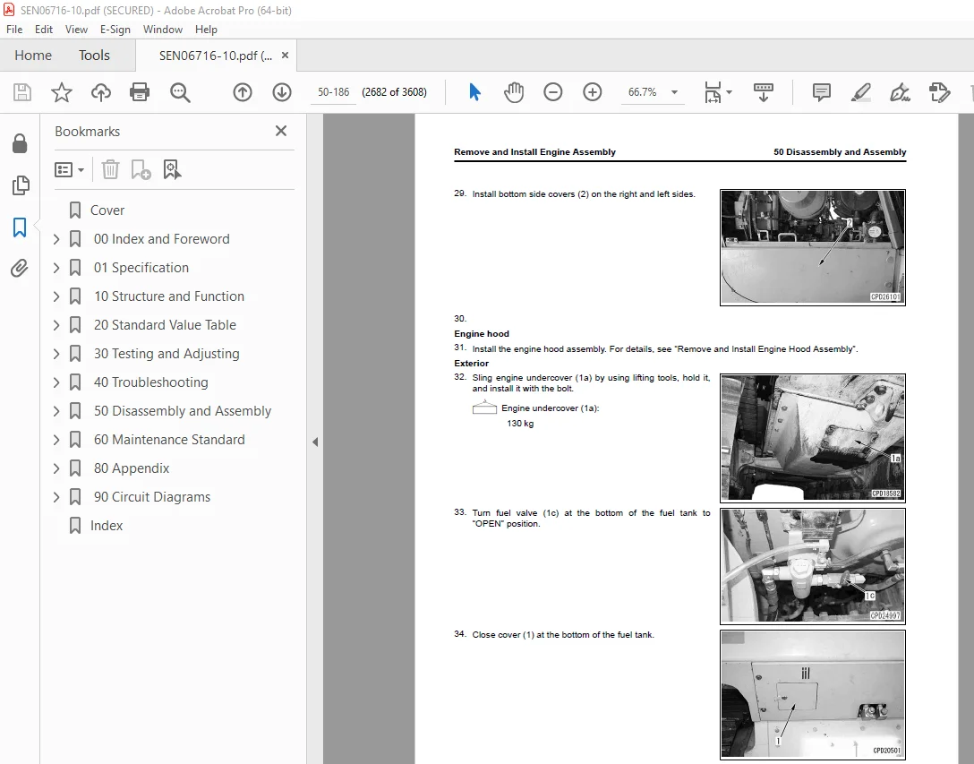
Remove and Install Engine Assembly 2674
Remove Engine Assembly 2674
Install Engine Assembly 2678
Remove and Install Engine Front Oil Seal 2684
How to Remove Engine Front Oil Seal 2684
How to Install Engine Front Oil Seal 2686
Remove and Install Engine Rear Oil Seal 2690
How to Remove Engine Rear Oil Seal 2690
How to Install Engine Rear Oil Seal 2694
Remove and Install Engine Hood Assembly 2702
How to Remove Engine Hood Assembly 2702
How to Install Engine Hood Assembly 2708
Remove and Install Fuel Tank Assembly 2714
Remove Fuel Tank Assembly 2714
Install Fuel Tank Assembly 2717
Remove and Install DEF Tank Assembly 2720
How to Remove DEF Tank Assembly 2721
How to Install DEF Tank Assembly 2725
Remove and Install DEF Tank Sensor Flange Assembly 2729
How to Remove DEF Tank Sensor Flange Assembly 2730
How to Install DEF Tank Sensor Flange Assembly 2734
Remove and Install DEF Tank Sensor 2741
Remove DEF Tank Sensor 2741
Install DEF Tank Sensor 2742
Remove and Install DEF Tank Strainer 2749
Remove DEF Tank Strainer 2749
Install DEF Tank Strainer 2749
Remove and Install KDPF Assembly 2750
How to Remove KDPF Assembly 2750
How to Install KDPF Assembly 2754
Disassemble and Assemble KDPF Assembly 2758
Disassemble KDPF Assembly 2758
Assemble KDPF Assembly 2762
Remove and Install SCR Assembly 2768
How to Remove SCR Assembly 2768
How to Install SCR Assembly 2770
Remove and Install KDPF and SCR Assembly 2773
How to Remove KDPF and SCR Assembly 2773
Install KDPF and SCR Assembly 2780
Remove and Install KCCV Assembly 2787
Remove KCCV Assembly 2787
Install KCCV Assembly 2789
Remove and Install DEF Mixing Tube 2791
Remove DEF Mixing Tube 2791
Install DEF Mixing Tube 2794
Remove and Install DEF Injector 2799
Remove DEF Injector 2799
Install DEF Injector 2802
Remove and Install DEF Pump 2806
Remove DEF Pump 2806
Install DEF Pump 2809
Remove and Install DEF Hose 2812
Remove DEF Hose 2812
Install DEF Hose 2817
Remove and Install Air Cleaner Assembly 2822
Remove Air Cleaner Assembly 2822
Install Air Cleaner Assembly 2823
Remove and Install Air Conditioner Compressor Assembly 2825
Remove Air Conditioner Compressor Assembly 2825
How to Install Air Conditioner Compressor Assembly 2827
Remove and Install Air Conditioner Condenser Assembly 2830
How to Remove Air Conditioner Condenser Assembly 2830
How to Install Air Conditioner Condenser Assembly 2832
Power Train 2834
Remove and Install Damper Assembly 2834
How to Remove Damper Assembly 2834
How to Install Damper Assembly 2837
Remove and Install Power Train Unit Assembly 2842
Remove Power Train Unit Assembly 2842
How to Install Power Train Unit Assembly 2847
Disconnect and Connect Power Train Unit Assembly 2853
How to Disconnect Power Train Unit Assembly 2853
Connect Power Train Unit Assembly 2858
Disassemble and Assemble PTO Assembly 2864
Disassemble PTO Assembly 2864
Assemble PTO Assembly 2867
Disassemble and Assemble Torque Converter Assembly 2871
Disassemble Torque Converter Assembly 2872
Assemble Torque Converter Assembly 2878
Disassemble and Assemble Transmission Assembly 2887
Disassemble Transmission Assembly 2888
Assemble Transmission Assembly 2906
Disassemble and Assemble HSS Assembly 2919
Disassemble HSS Assembly 2921
Assemble HSS Assembly 2932
Remove and Install HSS Motor Assembly 2949
Remove HSS Motor Assembly 2949
How to Install HSS Motor Assembly 2951
Remove and Install Final Drive Assembly 2954
Remove Final Drive Assembly 2954
Install Final Drive Assembly 2957
Disassemble and Assemble Final Drive Assembly 2960
Disassemble Final Drive Assembly 2961
Assemble Final Drive Assembly 2966
Undercarriage and Frame 2974
Remove and Install Track Frame Assembly 2974
Remove Track Frame Assembly 2974
Install Track Frame Assembly 2976
Remove and Install Idler Assembly 2979
Remove Idler Assembly 2979
Install Idler Assembly 2980
Disassemble and Assemble Idler Assembly 2982
Disassemble Idler Assembly 2982
Assemble Idler Assembly 2984
Remove and Install Recoil Spring Assembly 2988
Remove Recoil Spring Assembly 2988
Install Recoil Spring Assembly 2988
Disassemble and Assemble Recoil Spring Assembly 2990
Disassemble Recoil Spring Assembly 2990
Assemble Recoil Spring Assembly 2993
Remove and Install Track Roller Assembly 2996
Remove Track Roller Assembly 2996
Install Track Roller Assembly 2997
Disassemble and Assemble Track Roller Assembly 2998
Disassemble Track Roller Assembly 2998
Assemble Track Roller Assembly 3000
Remove and Install Carrier Roller Assembly 3003
Remove Carrier Roller Assembly 3003
Install Carrier Roller Assembly 3004
Disassemble and Assemble Carrier Roller Assembly 3005
Disassemble Carrier Roller Assembly 3005
Assemble Carrier Roller Assembly 3006
Remove and Install Pivot Shaft Assembly 3009
Remove Pivot Shaft Assembly 3009
Install Pivot Shaft Assembly 3010
Separate and Connect Track Assembly 3011
Examine Before Separation of Track Assembly 3011
Separate Track Assembly (Standard) 3011
How to Separate Track Assembly (When Track Frame Has Internal Defect) 3012
Install Track Assembly 3013
Separate and Connect PLUS Type Track Assembly 3016
Separate PLUS Type Track Assembly Generally 3016
Install PLUS Type Track Assembly 3016
Disassemble and Assemble Track Assembly Generally 3017
How to Disassemble Full Track Shoes Assembly 3017
How to Assemble Full Track Shoes Assembly 3020
Disassemble and Assemble PLUS Type Track Assembly Generally 3032
Disassemble PLUS Type Track Assembly Generally 3033
How to Assemble PLUS Type Track Shoes Assembly Generally 3034
Disassemble and Assemble One Track Link Assembly in Field (Track Assembly) 3049
Disassemble One Track Link Assembly in Field (Track Assembly) 3050
Assemble One Track Link Assembly in Field (Track Assembly) 3051
Disassemble and Assemble One Track Link Assembly in Field (PLUS Type Track Assembly) 3058
Disassemble One Track Link Assembly in Field (PLUS Type Track Assembly) 3059
Assemble One Track Link Assembly in Field (PLUS Type Track Assembly) 3061
Remove and Install Equalizer Bar Assembly 3065
Remove Equalizer Bar Assembly 3065
Install Equalizer Bar Assembly 3066
Disassemble and Assemble Equalizer Bar Bushing 3068
Disassemble Equalizer Bar Bushing 3068
Assemble Equalizer Bar Bushing 3068
Hydraulic System 3070
Remove and Install Hydraulic Tank Assembly 3070
Remove Hydraulic Tank Assembly 3070
How to Install Hydraulic Tank Assembly 3073
Remove and Install HSS Pump and Cooling Fan Pump Assembly 3078
How to Remove HSS Pump and Cooling Fan Pump Assembly 3078
How to Install HSS Pump and Cooling Fan Pump Assembly 3079
Remove and Install Power Train Pump and Steering Lubrication Pump Assembly 3082
Remove Power Train Pump and Steering Lubrication Pump Assembly 3082
Install Power Train Pump and Steering Lubrication Pump Assembly 3084
Remove and Install Scavenging Pump Assembly 3087
Remove Scavenging Pump Assembly 3087
Install Scavenging Pump Assembly 3087
Remove and Install 5 Spool Control Valve Assembly 3089
How to Remove 5 Spool Control Valve Assembly 3089
How to Install 5 Spool Control Valve Assembly 3091
Remove and Install 4 Spool Control Valve Assembly 3094
How to Remove 4 Spool Control Valve Assembly 3094
How to Install 4 Spool Control Valve Assembly 3096
Disassemble and Assemble Blade PPC Valve 3100
How to Disassemble Blade PPC Valve 3100
How to Assemble Blade PPC Valve 3100
Disassemble and Assemble Ripper PPC Valve 3102
How to Disassemble Ripper PPC Valve 3102
How to Assemble Ripper PPC Valve 3102
Work Equipment 3104
Remove and Install Straight Tilt Power Pitch Dozer Blade Assembly 3104
How to Remove Straight Tilt Power Pitch Dozer Blade Assembly 3104
How to Install Straight Tilt Power Pitch Dozer Blade Assembly 3106
Remove and Install Power Angle Power Tilt Dozer Blade Assembly 3110
How to Remove Power Angle Power Tilt Dozer Blade Assembly 3110
How to Install Power Angle Power Tilt Dozer Blade Assembly 3113
Remove and Install Ripper Assembly 3117
Remove Ripper Assembly 3117
Install Ripper Assembly 3120
Remove and Install Stroke Sensing Blade Lift Cylinder Assembly (For Straight Tilt Power Pitch Dozer Series) 3123
How to Remove Stroke Sensing Blade Lift Cylinder Assembly (For Straight Tilt Power Pitch Dozer Series) 3123
How to Remove and Install Stroke Sensing Blade Lift Cylinder Assembly (For Straight Tilt Power Pitch Dozer Series) 3125
Remove and Install Stroke Sensing Blade Lift Cylinder Assembly (For Power Angle Power Tilt Dozer Series) 3129
How to Remove Stroke Sensing Blade Lift Cylinder Assembly (For Power Angle Power Tilt Dozer Series) 3129
How to Remove and Install Stroke Sensing Blade Lift Cylinder Assembly (For Power Angle Power Tilt Dozer Series) 3131
Disassemble and Assemble Stroke and Reset Sensing Blade Lift Cylinder Assembly 3135
Disassemble Stroke and Reset Sensing Blade Lift Cylinder Assembly 3136
Assemble Stroke and Reset Sensing Blade Lift Cylinder Assembly 3142
Remove and Install Stroke Sensing Blade Tilt Cylinder Assembly 3155
Remove Stroke Sensing Blade Tilt Cylinder Assembly 3155
Install Stroke Sensing Blade Tilt Cylinder Assembly 3158
Disassemble and Assemble Stroke Sensing Blade Tilt Cylinder Assembly 3162
Disassemble Stroke Sensing Blade Tilt Cylinder Assembly 3162
Assemble Stroke Sensing Blade Tilt Cylinder Assembly 3166
Remove and Install Stroke Sensing Blade Angle Cylinder Assembly 3171
Remove Stroke Sensing Blade Angle Cylinder Assembly 3171
Install Stroke Sensing Blade Angle Cylinder Assembly 3174
Disassemble and Assemble Stroke Sensing Blade Angle Cylinder Assembly 3177
Disassemble Stroke Sensing Blade Angle Cylinder Assembly 3177
Assemble Stroke Sensing Blade Angle Cylinder Assembly 3181
CAB Related Parts 3187
Remove and Install Operator Cab Assembly 3187
How to Remove Operator Cab Assembly 3187
Install Operator CAB Assembly 3194
Remove and Install Operator Cab Glass (Adhered Glass) 3203
Remove Operator CAB Glass (Adhered Glass) 3203
Install Operator CAB Glass (Adhered Glass) 3204
Remove and Install Air Conditioner Unit Assembly 3209
Remove Air Conditioner Unit Assembly 3209
Install Air Conditioner Unit Assembly 3214
Remove and Install Operator Seat 3220
Remove Operator’s Seat 3220
Install Operator’s Seat 3222
How to Remove and Install Seat Belt 3224
How to Remove Seat Belt 3224
How to Install Seatbelt 3225
Electrical System 3226
Remove and Install Engine Controller Assembly 3226
Remove Engine Controller Assembly 3226
Install Engine Controller Assembly 3227
Remove and Install Power Train Controller Assembly 3230
Remove Power Train Controller Assembly 3230
Install Power Train Controller Assembly 3231
Remove and Install Machine Monitor Assembly 3233
Remove Machine Monitor Assembly 3233
Install Machine Monitor Assembly 3234
Remove and Install Mass Air Flow and Temperature Sensor 3236
How to Remove Mass Air Flow and Temperature Sensor 3236
How to Install Mass Air Flow and Temperature Sensor 3237
Remove and Install KCCV Crankcase Pressure Sensor 3238
How to Remove KCCV Crankcase Pressure Sensor 3238
How to Install KCCV Crankcase Pressure Sensor 3239
Remove and Install SCR Temperature Sensor 3240
Remove SCR Temperature Sensor 3240
Install SCR Temperature Sensor 3241
Remove and Install Rearview Camera 3243
Remove Rearview Camera 3243
Install Rearview Camera 3243
Remove and Install KOMTRAX Terminal Assembly 3245
Remove KOMTRAX Terminal Assembly 3245
Install KOMTRAX Terminal Assembly 3247
Remove and Install Gateway Function Controller Assembly 3249
How to Remove Gateway Function Controller Assembly 3249
How to Install Gateway Function Controller Assembly 3252
Remove and Install Communication Terminal 3256
How to Remove Communication Terminal 3256
How to Install Communication Terminal 3259
Remove and Install ICT Sensor Controller Assembly 3262
Remove ICT Sensor Controller Assembly 3262
Install ICT Sensor Controller Assembly 3262
Remove and Install Control Box 3264
How to Remove Control Box (For Old Control Box) 3264
How to Remove Control Box (For New Control Box) 3265
How to Install Control Box (For Old Control Box) 3265
How to Install Control Box (For New Control Box) 3266
Remove and Install GNSS Receiver 3268
Remove GNSS Receiver 3268
Install GNSS Receiver 3269
Remove and Install GNSS Antenna 3270
Remove GNSS Antenna 3270
Install GNSS Antenna 3271
Remove and Install IMU Sensor 3276
Remove IMU Sensor 3276
Install IMU Sensor 3278
60 Maintenance Standard 3281
Table of Contents 3282
Abbreviation List 3284
Engine and Cooling System 3290
Maintenance Standard for Engine Mount 3290
Maintenance Standard for Damper 3291
Maintenance Standard for Cooling System 3293
Maintenance Standard for Cooling Fan Pump 3295
Maintenance Standard for Servo Valve 3296
Maintenance Standard for Cooling Fan Motor 3297
Power Train 3299
Maintenance Standard for Universal Joint 3299
Maintenance Standard for Power Train Mount 3300
Maintenance Standard for Torque Converter and PTO 3302
Maintenance Standard for Lockup Clutch ECMV 3305
Maintenance Standard for Transmission 3306
Maintenance Standard for Transmission Control Valve 3311
Maintenance Standard for Forward and Reverse Clutch ECMV and Gear Speed Clutch ECMV 3312
Maintenance Standard for Main Relief Valve and Torque Converter Relief Valve 3313
Maintenance Standard for Transmission Lubrication Relief Valve 3314
Maintenance Standard for Bevel Gear Shaft, HSS, and Brake 3315
Maintenance Standard for Brake Valve 3320
Maintenance Standard for Final Drive 3322
Maintenance Standard for Sprocket for Conventional Type Track Shoes 3324
Maintenance Standard for Sprocket Tooth Profile Full-Scale Drawing for Conventional Type Track Shoes 3325
Maintenance Standard for Sprocket for PLUS Type Track Shoes 3327
Maintenance Standard for Sprocket Tooth Profile Full-Scale Drawing for PLUS Type Track Shoes 3328
Undercarriage and Frame 3330
Maintenance Standard for Main Frame 3330
Maintenance Standard for Suspension 3331
Maintenance Standard for Track Frame and Idler Cushion 3333
Maintenance Standard for Idler 3335
Maintenance Standard for Track Roller for Conventional Type Track Shoes (Single Flange Type) 3337
Maintenance Standard for Track Roller for Conventional Type Track Shoes (Double Flange Type) 3338
Maintenance Standard for Track Roller for PLUS Type Track Shoes (Single Flange Type) 3339
Maintenance Standard for Track Roller for PLUS Type Track Shoes (Double Flange Type) 3340
Maintenance Standard for Carrier Roller for Conventional Type Track Shoes 3341
Maintenance Standard for Carrier Roller for PLUS Type Track Shoes 3342
Maintenance Standard for Conventional Type Track Shoes 3343
Maintenance Standard for PLUS Type Track Shoes 3345
Maintenance Standard for Single Shoes 3347
Maintenance Standard for Swamp Shoes 3348
Hydraulic System 3349
Maintenance Standard for Hydraulic Tank 3349
Maintenance Standard for Scavenging Pump 3350
Maintenance Standard for Steering Lubrication Pump and Power Train Pump 3351
Maintenance Standard for Work Equipment and HSS Pump 3352
Maintenance Standard for PC-EPC Valve 3353
Maintenance Standard for HSS Motor 3354
Maintenance Standard for Control Valve 3356
Maintenance Standard for Blade PPC Valve 3364
Maintenance Standard for Ripper PPC Valve 3366
Maintenance Standard for Angle Control EPC Valve 3368
Maintenance Standard for Quick Drop Valve 3369
Maintenance Standard for Work Equipment Lock Solenoid Valve (For Tilt Dozer Series) 3371
Maintenance Standard for Work Equipment Lock Solenoid Valve (For Power Tilt Pitch Dozer Series) 3372
Maintenance Standard for Work Equipment Lock Solenoid Valve (For Power Angle Power Tilt Dozer Series) 3373
Work Equipment 3374
Maintenance Standard for Front Work Equipment (For Tilt Dozer and Power Tilt Pitch Dozer Series) 3374
Maintenance Standard for Front Work Equipment (For Power Angle Power Tilt Dozer Series) 3377
Maintenance Standard for Cutting Edge and End Bit 3380
Maintenance Standard for Stroke and Reset Sensing Blade Lift Cylinder (For Tilt Dozer and Power Tilt Pitch Dozer Series) 3382
Maintenance Standard for Stroke and Reset Sensing Blade Lift Cylinder (For Power Angle Power Tilt Dozer Series) 3383
Maintenance Standard for Blade Tilt Cylinder (For Tilt Dozer and Power Tilt Pitch Dozer Series) 3384
Maintenance Standard for Stroke Sensing Blade Tilt Cylinder (For Power Angle Power Tilt Dozer Series) 3385
Maintenance Standard for Blade Pitch Cylinder (For Power Tilt Pitch Dozer Series) 3386
Maintenance Standard for Stroke Sensing Blade Angle Cylinder (For Power Angle Power Tilt Dozer Series) 3387
Maintenance Standard for Stroke and Reset Sensor for Blade Lift Cylinder (Tilt Dozer, Semi-U Dozer, Power Tilt Pitch Dozer Series) 3388
Maintenance Standard for Stroke and Reset Sensor for Blade Lift Cylinder (For Power Angle Power Tilt Dozer Series) 3390
Maintenance Standard for Stroke Sensor for Blade Tilt Cylinder (For Power Angle Power Tilt Dozer Series) 3391
Maintenance Standard for Stroke Sensor for Blade Angle Cylinder (For Power Angle Power Tilt Dozer Series) 3392
Maintenance Standard for Fixed Multi-Shank Ripper 3393
Maintenance Standard for Ripper Lift Cylinder 3394
CAB Related Parts 3395
Maintenance Standard for CAB Mount 3395
80 Appendix 3397
Table of Contents 3398
Precautions Before Work 3400
Abbreviation List 3401
Air Conditioner System 3407
Precautions for Refrigerant 3407
Air Conditioner Component 3408
Specifications of Air Conditioner 3410
Structure and Function of Refrigeration Cycle 3411
Outline of Refrigeration Cycle 3412
Component Parts of Air Conditioner System 3414
Air Conditioner Unit 3414
Configuration Diagram of Air Conditioner Unit 3414
Function of Air Conditioner Unit 3416
Component Parts of Air Conditioner Unit 3418
Function of Evaporator as Air Conditioner Unit Component 3419
Function of Heater Core as Air Conditioner Unit Component 3419
Function of Evaporator Temperature Sensor as Air Conditioner Unit Component 3419
Function of Servo Motor as Air Conditioner Unit Component 3419
Structure of Expansion Valve as Air Conditioner Unit Component 3420
Function of Expansion Valve as Air Conditioner Unit Component 3420
Operate Expansion Valve as Air Conditioner Unit Component 3420
Function of Dual Pressure Switch 3421
Air Conditioner Controller 3422
Structure of Air Conditioner Controller 3422
Compressor 3423
Structure of Compressor 3423
Specifications of Compressor 3423
Function of Compressor 3423
Condenser 3424
Structure of Standard Core Condenser 3424
Specifications of Standard Core Condenser 3424
Function of Standard Core Condenser 3424
Structure of Wide Core Condenser 3425
Specifications of Wide Core Condenser 3425
Function of Wide Core Condenser 3425
Receiver Drier 3426
Structure of Receiver Dryer 3426
Specifications of Receiver Dryer 3426
Function of Receiver Dryer 3426
Air Conditioner Related Sensors 3427
Structure of Sunlight Sensor 3427
Function of Sunlight Sensor 3427
Structure of Outside Temperature Sensor 3427
Function of Outside Air Temperature Sensor 3427
Explanation of Procedure for Test of and Troubleshooting of Air Conditioner 3429
Circuit Diagram and Configuration of Connector Pins of Air Conditioner 3431
System Diagram of Air Conditioner 3433
Input and Output Signals of Air Conditioner Controller 3434
Function of Air Conditioner Controller 3435
Locations of Air Conditioner Parts and Layout of Connectors 3436
Examine Air Leakage (Duct) 3445
How to Examine Air Leakage (Duct) 3445
Explanation for Test of Air Conditioner with Self-Diagnosis Function 3448
Open the Electrical System Abnormality Record Screen in Service Mode of Machine Monitor 3449
Examine Vent (Mode) Changeover 3450
How to Examine Vent (Mode) Changeover 3450
Examine Fresh/Recirc Air Changeover 3451
How to Examine Fresh/Recirc Air Changeover 3451
Examine Sunlight Sensor 3452
How to Examine Sunlight Sensor 3452
Examine Refrigerant (Dual) Pressure Switch 3453
How to Examine Refrigerant (Dual) Pressure Switch 3453
Examine Relay 3454
How to Examine Relay 3454
Air Conditioner Troubleshooting Chart 1 3455
Air Conditioner Troubleshooting Chart 2 3456
Information Shown in Troubleshooting Table 3459
Failure Code [879AKA] 3460
Failure Code [879AKB] 3461
Failure Code [879BKA] 3462
Failure Code [879BKB] 3464
Failure Code [879CKA] 3466
Failure Code [879CKB] 3467
Failure Code [879DKZ] 3468
Failure Code [879EMC] 3470
Failure Code [879FMC] 3471
Failure Code [879GKX] 3472
Troubleshooting for Power Supply System (Air Conditioner Does Not Operate) 3474
Troubleshooting for Compressor and Refrigerant System (Air is Not Cooled) 3476
Troubleshooting for Blower Motor System (No Air Comes Out or Air Flow is Abnormal) 3480
Troubleshooting for Fresh/Recirc Air Changeover 3482
Troubleshooting by Gauge Pressure 3484
Connect Service Tool 3487
How to Connect Service Tool 3487
Precautions for Disconnection and Connection of Air Conditioner Piping 3489
Handle Compressor Oil 3491
90 Circuit Diagrams 3493
Table of Contents 3494
Abbreviation List 3495
Hydraulic Circuit Diagram 3501
Symbols Used in Hydraulic Circuit Diagram 3501
Hydraulic Circuit Diagram (For Tilt Dozer Series) 3505
Hydraulic Circuit Diagram (For Power Tilt Pitch Dozer Series) 3507
Hydraulic Circuit Diagram (For Power Angle Power Tilt Dozer Series) 3509
Power Train Hydraulic Circuit Diagram 3511
Electrical Circuit Diagram 3513
Symbols Used in Electric Circuit Diagram 3513
Electrical Circuit Diagram (Machine with KOMTRAX Terminal) (1/16) 3517
Electrical Circuit Diagram (Machine with KOMTRAX Terminal) (2/16) 3519
Electrical Circuit Diagram (Machine with KOMTRAX Terminal) (3/16) 3521
Electrical Circuit Diagram (Machine with KOMTRAX Terminal) (4/16) 3523
Electrical Circuit Diagram (Machine with KOMTRAX Terminal) (5/16) 3525
Electrical Circuit Diagram (Machine with KOMTRAX Terminal) (6/16) 3527
Electrical Circuit Diagram (Machine with KOMTRAX Terminal) (7/16) 3529
Electrical Circuit Diagram (Machine with KOMTRAX Terminal) (8/16) 3531
Electrical Circuit Diagram (Machine with KOMTRAX Terminal) (9/16) 3533
Electrical Circuit Diagram (Machine with KOMTRAX Terminal) (10/16) 3535
Electrical Circuit Diagram (Machine with KOMTRAX Terminal) (11/16) 3537
Electrical Circuit Diagram (Machine with KOMTRAX Terminal) (12/16) 3539
Electrical Circuit Diagram (Machine with KOMTRAX Terminal) (13/16) 3541
Electrical Circuit Diagram (Machine with KOMTRAX Terminal) (14/16) 3543
Electrical Circuit Diagram (Machine with KOMTRAX Terminal) (15/16) 3545
Electrical Circuit Diagram (Machine with KOMTRAX Terminal) (16/16) 3547
Electrical Circuit Diagram (Machine with Gateway Function Controller) (1/18) 3549
Electrical Circuit Diagram (Machine with Gateway Function Controller) (2/18) 3551
Electrical Circuit Diagram (Machine with Gateway Function Controller) (3/18) 3553
Electrical Circuit Diagram (Machine with Gateway Function Controller) (4/18) 3555
Electrical Circuit Diagram (Machine with Gateway Function Controller) (5/18) 3557
Electrical Circuit Diagram (Machine with Gateway Function Controller) (6/18) 3559
Electrical Circuit Diagram (Machine with Gateway Function Controller) (7/18) 3561
Electrical Circuit Diagram (Machine with Gateway Function Controller) (8/18) 3563
Electrical Circuit Diagram (Machine with Gateway Function Controller) (9/18) 3565
Electrical Circuit Diagram (Machine with Gateway Function Controller) (10/18) 3567
Electrical Circuit Diagram (Machine with Gateway Function Controller) (11/18) 3569
Electrical Circuit Diagram (Machine with Gateway Function Controller) (12/18) 3571
Electrical Circuit Diagram (Machine with Gateway Function Controller) (13/18) 3573
Electrical Circuit Diagram (Machine with Gateway Function Controller) (14/18) 3575
Electrical Circuit Diagram (Machine with Gateway Function Controller) (15/18) 3577
Electrical Circuit Diagram (Machine with Gateway Function Controller) (16/18) 3579
Electrical Circuit Diagram (Machine with Gateway Function Controller) (17/18) 3581
Electrical Circuit Diagram (Machine with Gateway Function Controller) (18/18) 3583
Index 3585
DESCRIPTION:
Komatsu D65EXi-18 D65PXi-18 Bulldozer Shop Manual SEN06716-10 – PDF DOWNLOAD
Foreword, Safety, Basic Information
How to Read the Shop Manual
• Some of the attachments and options described in this shop manual may not be available in some areas. If
they are required, consult your Komatsu distributor.
• The materials and specifications are subject to change without notice.
• Shop Manuals are available for “machine part” and “engine part”. For the engine unit, see the shop manual
for the machine which has the same engine model.
• Actual machine may differ from the images which are contained in this manual. A typical model is shown in
the illustrations of this shop manual.
• The caution lamps, pilot lamps, and symbols of the switches on the machine monitor can be different in
accordance with the machine.
• For details of the symbols shown on the machine monitor, see Structure and Operation, “Caution
Lamps Shown on Machine Monitor” and “Pilot Lamps Shown on Machine Monitor”.
• For details of the switches of the machine monitor, see Testing and Adjusting, “Set and Operate Machine
Monitor”.
• For details of the switches, see the “Operation and Maintenance Manual”.
• All “AdBlue/DEF” shown on the machine monitor is referred to as “DEF” in the shop manual. Some machine
monitors installed to the product show “DEF” as “AdBlue/DEF” in the service mode. Thus, be sure to recognize
that “DEF” and “AdBlue/DEF” are the same when you read the shop manual.
Composition of the Shop Manual
This shop manual contains technical information necessary to perform services in workshops. It is divided into
the following chapters for the ease of use.
00 Index and Foreword
This section describes the index, foreword, safety, and basic information.
01 Specification
This section describes the specifications of the machine.
10 Structure and Function
This section describes the structure and operation of each component with respect to each system. “Structure
and Function” is helpful in not only understanding the structure of each component but performing troubleshooting.
20 Standard Value Table
This section describes the standard values for new machine and failure criteria for testing and adjusting, and
troubleshooting. Use the standard values table to check the standard values for testing and adjusting, and judge
troubles in troubleshooting.
30 Testing and Adjusting
This section describes the measuring tools and measuring methods for testing and adjusting as well as the adjusting
method of each part. The standard values and repair limit for TESTING AND ADJUSTING are described
in “Standard Value Table”.
40 Troubleshooting
This section describes troubleshooting of failure part and its remedy method on the occurrence of the failure.
Descriptions of troubleshooting are sorted by failure mode.
S.V 29/12/24


