
Komatsu Diesel Engine 108-2 Series Shop Manual_SEBM006906 – PDF DOWNLOAD
Original price was: $53.95.$18.95Current price is: $18.95.
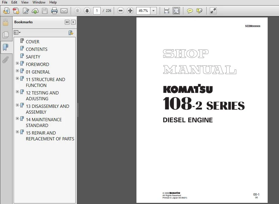
Komatsu Diesel Engine 108-2 Series Shop Manual
Description
Komatsu Diesel Engine 108-2 Series Shop Manual
FILE DETAILS:
Komatsu Diesel Engine 108-2 Series Shop Manual
Brands: Komatsu
Equipment Type: Diesel Engine
Manuals Type: Shop Manual
Machine Model: 108-2 Series Diesel Engine
Book Code: SEBM006906
Language: English
Pages: 226
File Format: Portable Document Format (PDF)
KOMATSU DIESEL ENGINE 108-2 SERIES SHOP MANUAL_SEBM006906 – PDF DOWNLOAD:
IMAGES PREVIEW OF THE MANUAL:
DESCRIPTION:
Komatsu Diesel Engine 108-2 Series Shop Manual
FOREWORD:
GENERAL:
- This shop manual has been prepared as an aid to improve the quality of repairs by giving the serviceman an accurate understanding of the product and by showing him the correct way to perform repairs and make judgements. Make sure you understand the contents of this manual and use it to full effect at every opportunity.
- This shop manual mainly contains the necessary technical information for operations performed in a service workshop. For ease of understanding, the manual is divided into the following chapters; these chapters are further divided into the each main group of components.
STRUCTURE AND FUNCTION:
This section explains the structure and function of each component. It serves not only to give an understanding of the structure, but also serves as reference material for troubleshooting. In addition, this section may contain hydraulic circuit diagrams, electric circuit diagrams, and maintenance standards.
TESTING AND ADJUSTING:
This section explains checks to be made before and after performing repairs, as well as adjustments to be made at completion of the checks and repairs. Troubleshooting charts correlating “Problems” with “Causes” are also included in this section.
DISASSEMBLY AND ASSEMBLY:
This section explains the procedures for removing, installing, disassembling and assembling each component, as well as precautions for them.
MAINTENANCE STANDARD:
This section gives the judgment standards for inspection of disassembled parts. The contents of this section may be described in STRUCTURE AND FUNCTION.
OTHERS:
This section mainly gives hydraulic circuit diagrams and electric circuit diagrams. In addition, this section may give the specifications of attachments and options together.
TABLE OF CONTENTS:
Komatsu Diesel Engine 108-2 Series Shop Manual
COVER.......................................................................................  1
CONTENTS....................................................................................  4
SAFETY......................................................................................  5
FOREWORD....................................................................................  7
	GENERAL.................................................................................  7
	HOW TO READ THE SHOP MANUAL.............................................................  8
	HOISTING INSTRUCTIONS...................................................................  9
	METHOD OF DISASSEMBLING, CONNECTING PUSH-PULL TYPE COUPLER.............................. 10
	COATING MATERIALS....................................................................... 12
	STANDARD TIGHTENING TORQUE.............................................................. 14
	ELECTRICAL WIRE CODE.................................................................... 17
	CONVERSION TABLE........................................................................ 18
	UNITS................................................................................... 24
01 GENERAL.................................................................................. 25
	APPLICABLE MACHINE...................................................................... 26
	SPECIFICATIONS.......................................................................... 28
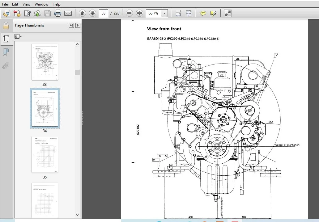
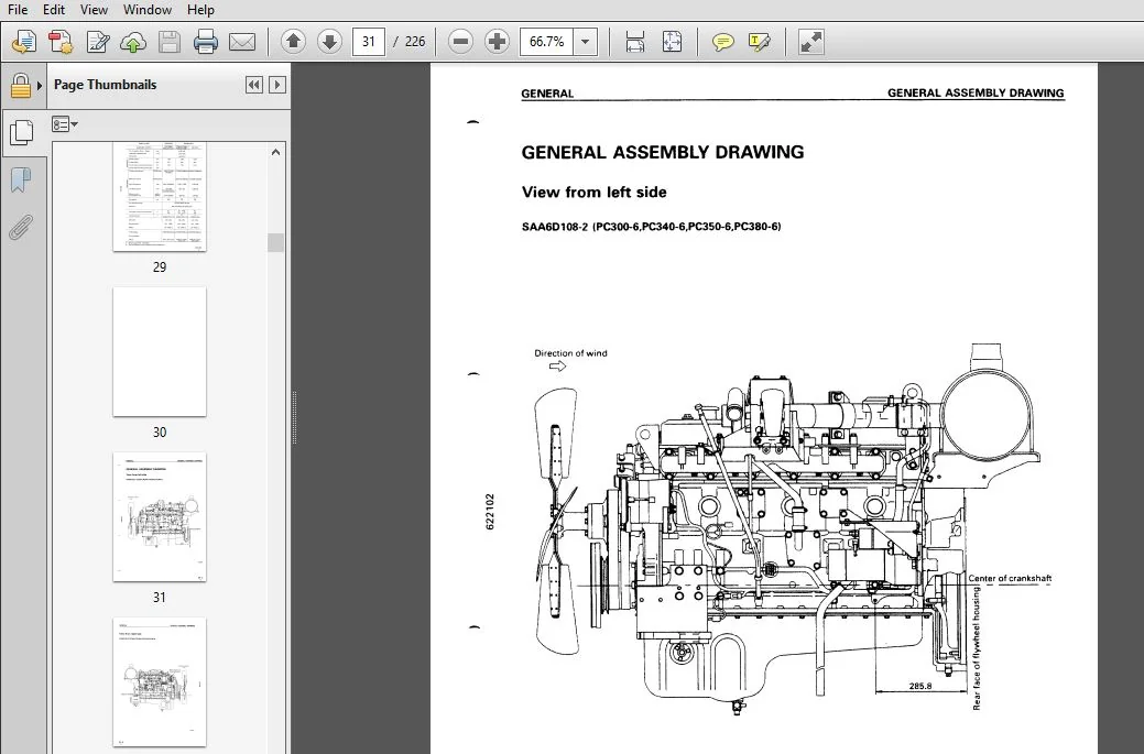
	GENERAL ASSEMBLY DRAWING................................................................ 31
	ENGINE PERFORMANCE CURVE................................................................ 35
	WEIGHT TABLE............................................................................ 37
11 STRUCTURE AND FUNCTION................................................................... 39
	GENERAL STRUCTURE....................................................................... 40
	INTAKE AND EXHAUST SYSTEM............................................................... 42
		AFTERCOOLER......................................................................... 42
		AIR-COOLED AFTERCOOLER MOUNT........................................................ 43
		AIR CLEANER......................................................................... 47
		ELECTRONIC DUST INDICATOR........................................................... 48
		TURBOCHARGER........................................................................ 49
	ENGINE BODY............................................................................. 52
		CYLINDER HEAD....................................................................... 52
		CYLINDER BLOCK...................................................................... 54
		MAIN REVOLVING SYSTEM............................................................... 56
		TIMING GEAR......................................................................... 58
		VALVE MECHANISM..................................................................... 60
		FLYWHEEL AND FLYWHEEL HOUSING....................................................... 62
	LUBRICATION SYSTEM...................................................................... 64
		LUBRICATION SYSTEM CHART............................................................ 64
		OIL PUMP............................................................................ 65
		OIL FILTER.......................................................................... 66
		OIL COOLER.......................................................................... 67
	FUEL SYSTEM............................................................................. 69
		FUEL SYSTEM CHART................................................................... 69
		FUEL INJECTION PUMP................................................................. 70
		SPEED CONTROL LEVER ANGLE........................................................... 71
		BOOST COMPENSATOR DEVICE............................................................ 72
		FUEL INJECTION NOZZLE............................................................... 73
		FUEL FILTER......................................................................... 74
		FUEL INJECTION PUMP DRIVE CASE...................................................... 77
	COOLING SYSTEM.......................................................................... 84
		COOLING SYSTEM, CHART............................................................... 84
		WATER PUMP.......................................................................... 86
		THERMOSTAT.......................................................................... 88
	ELECTRICAL SYSTEM....................................................................... 89
		WIRING DIAGRAM...................................................................... 89
		ALTERNATOR.......................................................................... 92
		STARTING MOTOR...................................................................... 95
		OIL PRESSURE SWITCH................................................................. 97
		RELAY SWITCH........................................................................ 97
		GLOW PLUG........................................................................... 98
12 TESTING AND ADJUSTING.................................................................... 99
	INTAKE AND EXHAUST SYSTEM...............................................................101
		ADJUSTING VALVE CLEARANCE...........................................................101
	ENGINE BODY.............................................................................102
		MEASURING COMPRESSION PRESSURE......................................................102
	FUEL SYSTEM.............................................................................103
		TESTING AND ADJUSTING FUEL INJECTION TIMING.........................................103
		PROCEDURE FOR ADJUSTING FUEL CUT SOLENOID LINKAGE...................................107
		PROCEDURE FOR ADJUSTING ENGINE STOP MOTOR CABLE.....................................108
	PERFORMANCE TEST........................................................................109
		RUNNING IN STANDARD.................................................................109
		PERFORMANCE TEST CRITERIA...........................................................110
	FUEL INJECTION PUMP CALIBRATION DATA....................................................112
	TROUBLESHOOTING.........................................................................120
		POINTS TO REMEMBER WHEN TROUBLESHOOTING.............................................121
		METHOD OF USING TROUBLESHOOTING CHART...............................................123
		S-1 STARTING PERFORMANCE IS POOR (STARTING ALWAYS TAKES TIME) ......................127
		S-2 ENGINE DOES NOT START...........................................................128
			(1) ENGINE DOES NOT TURN........................................................128
			(2) ENGINE TURNS BUT NO EXHAUST GAS COMES OUT (FUEL IS NOT BEING INJECTED)......129
			(3) EXHAUST GAS COMES OUT BUT ENGINE DOES NOT START (FUEL IS BEING INJECTED)....130
		S-3 ENGINE DOES NOT PICK UP SMOOTHLY (FOLLOW-UP IS POOR)............................131
		S-4 ENGINE STOPS DURING OPERATIONS..................................................132
		S-5 ENGINE DOES NOT ROTATE SMOOTHLY (HUNTING).......................................133
		S-6 ENGINE LACKS OUTPUT (NO POWER)..................................................134
		S-7 EXHAUST GAS IS BLACK (INCOMPLETE COMBUSTION)....................................135
		S-8 OIL CONSUMPTION IS EXCESSIVE (OR EXHAUST GAS IS BLUE)...........................136
		S-9 OIL BECOMES CONTAMINATED QUICKLY................................................137
		S-10 FUEL CONSUMPTION IS EXCESSIVE..................................................138
		S-11 OIL IS IN COOLING WATER, OR WATER SPURTS BACK, OR WATER LEVEL GOES DOWN........139
		S-12 OIL PRESSURE LAMP LIGHTS UP (DROP IN OIL PRESSURE).............................140
		S-13 OIL LEVEL RISES................................................................141
		S-14 WATER TEMPERATURE BECOMES TOO HIGH (OVERHEATING) ..............................142
		S-15 ABNORMAL NOISE IS MADE.........................................................143
		S-16 VIBRATION IS EXCESSIVE.........................................................144
	TOOLS FOR TESTING, ADJUSTING, AND TROUBLESHOOTING.......................................145
	TESTING AND ADJUSTING DATA..............................................................147
13 DISASSEMBLY AND ASSEMBLY.................................................................150
	OVERALL DISASSEMBLY.....................................................................151
	OVERALL ASSEMBLY........................................................................163
14 MAINTENANCE STANDARD.....................................................................186
	INTAKE AND EXHAUST SYSTEM...............................................................187
		TURBOCHARGER........................................................................187
	ENGINE BODY.............................................................................188
		CYLINDER HEAD.......................................................................188
		VALVE AND VALVE GUIDE...............................................................189
		ROCKER ARM, PUSH ROD AND TAPPET.....................................................191
		CYLINDER LINER......................................................................192
		CYLINDER BLOCK......................................................................193
		CRANKSHAFT..........................................................................195
		CAMSHAFT............................................................................196
		PISTON, PISTON RING AND PISTON PIN..................................................197
		CONNECTING ROD......................................................................198
		TIMING GEAR.........................................................................199
		FLYWHEEL AND FLYWHEEL HOUSING.......................................................200
	LUBRICATION SYSTEM......................................................................201
		OIL PUMP............................................................................201
		REGULATOR VALVE.....................................................................202
		SAFETY VALVE........................................................................202
	COOLING SYSTEM..........................................................................203
		WATER PUMP AND THERMOSTAT...........................................................203
15 REPAIR AND REPLACEMENT OF PARTS..........................................................204
	REPAIRING MOUNTING FACE OF CYLINDER HEAD BY GRINDING....................................205
	REPLACING VALVE SEAT INSERTS............................................................206
	PRESSURE TEST...........................................................................210
	REPLACING VALVE GUIDE...................................................................211
	GRINDING THE VALVE......................................................................212
	REPLACING CAM BUSHING...................................................................213
	REPLACING CRANK GEAR....................................................................215
	REPLACING CAM GEAR......................................................................215
	REPLACING FLYWHEEL RING GEAR............................................................216
	REPLACING MAIN BEARING CAP..............................................................217
	GRINDING CRANKSHAFT.....................................................................218
	REPLACING ENGINE REAR SEAL..............................................................223
	REPLACING CONNECTING ROD SMALL END BUSHING..............................................226
PLEASE NOTE:
- This is the SAME exact manual used by your dealers to fix your vehicle.
- The same can be yours in the next 2-3 mins as you will be directed to the download page immediately after paying for the manual.
- Any queries / doubts regarding your purchase, please feel free to contact [email protected]



