
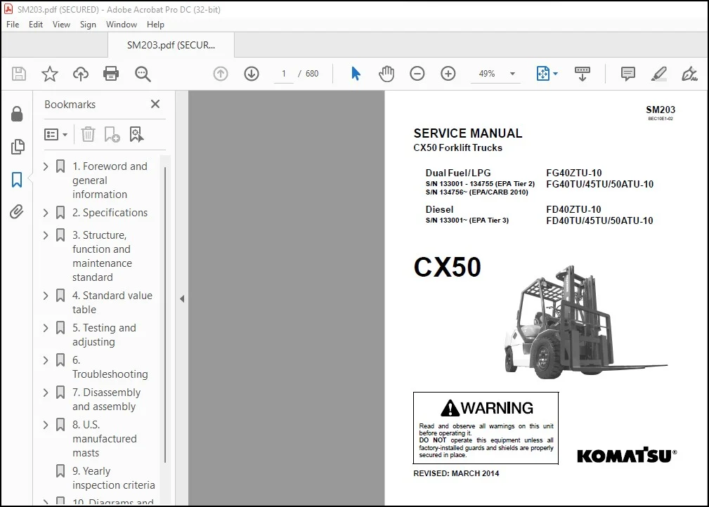
Komatsu Dual Fuel/LPG FG40ZTU-10 FG40TU/45TU/50ATU-10 Diesel FD40ZTU-10 FD40TU/45TU/50ATU-10 CX50 Forklift Trucks Service Manual SM203 BEC10E1-02 – PDF DOWNLOAD
Original price was: $86.95.$31.95Current price is: $31.95.
Komatsu Dual Fuel/LPG FG40ZTU-10 FG40TU/45TU/50ATU-10 Diesel FD40ZTU-10 FD40TU/45TU/50ATU-10 CX50 Forklift Trucks Service Manual SM203 BEC10E1-02 – PDF DOWNLOAD
Description
Komatsu Dual Fuel/LPG FG40ZTU-10 FG40TU/45TU/50ATU-10 Diesel FD40ZTU-10 FD40TU/45TU/50ATU-10 CX50 Forklift Trucks Service Manual SM203 BEC10E1-02 – PDF DOWNLOAD
IMAGES PREVIEW OF THE MANUAL:
DESCRIPTION:
Komatsu Dual Fuel/LPG FG40ZTU-10 FG40TU/45TU/50ATU-10 Diesel FD40ZTU-10 FD40TU/45TU/50ATU-10 CX50 Forklift Trucks Service Manual SM203 BEC10E1-02 – PDF DOWNLOAD
Dual Fuel/LPG FG40ZTU-10
S/N 133001 – 134755 (EPA Tier 2) FG40TU/45TU/50ATU-10
S/N 134756~ (EPA/CARB 2010)
Diesel FD40ZTU-10
S/N 133001~ (EPA Tier 3) FD40TU/45TU/50ATU-10
General precautions:
Mistakes in operation are extremely dangerous. Read the Operation and Maintenance Manual carefully
before operating the lift truck. In addition, read this manual carefully before starting work.
1. Before carrying out any greasing or repairs, read all the safety labels stuck to the lift truck. For the locations of
the safety labels and detailed explanation of precautions, see the Operation and Maintenance Manual.
2. Decide a place in the repair workshop to keep tools and removed parts. Always keep the tools and parts in their
correct places. Always keep the work area clean and make sure that there is no dirt, water, or oil on the floor.
Smoke only in the areas provided for smoking. Never smoke while working.
3. When carrying out any operation, always wear safety shoes and helmet. Do not wear loose work clothes, or
clothes with buttons missing.
a. Always wear safety glasses when hitting parts with a hammer.
b. Always wear safety glasses when grinding parts with a grinder, etc.
4. When carrying out any operation with 2 or more workers, always agree on the operating procedure before
starting. Always inform your fellow workers before starting any step of the operation. Before starting work, hang
UNDER REPAIR warning signs in the operator’s compartment.
5. Only qualified workers must carry out work and operation which require license or qualification.
6. Keep all tools in good condition. Learn the correct way to use them, and use the proper ones of them. Before
starting work, thoroughly check the tools, lift truck, service car, etc.
7. If welding repairs are needed, always have a trained and experienced welder carry out the work. When carrying
out welding work, always wear welding gloves, apron, shielding goggles, cap and other clothes suited for
welding work.
8. Before starting work, warm up your body thoroughly to start work under good condition.
9. Avoid working continuously for long hours and take rests at proper intervals to keep the good condition. Take
rests in a fixed safe place.
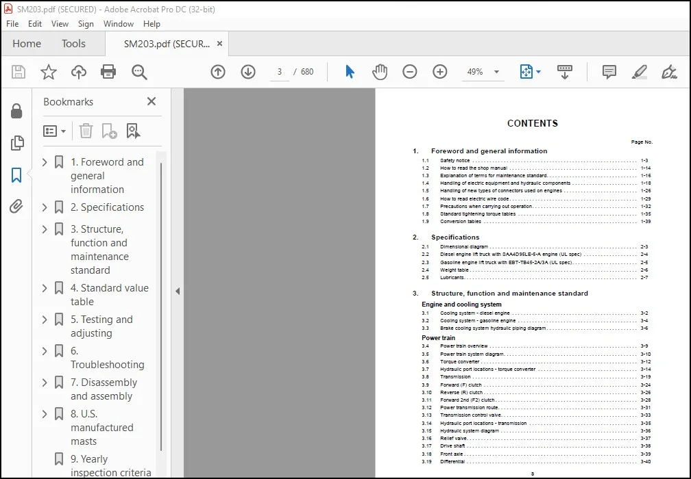
TABLE OF CONTENTS:
Komatsu Dual Fuel/LPG FG40ZTU-10 FG40TU/45TU/50ATU-10 Diesel FD40ZTU-10 FD40TU/45TU/50ATU-10 CX50 Forklift Trucks Service Manual SM203 BEC10E1-02 – PDF DOWNLOAD
1 Foreword and general information
1 1 Safety notice 1-3
1 2 How to read the shop manual 1-14
1 3 Explanation of terms for maintenance standard 1-16
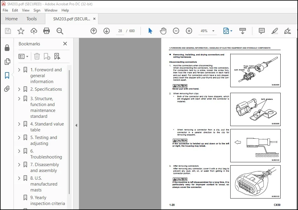
1 4 Handling of electric equipment and hydraulic components 1-18
1 5 Handling of new types of connectors used on engines 1-26
1 6 How to read electric wire code 1-29
1 7 Precautions when carrying out operation 1-32
1 8 Standard tightening torque tables 1-35
1 9 Conversion tables 1-39
2 Specifications
2 1 Dimensional diagram 2-3
2 2 Diesel engine lift truck with SAA4D95LE-5-A engine (UL spec) 2-4
2 3 Gasoline engine lift truck with EBT-TB45-2A/3A (UL spec) 2-5
2 4 Weight table 2-6
2 5 Lubricants 2-7
3 Structure, function and maintenance standard
Engine and cooling system
3 1 Cooling system – diesel engine 3-2
3 2 Cooling system – gasoline engine 3-4
3 3 Brake cooling system hydraulic piping diagram 3-6
Power train
3 4 Power train overview 3-9
3 5 Power train system diagram 3-10
3 6 Torque converter 3-12
3 7 Hydraulic port locations – torque converter 3-14
3 8 Transmission 3-19
3 9 Forward (F) clutch 3-24
3 10 Reverse (R) clutch 3-26
3 11 Forward 2nd (F2) clutch 3-28
3 12 Power transmission route 3-31
3 13 Transmission control valve 3-33
3 14 Hydraulic port locations – transmission 3-35
3 15 Hydraulic system diagram 3-36
3 16 Relief valve 3-37
3 17 Drive shaft 3-38
3 18 Front axle 3-39
3 19 Differential 3-40
4
CONTENTS
3 20 Final drive 3-44
Steering system
3 21 Steering piping diagram 3-49
3 22 Orbital valve 3-50
3 23 Power steering cylinder 3-51
Brake system
3 24 Brake control 3-55
3 25 Brake piping diagram 3-56
3 26 Service brake 3-57
3 27 Accumulator charge valve 3-59
3 28 Brake valve 3-64
3 29 Slack adjuster 3-67
3 30 Accumulator (for brake) 3-70
3 31 Parking brake 3-71
Undercarriage and frame
3 32 Rear axle 3-75
3 33 Hydraulic tank piping diagram 3-76
3 34 Frame 3-77
Hydraulic system
3 35 Control valve piping diagram 3-81
3 36 Work equipment piping diagram 3-82
3 37 Attachment piping diagram 3-83
3 38 Hydraulic pump 3-84
3 39 LS valve 3-89
3 40 Unload valve 3-90
3 41 Control valve 3-91
3 42 3-spool valve 3-92
3 43 Closed center Load Sensing System (CLSS) 3-97
3 44 Function and operation of each valve 3-99
Work equipment
3 45 Tilt cylinder 3-115
3 46 Lift cylinder – Japan manufacture 3-116
3 47 Mast – Japan manufacture 3-117
3 48 Fork carriage – Japan manufacture 3-124
3 49 Fork – Japan manufacture 3-125
Electric devices Part 1
3 50 Accelerator pedal sensor 3-129
3 51 ISO controller – Operator Presence Sensing (OPS) system 3-131
3 52 Instrument panel 3-138
3 53 Engine starting circuit 3-140
3 54 Engine stopping circuit 3-142
3 55 Electrical system wiring diagram 3-143
5
CONTENTS
Electric devices Part 2
3 56 Sensors 3-147
3 57 Switches 3-149
3 58 Lamps 3-155
3 59 Horn and buzzer 3-157
3 60 Flasher 3-160
3 61 F/R solenoid valve and F2 solenoid valve 3-161
3 62 Relay box 3-162
3 63 Resistor 3-168
3 64 Diode 3-169
3 65 Fuse 3-180
3 66 Battery 3-182
4 Standard value table
4 1 Lift truck with SAA4D95LE-5-A engine (UL spec) 4-3
4 2 Lift truck with EBT-TB45-2A/3A engine (UL spec) 4-5
5 Testing and adjusting
5 1 Check of troubleshooting software functions and failure codes 5-3
5 2 Hydraulic piping pressure release procedure 5-6
5 3 Replacement of engine oil and engine oil filter 5-7
5 4 Replacement of fuel filter 5-8
5 5 Cleaning of radiator 5-11
5 6 Check of air cleaner and replacement of cleaner element 5-12
5 7 Oil level check and oil replacement of differential case 5-13
5 8 Oil replacement and strainer cleaning of Torqflow transmission 5-14
5 9 Testing power train oil pressure 5-15
5 10 Check of hydraulic tank 5-18
5 11 Measurement of wear amount of service brake disc 5-20
5 12 Check of parking brake 5-21
5 13 Air bleeding procedure 5-22
5 14 Adjustment of brake pedal 5-23
5 15 Adjustment of inching pedal 5-24
5 16 Measurement of cylinder hydraulic drift and hydraulic forward drift 5-25
5 17 Adjustment of mast – Japan manufacture 5-26
5 18 Adjustment of fork carriage – Japan manufacture 5-29
5 19 Check of drive shaft for looseness, play and damage 5-31
5 20 Check of diode 5-32
6 Troubleshooting
General information on troubleshooting
6 1 Points to remember when troubleshooting 6-3
6 2 Sequence of events in troubleshooting 6-4
6
CONTENTS
6 3 Testing before troubleshooting 6-5
6 4 Classification and procedures of troubleshooting 6-6
6 5 Phenomena indicating trouble and troubleshooting codes 6-7
6 6 Information contained in troubleshooting table 6-13
6 7 Locations of fuses 6-15
Failure codes: ISO controller (UL spec)
6 8 Failure code display by ISO controller 6-23
6 9 Failure code [[!]: 1 flashing, [N]: Flashing, [L]: Flashing] 6-26
6 10 Failure code [!]: 2 flashings, [N]: Flashing, [L]: OFF 6-28
6 11 Failure code [!]: 3 flashings, [N]: OFF, [L]: OFF 6-30
6 12 Failure code [[!]: 4 flashings, [N]: OFF, [L]: Flashing] 6-34
6 13 Failure code [[!]: 4 flashings, [N]: Flashing, [L]: Flashing] 6-36
6 14 Failure code [[!]: 5 flashings, [N]: OFF, [L]: Flashing] 6-38
6 15 Failure code [[!]: 5 flashings, [N]: Flashing, [L]: Flashing] 6-40
6 16 Failure code [[!]: 6 flashings, [N]: Flashing, [L]: Flashing] 6-42
6 17 Failure code [[!]: 7 flashings, [N]: Flashing, [L]: Flashing] 6-44
Electrical system (E-mode) SAA4D95LE-5-A engine (UL spec)
6 18 E-1 Engine does not start 6-47
6 19 E-2 Engine does not stop 6-50
6 20 E-3 Lift truck cannot travel 6-52
6 21 E-4 Parking brake reminder alarm does not sound or does not stop sounding 6-55
6 22 E-5 Travel direction is not changed normally 6-57
6 23 E-6 Lift truck cannot move work equipment 6-60
6 24 E-7 Work equipment cannot be locked 6-62
6 25 E-8 Headlamp, clearance lamp and tail lamp do not light or go off 6-64
6 26 E-9 Turn signal lamps do not light or go off 6-66
6 27 E-10 Brake lamps do not light or go off 6-68
6 28 E-11 Backup lamps do not light or go off 6-70
6 29 E-12 Backup buzzer (optional) does not sound or does not stop sounding 6-72
6 30 E-13 Horn does not sound or does not stop sounding 6-74
6 31 E-14 Fuel level is not displayed normally 6-76
Electrical system (E-mode) EBT-TB45-2A/3A engine (UL spec)
6 32 E-1 Engine does not start 6-81
6 33 E-2 Engine does not stop 6-88
6 34 E-3 Lift truck cannot travel 6-90
6 35 E-4 Parking brake reminder alarm does not sound or does not stop sounding 6-90
6 36 E-5 Travel direction is not changed normally 6-90
6 37 E-6 Lift truck cannot move work equipment 6-90
6 38 E-7 Work equipment cannot be locked 6-90
6 39 E-8 Headlamp, clearance lamp and, tail lamp do not light or go off 6-90
6 40 E-9 Turn signal lamps do not light or go off 6-90
6 41 E-10 Brake lamps do not light or go off 6-90
6 42 E-11 Backup lamps do not light or go off 6-90
7
CONTENTS
6 43 E-12 Backup buzzer (optional) does not sound or does not stop sounding 6-90
6 44 E-13 Horn does not sound or does not stop sounding 6-90
6 45 E-14 Fuel (Gasoline) level is not displayed normally 6-90
Hydraulic and mechanical system (H-mode)
6 46 Method of using troubleshooting table 6-93
6 47 Table of failure modes and causes 6-96
7 Disassembly and assembly
General information
7 1 Using this chapter 7-3
7 2 Special tool list 7-4
7 3 How to use LOCTITE 7-8
Engine and cooling system
7 4 Power train removal 7-11
7 5 Power train installation 7-15
Power train components
7 6 Front axle removal 7-19
7 7 Front axle installation 7-23
7 8 Power train centering 7-26
7 9 Transmission disassembly 7-30
7 10 Transmission assembly 7-34
7 11 Torque converter disassembly 7-37
7 12 Torque converter component parts 7-40
7 13 Torque converter assembly 7-42
7 14 Drive shaft 7-43
7 15 Differential disassembly 7-44
7 16 Differential assembly 7-48
7 17 Axle housing disassembly 7-57
7 18 Axle housing assembly 7-61
7 19 Parking brake 7-68
7 20 Rear axle disassembly 7-69
7 21 Rear axle assembly 7-70
7 22 Power steering cylinder disassembly 7-73
7 23 Power steering cylinder assembly 7-75
7 24 Brake pedal 7-76
7 25 Brake valve disassembly 7-77
7 26 Brake valve assembly 7-79
Hydraulic equipment
7 27 Steering valve 7-83
7 28 Control valve 7-87
7 29 Lift cylinder – Japan manufacture 7-93
7 30 Tilt cylinder 7-97
8
CONTENTS
Work equipment
7 31 Mast removal – Japan manufacture 7-105
7 32 Mast installation – Japan manufacture 7-105
Electric devices
7 33 Combination switch component parts 7-113
8 U S manufactured masts
80D/100D/110D-MS 2-Stage Masts
8 1 Introduction 8-2
8 2 Installation Instructions 8-3
8 3 Periodic Maintenance 8-8
8 4 Troubleshooting 8-9
8 5 Service 8-10
80D/100D/110D-MT 3-Stage Masts
8 1 Introduction 8-30
8 2 Installation Instructions 8-31
8 3 Periodic Maintenance 8-46
8 4 Troubleshooting 8-47
8 5 Service 8-48
D-Series Sideshifter
E-Series Sideshifter
9 Yearly inspection criteria
10 Diagrams and drawings
Hydraulic circuit
CX50 Hydraulic Circuit Diagram 10-3
Electrical circuit – UL spec
CX50 Electrical Diagram – TB45 Engine – Dual Fuel – Tier 2 – S/N 133001 – 134755 10-5
CX50 Electrical Diagram – TB45 Engine – Dual Fuel – CARB 2010 – S/N 134756~ 10-7
CX50 Electrical Diagram – TB45 Engine – LPG – Tier 2 – S/N 133001 – 134755 10-9
CX50 Electrical Diagram – TB45 Engine – LPG – CARB 2010 – S/N 134756~ 10-11
CX50 Electrical Diagram – SAA4D95LE Engine – Diesel – Tier 3 10-13
Need help? Contact: [email protected]
https://vimeo.com/747538288
PLEASE NOTE:
- This is the SAME exact manual used by your dealers to fix your vehicle.
- The same can be yours in the next 2-3 mins as you will be directed to the download page immediately after paying for the manual.
- Any queries / doubts regarding your purchase, please feel free to contact [email protected]
S.V



