Komatsu Dump Truck 930E-5 Shop Manual CEBM039400 PDF
$35.95
Komatsu Dump Truck 930E-5 Shop Manual CEBM039400 – PDF DOWNLOAD
SERIAL NUMBERS 950E-5
A40067 – A40215
Description
Komatsu Dump Truck 930E-5 Shop Manual CEBM039400 – PDF DOWNLOAD
FILE DETAILS:
Komatsu Dump Truck 930E-5 Shop Manual CEBM039400 – PDF DOWNLOAD
Language : English
Pages :1131
Downloadable : Yes
File Type : PDF
DESCRIPTION:
Komatsu Dump Truck 930E-5 Shop Manual CEBM039400 – PDF DOWNLOAD
SERIAL NUMBERS 950E-5
A40067 – A40215
FOREWORD
HOW TO READ THE SHOP MANUAL
REMARK
Some attachments and options given in this shop manual may not be available in some areas. If they are required, speak to your Komatsu distributor.
• The materials and specifications are subject to change without notice.
Komatsu shop manuals are available for the “machine part”. For detailed information on the “engine part” or “drive system part”, see the shop manual from the original equipment manufacturer (OEM).
• Actual machine may differ from the images which are given in this manual. A typical model is shown in the illustrations of this shop manual.
Composition of the shop manual
This manual supports quality repair through education of the product, correct repair procedures, and assistance with repair decisions.
Understand the content of this manual and use it at every opportunity.
This shop manual contains technical information necessary to perform services in the workshops. It is organized into chapters for ease of use.
00 INDEX AND FOREWORD
This section describes the index, foreword, safety, and basic information.
01 SPECIFICATIONS
This section describes the specifications of the machine such as dimensions, performance, component weights. and lubricant charts.
10 STRUCTURE AND FUNCTION
This section describes the structure and operation of each component with respect to each system.
“STRUCTURE AND FUNCTION” is helpful to understand the structure of each component and to do the troubleshooting procedure.
20 STANDARD VALUE TABLE
This section describes the standard values for a new machine and failure criteria for testing, adjusting, and troubleshooting. Use the “STANDARD VALUE TABLE” to check the standard values for testing and adjusting, and troubleshooting.
30 TESTING AND ADJUSTING
This section describes the measurement tools and methods to test and adjust each part. The standard values
and repair limit for TESTING AND ADJUSTING are given in the “STANDARD VALUE TABLE”.
40 TROUBLESHOOTING
This section describes how to troubleshoot and repair failures in the machine.
Troubleshooting steps are sorted by failure mode.
Troubleshooting steps correlate “Problems” to “Causes” in this section.
50 DISASSEMBLY AND ASSEMBLY
This section describes the special tools, work procedures, and safety precautions necessary for removal, installation, disassembly, and assembly of the components and parts.
60 MAINTENANCE STANDARD
This section describes the maintenance standard value of each component. The maintenance standard shows the criteria and remedies for disassembly and assembly.
TABLE OF CONTENTS:
Komatsu Dump Truck 930E-5 Shop Manual CEBM039400 – PDF DOWNLOAD
ERIAL NUMBERS 950E-5
A40067 – A40215
COVER 1
00 CONTENTS AND FOREWORD 3
Foreword 19
How to Read the Shop Manual 19
Safety Alert Symbol and Signal Words 20
General Precautions Common to Operation and Maintenance 21
Preparations for Safe Operation 21
Fire and Explosion Prevention 23
Precautions When Getting On or Off the Machine 24
Precautions for Cab and Working Around Machine 27
Precautions for Diesel Exhaust Fluid (DEF) 28
Operation Precautions 31
Precautions at Jobsite 31
Precautions in Starting Engine 32
Precautions During Operation 34
Maintenance Precautions 36
Precautions Before Inspection and Maintenance 36
Precautions During Inspection and Maintenance 41
Precautions for Electrical Equipment 48
Primary Causes of Wiring Harness Failure 49
Control Cabinet Capacitor Discharge 51
Hydraulic Equipment Precautions 52
01 SPECIFICATIONS 55
Specifications 56
Specifications: 930E-5 56
Weight Table: 930E-5 57
Recommended Fuel, Coolant, and Lubricant 59
Suspension Cylinder Oil and Nitrogen Specifications 59
Wheel Motor Oil Specifications 61
10 STRUCTURE AND FUNCTION 63
Steering System 64
Steering System Layout 64
Steering System Operation 64
Steering Bleeddown Manifold 66
Steering Control Unit 67
Steering Accumulators (Piston Type) 68
Steering/Brake Pump Operation 68
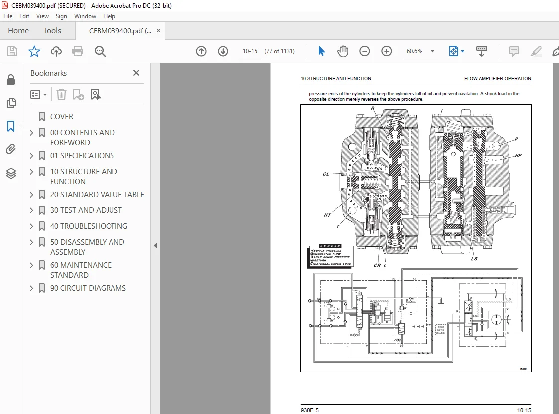
Flow Amplifier Operation 70
Hoist System 78
Hoist System Layout 78
Hoist System Operation 79
Hoist Control Valve 80
Hoist Pilot Valve 82
Brake System 83
Service Brake System Layout 83
Hydraulic Brake Cabinet Layout 84
Service Brake Operation 84
Parking Brake Operation 85
Brake Lock Operation 85
Secondary Braking and Auto Apply 86
Electrical System, 24V 87
Battery Power Supply 87
Battery Disconnect Switches 88
Engine Starting System 89
Auxiliary Control Cabinet Components 90
Body-Up Switch 92
Hoist Limit Switch 93
Automatic Lubrication (Auto Lube) System 94
Automatic Lubrication (Auto Lube) Grease Pump and Reservoir 94
Automatic Lubrication (Auto Lube) System Operation 95
Suspensions 97
Engine Emissions After-Treatment System Operations 98
20 STANDARD VALUE TABLE 101
Standard Value Table 102
30 TEST AND ADJUST 107
Hydraulic Systems 108
Hydraulic System Checkout Procedures 108
Hydraulic System Checkout Sheet 120
Steering System Leakage Check 123
Toe-In Adjustment 124
Hoist Cylinder Leakage Test 125
Steering Cylinder Leakage Test 125
Checking the Steering/Brake Pump Control Pressures 126
Adjusting the Steering/Brake Pump Control Pressures 127
High Altitude Steering/Brake Pump Adjustment 129
Brake System 130
Brake System Checkout Procedures 130
Brake System Checkout Sheet 140
Brake System Leakage Check 147
Brake Piston Leakage Test 148
Parking Brake Piston Leakage Test 149
Brake Floating Seal Pressure Test 149
Oil Separation Seal Pressure Test (Air Pressure Method) 150
Oil Separation Seal Pressure Test (Oil Pressure Method) 150
Wet Disc Brake Bleeding Procedure 151
Parking Brake Bleeding Procedure 151
Wet Disc Brake Wear Inspection 152
Parking Brake Wear Inspection 154
Accumulators and Suspensions 155
Bladder Accumulator Charging Procedure 155
Bladder Accumulator Leakage Test 156
Bladder Accumulator Storage 157
Piston Accumulator Charging Procedure 158
Piston Accumulator Leakage Test 159
Piston Accumulator Storage 160
Check for Improper Suspension Charge 161
Suspension Oiling and Charging Procedures 162
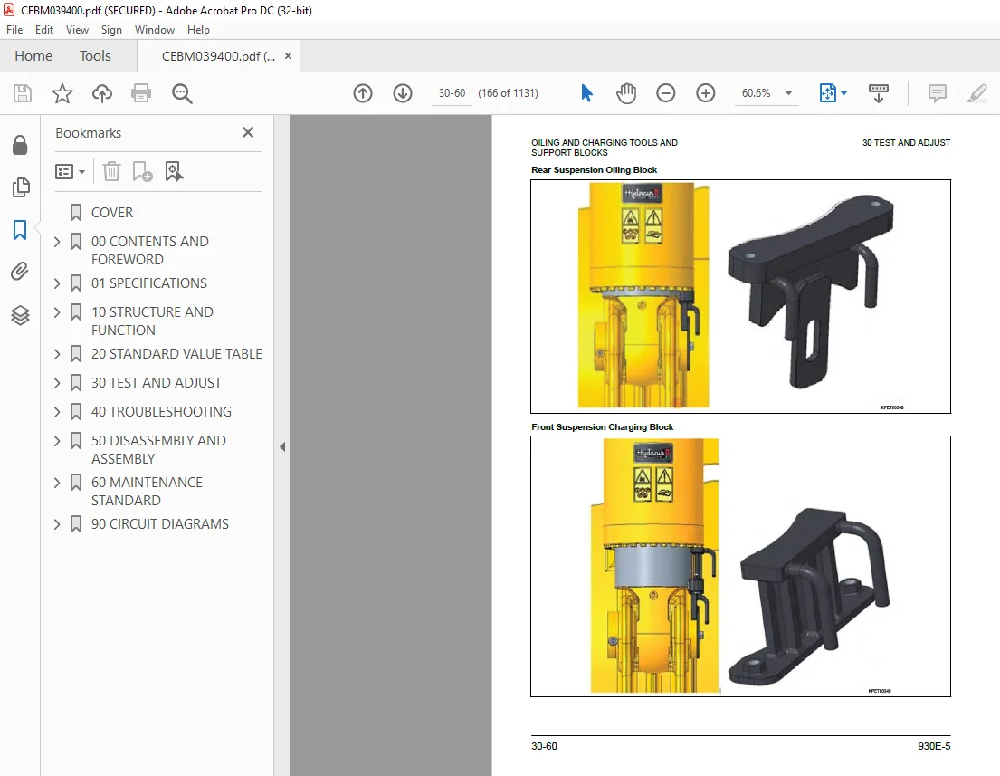
Oiling and Charging Tools and Support Blocks 163
Nitrogen Charging Kit Installation 167
Nitrogen Charging Kit Removal 167
Front Suspension Oiling and Charging 168
Rear Suspension Oiling and Charging 171
Suspension Pressure Test 174
Automatic Lubrication (Auto Lube) System 175
Prime the Auto Lube Pump 175
Prime the Auto Lube Grease Lines 175
Auto Lube System Checkout 176
Adjust the Auto Lube Cycle Timing (original IM only) 177
Adjust the Auto Lube Cycle Timing (IM2 only) 178
Cab Air Conditioning 179
Refrigerant Leak Detection 180
A/C System Performance Test 180
Check the A/C System Oil 181
A/C System Flushing Procedure 182
Manifold Gauge Set Installation 183
Refrigerant: Recycled vs Reclaimed 184
Refrigerant Recovery Procedure 184
Evacuate the A/C System 184
Charge the A/C System 185
Electrical Systems 187
Shutdown Procedure for Drive System Service 187
Electrical System Checkout Procedures 188
Visual Checks 188
Resistance Checks 188
Voltage Checks 188
Truck Function Checks 191
Interface Module (IM) Checks 192
KOMTRAX Plus II Checks 192
Payload Meter (PLM) Checks 192
Drive System Checks 192
Engine Delayed Shutdown Smart Timer Check 193
Hoist Limit Switch Check 193
Electrical System Checkout Sheet 194
Interface Module (IM) 196
Interface Module Software and Tools 196
Interface Module Checkout Procedures 196
Setup for IM Realtime Monitor Software 196
Checking Digital Inputs to the IM 197
Checking Analog Inputs to the IM 198
Checking Serial Communication to the IM 199
Checking Outputs from the IM 199
Interface Module Checkout Sheet 200
Interface Module 2 (IM2) 203
Interface Module 2 Software and Tools 203
Program the IM2 Controller 203
Interface Module 2 Checkout Procedures 205
Check for IM Fault Codes 205
Checking Digital Inputs to the IM2 206
Checking Analog Inputs to the IM2 207
Checking Serial Communication to the IM 208
Checking Outputs from the IM2 208
Interface Module 2 Checkout Sheet 209
Payload Meter IV 212
Payload Meter IV Software and Tools 212
Payload Meter IV System Configuration 212
Configuring a Static IP Address 212
Payload Meter IV Software Installation 215
Payload Meter IV Data Downloading 215
Payload Meter IV Checkout Procedure 216
Payload Meter IV Checkout Sheet 222
KOMTRAX Plus II 223
KOMTRAX Plus II Software and Tools 223
Komtrax Plus II Controller Ethernet Connection 223
KOMTRAX Plus II Configuration 224
GPS Connection Test 227
Satellite Connection Test 229
Komtrax Plus II System Initialization 232
KomVision 234
KomVision Setup and Calibration Requirements 234
KomVision Initial Setup and Checkout Procedure 234
KomVision Checkout Sheet 240
KomVision Calibration Sheets 242
Calibration Sheet Layout 242
Unfold and Fold Calibration Sheet 245
Calibration Sheet Placement 247
KomVision Camera Calibration Procedures 248
Automatic 6 Camera Calibration 248
Manual 6 Camera Calibration 251
1 Camera Calibration 253
KomVision Radar Setting Procedure 256
Komatsu Wireless Bridge (KWB) 259
Komatsu Wireless Bridge Software and Tools 259
Bullet Wireless Radio Configuration 259
Bullet Wireless Radio Installation 262
NanoStation Access Point Configuration 263
NanoStation Access Point Connection Test 265
Tire Monitoring System 267
Tire Monitoring System Software and Tools 267
Tire Monitoring System Software Installation 267
Tire Monitoring System Configuration 267
Connecting to the Tire Monitoring System Web Server 267
Configuring a Static IP Address 268
Tire Monitoring System Reset 270
Tire Monitoring System Checkout Procedure 270
Tire Monitoring System Checkout Sheet 272
40 TROUBLESHOOTING 273
Fuses, Diodes and Relays 274
Standard Truck Fault Codes 283
A001 283
A002 283
A003 284
A004 284
A005 285
A006 285
A007 286
A008 286
A011 287
A013 287
A014 288
A016 288
A017 288
A018 289
A019 289
A022 290
A101 290
A103 291
A104 292
A105 292
A109 293
A111 293
A115 294
A117 295
A118 295
A123 296
A124 297
A125 297
A126 298
A127 299
A128 299
A139 300
A145 300
A146 301
A152 302
A153 302
A154 303
A155 304
A158 305
A166 305
A167 306
A168 307
A169 307
A170 308
A171 308
A172 309
A173 309
A184 310
A190 311
A193 311
A194 312
A195 312
A196 313
A197 314
A198 314
A199 315
A200 315
A201 316
A202 316
A203 317
A204 317
A205 318
A206 318
A207 319
A213 320
A214 321
A215 322
A216 323
A223 323
A230 324
A231 325
A233 326
A235 327
A236 328
A237 329
A240 329
A242 330
A243 331
A244 331
A245 332
A246 333
A247 333
A248 334
A249 334
A250 335
A251 336
A252 337
A253 338
A256 338
A257 339
A258 340
A260 340
A261 341
A262 342
A264 343
A265 344
A266 344
A267 345
A268 346
A270 346
A272 347
A273 349
A274 349
A275 350
A277 351
A278 352
A279 353
A280 353
A281 354
A282 355
A283 355
A284 357
A285 357
A286 358
A292 359
A303 360
A304 361
A305 362
A307 362
A309 363
A310 364
A311 365
A312 366
A313 367
A315 367
A316 368
A317 369
A318 371
A328 371
A332 372
A333 372
A334 373
A335 374
A337 374
A338 375
A339 375
A340 376
A341 376
A342 377
A343 378
A344 378
A345 379
A346 379
A347 380
A348 381
A349 381
A350 382
A351 382
A352 383
A353 384
A354 385
A355 385
A356 386
A357 386
A358 387
A359 388
A360 389
A361 390
A362 390
A363 391
A364 392
A365 392
A366 393
A400 393
A401 394
A402 395
A403 395
A404 396
A405 396
A406 396
A407 397
A408 397
A409 398
A410 399
A411 399
A412 400
A413 400
A414 400
A415 401
A416 401
A417 402
A418 403
A419 403
A420 404
A421 404
A422 404
A423 405
A424 405
A425 406
A426 407
A427 407
A428 408
A429 408
A430 408
A431 409
A432 409
A433 410
A434 411
A435 411
A436 412
A437 412
A438 412
A439 413
A440 413
A441 414
A442 415
A443 415
A444 416
A445 416
A446 416
A447 417
Aftertreatment System Fault Codes 418
CA256 418
CA1677 419
CA1678 421
CA1682 424
CA1683 432
CA1684 435
CA1685 436
CA1686 437
CA1712 438
CA1713 439
CA1714 440
CA1715 441
CA1887 442
CA2771 443
CA3142 446
CA3143 447
CA3146 448
CA3147 449
CA3232 450
CA3497 453
CA3498 454
CA3547 455
CA3558 455
CA3559 457
CA3562 459
CA3563 460
CA3567 462
CA3571 464
CA3572 466
CA3573 469
CA3574 470
CA3575 471
CA3712 473
CA3713 474
CA3714 476
CA3867 477
CA3868 478
CA3878 481
CA3988 481
CA3995 485
CA4113 486
CA4114 487
CA4119 488
CA4121 488
CA4152 489
CA4164 492
CA4165 493
CA4166 496
CA4168 497
CA4169 499
CA4174 500
CA4175 502
CA4233 504
CA4234 505
CA4243 506
CA4277 507
CA4457 508
CA4458 509
CA4459 512
CA4461 513
CA4462 515
CA4464 517
CA4465 519
CA4466 522
CA4467 530
CA4474 531
CA4475 533
CA4572 535
CA4677 540
CA4679 545
CA4682 546
CA4731 547
CA4732 547
CA4736 548
CA4737 549
CA4738 549
CA4739 550
CA4745 550
CA4768 551
CA4769 552
CA4842 553
CA4863 554
CA5115 554
CA5116 556
CA5117 559
CA5247 561
CA5653 562
CA5654 564
CA5725 565
CA5727 570
CA5728 573
CA5729 575
CA5748 576
CA5749 578
CA5751 580
CA5753 582
CA5755 585
CA5756 590
CA5758 592
CA5768 593
CA5769 595
CA5771 597
CA5772 599
CA5773 601
CA5774 604
CA5775 606
CA5776 612
CA5778 613
CA5779 615
CA5887 617
CA5888 618
CA5889 618
CA5891 619
CA5892 619
CA5893 620
CA6692 621
CA6693 621
CA6694 622
CA6695 623
CA6696 624
CA6697 625
CA6855 626
CA6856 628
KomVision Fault Codes 630
Troubleshoot the Steering System 641
Steering System Troubleshooting Guide 641
Basic Hydraulic System Checks 642
Steering/Brake Pump Troubleshooting Guide 643
Steering/Brake Pump Troubleshooting Checks 646
Steering/Brake Pump Fails to Unload 646
Steering/Brake Pump Fails to Develop Pressure 646
Steering/Brake Pump Slow to Develop Pressure 647
Steering/Brake Pump Control Valve Inspection 648
Steering/Brake Pump Case Drain Check 649
Troubleshoot the Auto Lube System 650
Troubleshoot the HVAC System 654
Control Panel Configurations 654
Diagnostics Mode 655
Error Codes 655
Advanced Diagnostics 655
Firmware Version 656
Additional HVAC Troubleshooting Chart 656
Voltage Levels 658
Troubleshoot the Electronic Fan Clutch 660
50 DISASSEMBLY AND ASSEMBLY 663
Special Tools List 664
Wheels, Spindles and Rear Axle 666
General Precautions for Tires and Rims 666
Lubricants for Tire and Rim Service 666
Tire Inflation 667
Rim Components 667
Wheel Stud Maintenance 668
Rear Outer Wheel Stud Installation 669
Front Wheel Removal 670
Front Wheel Installation 671
Rear Wheel Removal 672
Rear Wheel Installation 673
Lock Ring Retainer Installation 675
Lock Ring Removal 675
Lock Ring Installation 676
Tire Removal (Front 5-Piece Rim) 677
Tire Removal (Rear Outer 7-Piece Rim) 680
Tire Removal (Rear Inner 5-Piece Rim) 682
Tire and Rim Preparation 683
Tire Installation (Front 5-Piece Rim) 684
Tire Installation (Rear Inner 5-Piece Rim) 685
Tire Installation (Rear Outer 7-Piece Rim) 686
Front Wheel Hub and Spindle Removal 687
Spindle Removal While Off the Truck 691
Front Wheel Hub and Spindle Installation 693
Spindle, Hub and Brake Assembly Cross-Section View 696
Front Wheel Hub and Spindle Disassembly 697
Front Wheel Hub and Spindle Cleaning and Inspection 705
Front Wheel Hub and Spindle Assembly 706
Hub Floating Seal Installation 717
Brake Floating Seal Installation 721
Rear Axle Removal 726
Rear Axle Cleaning and Inspection 727
Rear Axle Installation 728
Anti-Sway Bar Removal 729
Anti-Sway Bar Installation 731
Pivot Pin Removal 733
Pivot Pin Installation 735
Pivot Eye Bearing Wear Inspection 737
Pivot Eye Bearing Replacement 738
Pivot Eye Removal 739
Pivot Eye Installation 739
Wheel Motor Removal 739
Wheel Motor Cleaning and Inspection 742
Wheel Motor Installation 742
Rear Wheel Brake Removal 746
Rear Wheel Brake Installation 747
Steering System 750
Steering Control Unit Removal 750
Steering Control Unit Installation 750
Steering Control Unit Disassembly 752
Steering Control Unit Assembly 754
Steering Column Removal 757
Steering Column Installation 759
Steering Wheel Removal 761
Steering Wheel Installation 761
Bleeddown Manifold Removal 762
Bleeddown Manifold Installation 763
Flow Amplifier Removal 764
Flow Amplifier Installation 765
Steering Pin Joint Wear Inspection 766
Tie Rod Removal 768
Tie Rod Installation 769
Steering Cylinder Removal 770
Steering Cylinder Installation 771
Steering Cylinder Disassembly 772
Steering Cylinder Cleaning and Inspection 774
Steering Cylinder Assembly 775
Steering/Brake Pump Removal 777
Steering/Brake Pump Installation 778
Piston Steering Accumulator Removal 779
Piston Steering Accumulator Installation 781
Piston Steering Accumulator Disassembly 783
Piston Accumulator Cleaning and Inspection 785
Piston Seal Replacement 785
Piston Steering Accumulator Assembly 786
Brake System 788
Brake Valve Removal 788
Brake Valve Installation 789
Brake Valve/Pedal Disassembly 791
Brake Valve/Pedal Assembly 792
Front Brake Dual Relay Valve Removal 795
Front Brake Dual Relay Valve Installation 796
Rear Brake Dual Relay Valve Removal 797
Rear Brake Dual Relay Valve Installation 797
Brake Manifold Removal 799
Brake Manifold Installation 800
Brake Manifold Component Replacement 801
Piston Brake Accumulator Removal 802
Piston Brake Accumulator Installation 803
Piston Brake Accumulator Disassembly 805
Piston Accumulator Cleaning and Inspection 806
Piston Seal Replacement 807
Piston Brake Accumulator Assembly 807
Front Wheel Brake Disassembly 808
Wheel Brake Cleaning and Inspection 812
Front Wheel Brake Assembly 813
Rear Wheel Brake Disassembly 816
Wheel Brake Cleaning and Inspection 820
Rear Wheel Brake Assembly 821
Brake Floating Seal Installation 825
Parking Brake Removal 830
Parking Brake Installation 832
Parking Brake Disassembly 833
Parking Brake Cleaning and Inspection 836
New Parking Brake Disc Cleaning and Inspection 837
Parking Brake Assembly 838
Hoist System 841
Hoist Pump Removal 841
Hoist Pump Installation 845
Hoist Pump Disassembly 848
Hoist Pump Inspection 853
Hoist Pump Assembly 853
Hoist Valve Removal 858
Hoist Valve Installation 861
Hoist Valve Service 862
Hoist Valve O-Ring Replacement 862
Inlet Section Disassembly 863
Inlet Section Assembly 864
Rear Spool Section Disassembly 866
Rear Spool Section Assembly 868
Front Spool Section Disassembly 870
Front Spool Section Assembly 872
Overcenter Manifold Service 873
Hoist Pilot Valve Removal 874
Hoist Pilot Valve Installation 875
Hoist Pilot Valve Disassembly 875
Hoist Pilot Valve Cleaning and Inspection 877
Hoist Pilot Valve Assembly 877
Hoist Cylinder Removal 879
Hoist Cylinder Installation 881
Hoist Cylinder Disassembly 884
Hoist Cylinder Cleaning and Inspection 892
Quill Installation 893
Quill Check Ball and Plug Installation 895
Hoist Cylinder Assembly 896
Suspensions 908
Front Suspension Removal 908
Front Suspension Cleaning and Inspection 909
Front Suspension Installation 910
Front Suspension Bolted Joint Inspection 915
Front Suspension Charging Valve Replacement 915
Front Suspension Disassembly 915
Front Suspension Assembly 920
Rear Suspension Removal 925
Rear Suspension Installation 928
Rear Suspension Charging Valve Replacement 932
Rear Suspension Disassembly 933
Rear Suspension Cleaning and Inspection 936
Rear Suspension Assembly 937
Dump Body and Structures 940
Dump Body Removal 940
Dump Body Inspection 941
Dump Body Installation 942
Body Pads Removal 943
Body Pads Installation 944
Body Pad Shimming Procedure 944
Diagonal Ladder Removal 945
Diagonal Ladder Installation 946
RH Deck Removal 948
RH Deck Installation 949
LH Deck Removal 951
LH Deck Installation 952
Fuel Tank Removal 954
Fuel Tank Cleaning and Inspection 956
Fuel Tank Installation 957
Fuel Gauge Sender Removal 958
Fuel Gauge Sender Installation 958
Hydraulic Tank Removal 959
Hydraulic Tank Installation 960
Hydraulic Tank Strainers Removal 961
Hydraulic Tank Strainers Cleaning and Inspection 962
Hydraulic Tank Strainers Installation 963
Operator Cab 964
Operator Cab Removal 964
Operator Cab Installation 967
Cab Door Removal 970
Cab Door Installation 971
Window Regulator Removal 972
Window Regulator Installation 973
Door Glass Removal 975
Door Glass Installation 977
Inner Door Seal Replacement 979
Outer Door Seal Replacement 980
Interior Door Handle and Door Latch Removal 981
Interior Door Handle and Door Latch Installation 984
Door Jamb Bolt Adjustment 986
Poor Seal When Door Is Closed 986
Door Springs Back Open 987
Exterior Door Handle Release Button Adjustment 987
Side Window Glass Removal 988
Side Window Glass Installation 988
Windshield and Rear Window Glass Removal 990
Windshield and Rear Window Glass Installation 990
Windshield Wiper Motor Removal 991
Windshield Wiper Motor Installation 993
Windshield Wiper Arm and Linkage Removal 994
Windshield Wiper Arm and Linkage Installation 995
Cab Seat Removal 995
Cab Seat Servicing 996
Cab Seat Installation 996
Seat Belt Removal 997
Seat Belt Installation 998
Power Module1000
Power Module General Information1000
Power Module Removal1000
Power Module Installation1007
Exhaust Tube Installation1015
Exhaust Blanket Installation1016
Alternator Removal1016
Alternator Installation1020
Engine Flywheel Adapter Face Runout1020
Engine Crankshaft Endplay1021
Engine Flywheel to Flywheel Housing Adapter – Measurement “C”1022
Alternator Housing to Rotor – Measurement “A”1023
Measurements After Joining the Alternator and Engine1027
Flywheel Housing Face Runout1028
Flywheel Housing Radial Runout1028
Flywheel/Flexplate Face Runout1029
Flywheel/Flexplate Radial Runout1029
Rotor Shaft Radial Runout (Assembled)1029
Radiator Removal1030
Radiator Installation1034
Radiator Internal Inspection1038
Radiator External Cleaning1038
Radiator Disassembly1039
Radiator Cleaning and Inspection1040
Radiator Assembly1040
Engine Removal1041
Engine Service1042
Engine Installation1042
Electronic Fan Clutch Removal1044
Electronic Fan Clutch Installation1047
Electronic Fan Clutch Speed Sensor Removal1049
Electronic Fan Clutch Speed Sensor Installation1050
60 MAINTENANCE STANDARD1053
Rules for Maintenance1054
Torque Specifications1055
Hydraulic System Bleeddown Procedure1062
Hydraulic System Vacuum Procedure1065
Hydraulic Pumps1066
Steering/Brake Pump1066
Hoist Pump1067
Wet Disc Brakes1068
Service Brake1068
Parking Brake1069
Tie Rod1071
Tail Lights, Clearance Lights and Turn Signals1072
90 CIRCUIT DIAGRAMS1073
CONTENTS: 930E-51074
IMAGES PREVIEW OF THE MANUAL:
S.M 24/12/24