Komatsu ENGINE 114E -6 SERIES Shop Manual SEN06506-11- PDF DOWNLOAD
$29.95
Komatsu ENGINE 114E -6 SERIES Shop Manual SEN06506-11- PDF DOWNLOAD
Description
Komatsu ENGINE 114E -6 SERIES Shop Manual SEN06506-11- PDF DOWNLOAD
FILE DETAILS:
Komatsu ENGINE 114E -6 SERIES Shop Manual SEN06506-11- PDF DOWNLOAD
Language : English
Pages :458
Downloadable : Yes
File Type : PDF
DESCRIPTION:
Komatsu ENGINE 114E -6 SERIES Shop Manual SEN06506-11- PDF DOWNLOAD
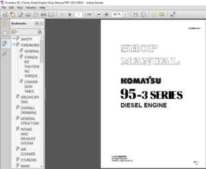
Foreword, Safety, Basic Information
How to Read the Engine Shop Manual
• Some of the attachments and options described in this shop manual may not be available in some areas. If
they are required, consult your Komatsu distributor.
• The materials and specifications are subject to change without notice.
• Shop manuals are available for “machine part” and “engine part”. For the engine unit, see the shop manual
for the machine which has the same engine model.
• Actual machine may differ from the images which are contained in this manual. A typical model is shown in
the illustrations of this shop manual.
Composition of the Shop Manual
This shop manual contains technical information necessary to perform services in workshops. It is divided into
the following chapters for the ease of use.
00 Index and Foreword
This section describes the index, foreword, safety, and basic information.
01 SpecificationS
This section describes the specifications of the machine.
10 Structure and Function
This section describes the structure and operation of each component with respect to each system. “Structure
and Function” is helpful in not only understanding the structure of each component but performing troubleshooting.
20 Standard Value Table
This section describes the standard values for new machine and failure criteria for testing and adjusting, and
troubleshooting. Use the standard values table to check the standard values for testing and adjusting, and judge
troubles in troubleshooting.
50 Disassembly and Assembly
This section describes the special tools, work procedures, and safety precautions necessary for removal, installation,
disassembly, and assembly of the components and parts. In addition, tightening torques, quantity, and
weight of the coating materials, lubricants, and coolant necessary to these works are shown.
60 Maintenance Standard
This section describes the maintenance standard value of each component. The maintenance standard shows
the criteria and remedies for disassembly and assembly.
TABLE OF CONTENTS:
Komatsu ENGINE 114E -6 SERIES Shop Manual SEN06506-11- PDF DOWNLOAD
Cover 1
00 Index and Foreword 3
Index 4
Abbreviation List 6
Foreword, Safety, Basic Information 12
How to Read the Engine Shop Manual 12
Safety Notice for Operation 14
Precautions to Prevent Fire 22
Procedures If Fire Occurs 24
Precautions When You Discard Waste Materials 25
Actions Taken to Meet Exhaust Gas Regulations 26
Precautions for DEF 27
General Character and Precautions for Handling 27
Precautions When You Add 27
Precautions for Storage 27
Precautions for Fire Hazard and Leakage 27
Other Precautions 27
Store DEF 28
Precautions When You Handle Hydraulic Equipment 29
Precautions When You Disconnect and Connect Pipings 32
Precautions When You Handle Electrical Equipment 39
Precautions When You Handle Fuel System Equipment 41
Precautions When You Handle Intake System Equipment 42
Disconnect and Connect Push-Pull Type Coupler 43
How to Disconnect and Connect Type 1 Push-Pull Type Coupler 43
How to Disconnect and Connect Type 2 Push-Pull Type Coupler 44
How to Disconnect and Connect Type 3 Push-Pull Type Coupler 45
Precautions for Disconnection and Connection of Connectors 47
Disconnect and Connect Deutsch Connector 51
How to Disconnect and Connect Slide Lock Type Connector 52
Disconnect and Connect Connector with Lock to Pull 54
Disconnect and Connect Connector with Lock to Push 55
Disconnect and Connect Connector with Housing to Rotate 57
How to Read the Codes for Electric Cable 58
Explanation of Terms for Maintenance Standard 62
Standard Tightening Torque Table 65
Conversion Table 72
01 Specification 77
Table of Contents 78
Abbreviation List 79
Specifications 85
Outline of Exhaust Gas Regulation 85
System Diagram of Engine Conformed to Tier4 Regulation 87
Improvement of Engine Conformed to Tier4 Regulation 88
List of Applicable Machines: 114E-6 89
Specifications 90
Specifications: SAA6D114E-6 (D65EX-18, D65EX-18E0, D65EX-18M0, D65EXI-18, D65EXI-18E0, D65PX-18, D65PX-18E0, D65PXI-18, D65PXI-18E0, D65WX-18, D65WX-18E0) 90
Specifications: SAA6D114E-6 (D71EX-24, D71EX-24E0, D71EXI-24, D71EXI-24E0, D71PX-24, D71PX-24E0, D71PXI-24, D71PXI-24E0) 91
Specifications: SAA6D114E-6 (HB365LC-3) 92
Specifications: SAA6D114E-6 (PC360LC-11, PC360LCI-11) 93
Engine General View 94
Engine General View: SAA6D114E-6 (D65EX-18, D65EX-18E0, D65EX-18M0, D65EXI-18, D65EXI-18E0, D65PX-18, D65PX-18E0, D65PXI-18, D65PXI-18E0, D65WX-18, D65WX-18E0) 94
Engine General View: SAA6D114E-6 (D71EX-24, D71EX-24E0, D71EXI-24, D71EXI-24E0, D71PX-24, D71PX-24E0, D71PXI-24, D71PXI-24E0) 98
Engine General View: SAA6D114E-6 (HB365LC-3)102
Engine General View: SAA6D114E-6 (PC360LC-11, PC360LCI-11)106
Engine Performance Curve110
Engine Performance Curve: SAA6D114E-6 (D65EX-18, D65EX-18E0, D65EX-18M0, D65EXI-18, D65EXI-18E0, D65PX-18, D65PX-18E0, D65PXI-18, D65PXI-18E0, D65WX-18, D65WX-18E0)110
Engine Performance Curve: SAA6D114E-6 (D71EX-24, D71EX-24E0, D71EXI-24, D71EXI-24E0, D71PX-24, D71PX-24E0, D71PXI-24, D71PXI-24E0)111
Engine Performance Curve: SAA6D114E-6 (HB365LC-3, PC360LC-11, PC360LCI-11)112
10 Structure and Function113
Table of Contents114
Abbreviation List116
Urea SCR System122
Layout Drawing of Urea SCR System122
Urea SCR System Diagram124
Function of Urea SCR System126
Function of DEF System126
Inducement Strategy129
Component Parts of Urea SCR System160
DEF Mixing Tube160
SCR Assembly161
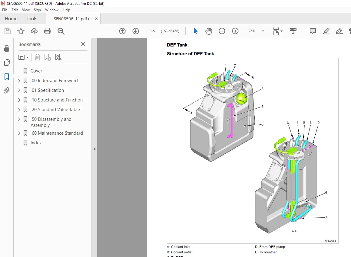
DEF Tank163
DEF Pump165
DEF Injector166
DEF Hose167
DEF Tank Heating Valve168
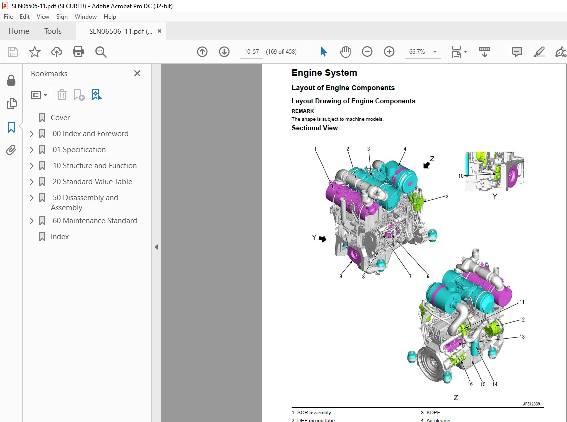
Engine System169
Layout of Engine Components169
Layout Drawing of Engine Components169
Intake and Exhaust System Parts171
Layout Drawing of Intake and Exhaust System171
Intake and Exhaust System Circuit Diagram172
Function of Intake and Exhaust System172
Air Cleaner174
Intake Air Heater176
Engine Main Body Parts177
Cylinder Head177
Cylinder Block179
Main Drive Parts181
Vibration Damper184
Timing Gear185
Front Cover186
Valve System187
Flywheel and Flywheel Housing188
Turbocharger System189
Circuit Diagram of VGT System189
Function of VGT System190
VGT191
EGR System195
EGR Valve197
EGR Cooler199
KCCV System201
KCCV Ventilator205
KDPF207
Lubrication System211
Layout Drawing of Lubrication System Parts211
Lubrication System Circuit Diagram212
Engine Oil Pump213
Engine Boost Oil Pump214
Engine Oil Filter215
Engine Oil Cooler216
Safety Valve of Engine Oil Filter217
Engine Oil Pan218
Fuel System219
Layout Drawing of Fuel System Parts219
Fuel System Circuit Diagram220
Function of Fuel System220
Supply Pump223
Fuel Prefilter226
Fuel Main Filter227
Cooling System228
Layout Drawing of Cooling System Parts228
Cooling System Circuit Diagram229
Drive Pulley231
Water Pump233
Thermostat234
Electrical System236
Component Parts of Electrical System236
Alternator236
Starting Motor239
Engine Wiring Harness242
Engine Controller244
Sensor251
Layout Drawing of Engine Sensor251
Structure of Ambient Pressure Sensor254
Function of Ambient Pressure Sensor254
Structure of Engine Oil Pressure Switch255
Function of Engine Oil Pressure Switch255
Structure of Charge (Boost) Pressure and Temperature Sensor256
Function of Charge (Boost) Pressure and Temperature Sensor256
Structure of Coolant Temperature Sensor257
Function of Coolant Temperature Sensor257
Structure of NE (Crankshaft) Speed Sensor258
Function of NE (Crankshaft) Speed Sensor258
Structure of Bkup (Camshaft) Speed Sensor259
Function of Bkup (Camshaft) Speed Sensor259
Structure of Common Rail Pressure Sensor260
Function of Common Rail Pressure Sensor260
Structure of EGR Valve Lift Sensor261
Function of EGR Valve Lift Sensor261
Structure of VGT Speed Sensor262
Function of VGT Speed Sensor262
Structure of VGT Position Sensor263
Function of VGT Position Sensor263
Structure of Mass Air Flow and Temperature Sensor264
Function of Mass Air Flow and Temperature Sensor264
Structure of KDPF Differential Pressure and Outlet Pressure Sensor265
Function of KDPF Differential Pressure and Outlet Pressure Sensor265
Structure of Crankcase Pressure Sensor266
Function of Crankcase Pressure Sensor266
Structure of Air Cleaner Clogging Sensor267
Function of Air Cleaner Clogging Sensor267
Structure of Water-in-Fuel Sensor268
Function of Water-in-Fuel Sensor268
20 Standard Value Table269
Table of Contents270
Abbreviation List271
Standard Value Table for Engine277
Standard Value Table for Engine: SAA6D114E-6 (D65EX-18, D65EX-18E0, D65EX-18M0, D65EXI-18, D65EXI-18E0, D65PX-18, D65PX-18E0, D65PXI-18, D65PXI-18E0, D65WX-18, D65WX-18E0)277
Standard Value Table for Engine: SAA6D114E-6 (D71EX-24, D71EX-24E0, D71EXI-24, D71EXI-24E0, D71PX-24, D71PX-24E0, D71PXI-24, D71PXI-24E0)281
Standard Value Table for Engine: SAA6D114E-6 (HB365LC-3)285
Standard Value Table for Engine: SAA6D114E-6 (PC360LC-11, PC360LCI-11)289
Running-in Standard and Performance Test Standard293
Running-in Standard and Performance Test Standard: SAA6D114E-6 (D65EX-18, D65EXI-18, D65PX-18, D65PXI-18, D65WX-18)293
Running-in Standard and Performance Test Standard: SAA6D114E-6 (D65EX-18E0, D65EX-18M0, D65EXI-18E0, D65PX-18E0, D65PXI-18E0, D65WX-18E0)295
Running-in Standard and Performance Test Standard: SAA6D114E-6 (D71EX-24, D71EX-24E0, D71EXI-24, D71EXI-24E0, D71PX-24, D71PX-24E0, D71PXI-24, D71PXI-24E0)297
Running-in Standard and Performance Test Standard: SAA6D114E-6 (HB365LC-3)299
Running-in Standard and Performance Test Standard: SAA6D114E-6 (PC360LC-11, PC360LCI-11)301
50 Disassembly and Assembly303
Table of Contents304
Abbreviation List305
Related Information on Disassembly and Assembly311
How to Read This Manual311
Coating Materials List312
Special Tool List317
Sketches of Special Tools319
Engine System320
Disassemble and Assemble Engine Generally320
Disassemble Engine Generally321
How to Assemble Engine Generally352
Remove and Install Supply Pump Assembly404
Remove Supply Pump Assembly404
Install Supply Pump Assembly406
Remove and Install Engine Front Oil Seal410
How to Remove Engine Front Oil Seal410
How to Install Engine Front Oil Seal411
Remove and Install Engine Rear Oil Seal414
How to Remove Engine Rear Oil Seal414
How to Install Engine Rear Oil Seal415
60 Maintenance Standard423
Table of Contents424
Abbreviation List425
Engine System431
Intake and Exhaust System Parts431
Maintenance Standard for VGT431
Engine Main Body Parts432
Maintenance Standard for Cylinder Head432
Maintenance Standard for Cylinder Block434
Maintenance Standard for Cylinder Liner436
Maintenance Standard for Crankshaft438
Maintenance Standard for Piston440
Maintenance Standard for Connecting Rod441
Maintenance Standard for Vibration Damper443
Maintenance Standard for Timing Gear444
Maintenance Standard for Camshaft445
Maintenance Standard for Valve and Valve Guide446
Maintenance Standard for Rocker Arm448
Maintenance Standard for Flywheel449
Lubrication System451
Maintenance Standard for Engine Oil Pump451
Index453
IMAGES PREVIEW OF THE MANUAL:
S.M 20/12/24