Komatsu ENGINE 12V140E-3 SERIES Shop Manual SEN00291-15 PDF
$31.95
Komatsu ENGINE 12V140E-3 SERIES Shop Manual SEN00291-15 – PDF DOWNLOAD
Description
Komatsu ENGINE 12V140E-3 SERIES Shop Manual SEN00291-15 – PDF DOWNLOAD
FILE DETAILS:
Komatsu ENGINE 12V140E-3 SERIES Shop Manual SEN00291-15 – PDF DOWNLOAD
Language : English
Pages : 602
Downloadable : Yes
File Type : PDF
IMAGES PREVIEW OF THE MANUAL:
TABLE OF CONTENTS:
Komatsu ENGINE 12V140E-3 SERIES Shop Manual SEN00291-15 – PDF DOWNLOAD
Cover 1
00 Index and foreword 0
Index 3
Composition of shop manual . 4
Table of contents 5
Foreword and general information . 13
Safety notice 14
How to read the shop manual 19
Explanation of terms for maintenance standard 21
Handling of electric equipment and hydraulic component . 23
Handling of connectors newly used for engines 32
How to read electric wire code . 35
Precautions when carrying out operation 38
Method of disassembling and connecting push-pull type coupler 41
Standard tightening torque table . 44
Conversion table . 48
01 Specification . 0
Specification and technical data . 55
Outline 56
Specifications . 58
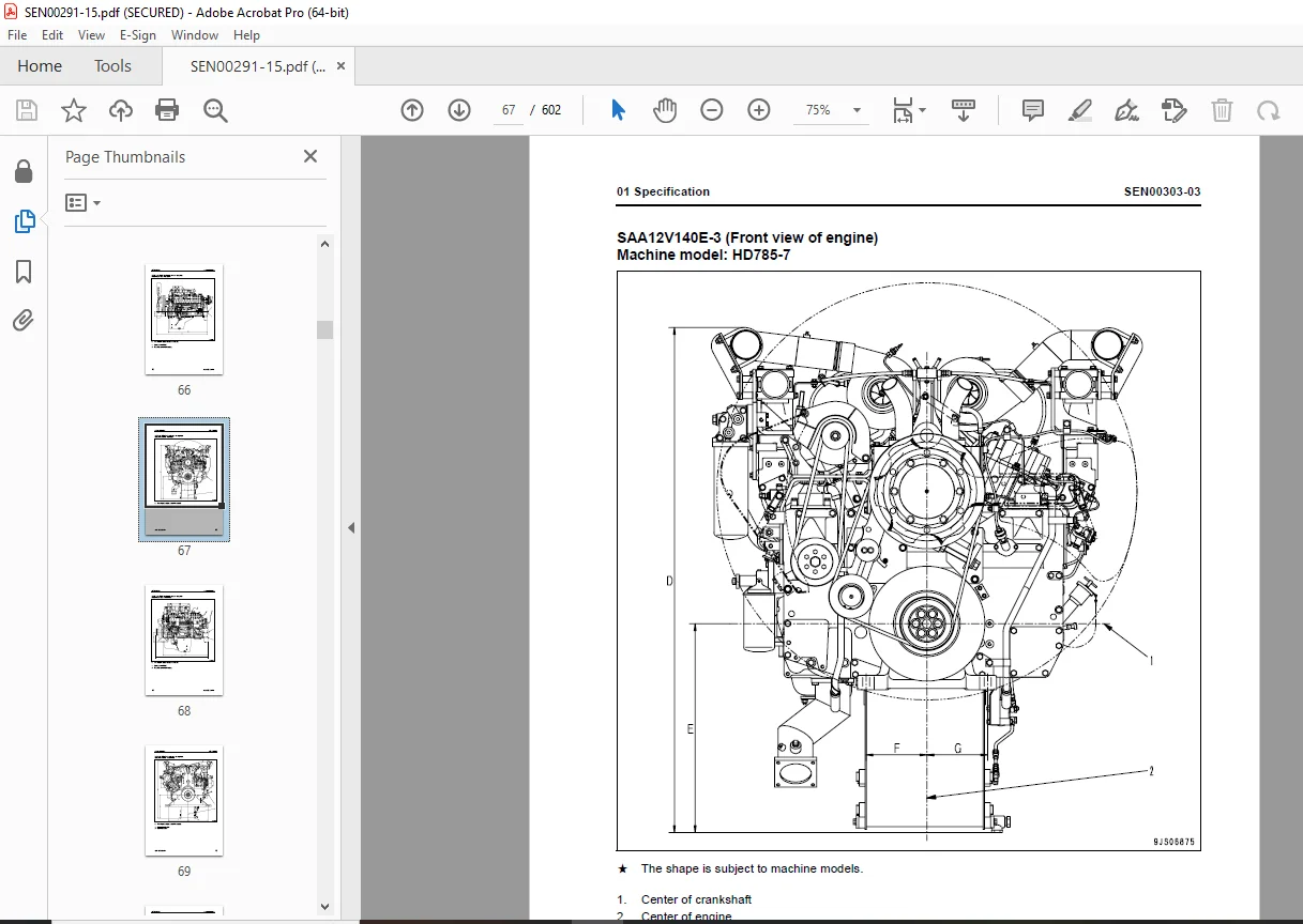
General view . 64
Weight table . 73
Engine performance curves 74
10 Structure, function and maintenance standard 0
Structure, function and maintenance standard, Part 1 . 81
Air intake and exhaust unit 83
Air cleaner 84
Turbocharger . 86
Aftercooler 91
Muffler 92
Cylinder head 94
Cylinder block . 98
Cylinder liner .102
Main moving parts 104
Crankshaft .106
Camshaft .108
Cam follower and push rod 109
Piston, piston ring, and piston pin 110
Connecting rod .112
Flywheel and flywheel housing 114
Vibration damper .115
Timing gear 116
Valve system .118
Valve and valve guide 120
Rocker arm and shaft .122
Crosshead and guide 123
Structure, function and maintenance standard, Part 2 .125
Lubrication system .128
Lubrication system diagram .128
Oil pump .130
Oil cooler .131
Oil filter .132
Main relief valve 133
Oil cooler bypass valve and regulator valve 134
Fuel system 136
CRI system diagram .136
CRI system diagram (Poor fuel spec.) .138
Outline of CRI system 140
Fuel piping 158
Fuel piping (Poor fuel spec.) 163
Fuel filter 168
Water separator 170
Priming pump .171
Electric priming pump 172
Cooling system .174
Cooling system diagram .174
Water pump .176
Thermostat .178
Corrosion resistor .179
Cooling fan drive 181
Electrical equipment .184
Alternator .184
Starting motor .186
Starting aid .188
Engine controller 191
Engine controller cooler .192
20 Standard value table 0
Standard service value table .195
Standard service value table .196
Standard service value table for testing, adjusting, and troubleshooting .196
Running-in standard and performance test standard 201
30 Testing and adjusting . 0
Testing and adjusting 207
Testing and adjusting tools list .209
Testing air boost pressure .211
Testing exhaust temperature 212
Adjusting valve clearance 213
Testing compression pressure .215
Testing blow-by pressure .217
Testing oil pressure .218
Handling fuel system parts .219
Releasing residual pressure in fuel system .219
Testing fuel pressure 220
Reduced cylinder mode operation 221
No-injection cranking 221
Testing leakage-from pressure limiter and return rate from injector 222
Bleeding air from fuel circuit (for D475A-5) .225
Bleeding air from fuel circuit (for PC2000) 228
Bleeding air from fuel circuit (Poor fuel spec.) .230
Testing fuel system for leakage 232
Adjusting speed sensor .233
Testing and adjusting alternator belt tension 233
Handling controller high-voltage circuit .234
40 Troubleshooting . 0
General Information on troubleshooting .237
Points to remember when troubleshooting 238
Error codes and failure codes list .239
Information in troubleshooting table .243
Connection table for connector pin numbers .245
T- branch box and T- branch adapter table 281
Troubleshooting of mechanical system (S-mode) 285
Method of using troubleshooting charts .287
S-1 Starting performance is poor .290
S-2 Engine does not start 291
S-3 Engine does not pick up smoothly .294
S-4 Engine stops during operations .295
S-5 Engine does not rotate smoothly 296
S-6 Engine lacks output (or lacks power) .297
S-7 Exhaust smoke is black (incomplete combustion) .299
S-8 Oil consumption is excessive (or exhaust smoke is blue) 300
S-9 Oil becomes contaminated quickly .301
S-10 Fuel consumption is excessive .302
S-11 Oil is in coolant (or coolant spurts back or coolant level goes down) .303
S-12 Oil pressure drops 304
S-13 Oil level rises (Entry of coolant or fuel) 305
S-14 Coolant temperature becomes too high (overheating) 306
S-15 Abnormal noise is made 307
S-16 Vibration is excessive 308
Troubleshooting of electrical system (E-mode), Part 1 311
E-1 Code [111/CA111] ECM Critical Internal Failure (LH bank) .314
E-2 Code [111/CB111] ECM Critical Internal Failure (RH bank) .316
E-3 Code [115/CA115] Eng. Ne and G (Bkup) Speed Sensor Error (LH bank) .318
E-4 Code [115/CB115] Eng. Ne and G (Bkup) Speed Sensor Error (RH bank) .319
E-5 Code [122/CA122] Charge Air Press. Sensor High Error (LH bank only) 320
E-6 Code [123/CA123] Charge Air Press. Sensor Low Error (LH bank only) .322
E-7 Code [131/CA131] Throttle Sensor High Error (LH bank only) .324
E-8 Code [132/CA132] Throttle Sensor Low Error (LH bank only) 325
E-9 Code [135/CA135] Oil Press. Sensor High Error (LH bank only) .326
E-10 Code [141/CA141] Oil Press. Sensor Low Error (LH bank only) .328
E-11 Code [144/CA144] Coolant Temp. Sensor High Error (LH bank only) .330
E-12 Code [145/CA145] Coolant Temp. Sensor Low Error (LH bank only) 332
E-13 Code [153/CA153] Charge Air Temp. Sensor High Error (LH bank only) 334
E-14 Code [154/CA154] Charge Air Temp. Sensor Low Error (LH bank only) .336
E-15 Code [187/CA187] Sensor Sup. 2 Volt. Low Error (LH bank) 337
E-16 Code [187/CB187] Sensor Sup. 2 Volt. Low Error (RH bank) 337
E-17 Code [212/CA212] Eng. Oil Temp.Sensor High Error (LH bank only) .338
E-18 Code [213/CA213] Eng. Oil Temp.Sensor Low Error (LH bank only) 340
E-19 Code [221/CA221] Ambient Air Press. Sensor High Error (LH bank only) 342
E-20 Code [222/CA222] Ambient Air Press. Sensor Low Error (LH bank only) .344
E-21 Code [227/CA227] Sensor Sup. 2 Volt. High Error (LH bank) .346
E-22 Code [227/CB227] Sensor Sup. 2 Volt. High Error (RH bank) .348
E-23 Code [234/CA234] Eng. Overspeed (LH bank only) 350
E-24 Code [238/CA238] Ne Speed Sensor Sup. Volt. Error (LH bank) .352
E-25 Code [238/CB238] Ne Speed Sensor Sup. Volt. Error (RH bank) .354
E-26 Code [263/CA263] Fuel Temp. Sensor High Error (LH bank) .356
E-27 Code [263/CB263] Fuel Temp. Sensor High Error (RH bank) .358
E-28 Code [265/CA265] Fuel Temp. Sensor Low Error (LH bank) 360
E-29 Code [265/CB265] Fuel Temp. Sensor Low Error (RH bank) 360
E-30 Code [271/CA271] PCV1 Short Error (LH bank) .362
E-31 Code [271/CB271] PCV1 Short Error (RH bank) .364
E-32 Code [272/CA272] PCV1 Open Error (LH bank) 366
E-33 Code [272/CB272] PCV1 Open Error (RH bank) 367
E-34 Code [273/CA273] PCV2 Short Error (LH bank) .368
E-35 Code [273/CB273] PCV2 Short Error (RH bank) .370
E-36 Code [274/CA274] PCV2 Open Error (LH bank) 372
E-37 Code [274/CB274] PCV2 Open Error (RH bank) 373
E-38 Code [322/CA322] Injector #1 (L/B #1) System Open/Short Error (LH bank) .374
E-39 Code [323/CA323] Injector #5 (L/B #5) System Open/Short Error (LH bank) .376
E-40 Code [324/CA324] Injector #3 (L/B #3) System Open/Short Error (LH bank) .378
E-41 Code [325/CA325] Injector #6 (L/B #6) System Open/Short Error (LH bank) .380
E-42 Code [331/CA331] Injector #2 (L/B #2) System Open/Short Error (LH bank) .382
E-43 Code [332/CA332] Injector #4 (L/B #4) System Open/Short Error (LH bank) .384
E-44 Code [342/CA342] Caribration Code Incompatibility (LH bank) .386
E-45 Code [342/CB342] Caribration Code Incompatibility (RH bank) .386
E-46 Code [351/CA351] INJ. Drive Circuit Error (LH bank) .388
E-47 Code [351/CB351] INJ. Drive Circuit Error (RH bank) .390
E-48 Code [352/CA352] Sensor Sup. 1 Volt. Low Error (LH bank) 392
E-49 Code [352/CB352] Sensor Sup. 1 Volt. Low Error (RH bank) 392
E-50 Code [386/CA386] Sensor Sup. 1 Volt. High Error (LH bank) .394
E-51 Code [386/CB386] Sensor Sup. 1 Volt. High Error (RH bank) .396
E-52 Code [441/CA441] Battery Voltage Low Error (LH bank) 398
E-53 Code [441/CB441] Battery Voltage Low Error (RH bank) 398
E-54 Code [442/CA442] Battery Voltage High Error (LH bank) .399
E-55 Code [442/CB442] Battery Voltage High Error (RH bank) .399
Troubleshooting of electrical system (E-mode), Part 2 401
E-56 Code [449/CA449] Rail Press. Very High Error (LH bank) 403
E-57 Code [449/CB449] Rail Press. Very High Error (RH bank) 403
E-58 Code [451/CA451] Rail Press. Sensor High Error (LH bank) 404
E-59 Code [451/CB451] Rail Press. Sensor High Error (RH bank) 406
E-60 Code [452/CA452] Rail Press. Sensor Low Error (LH bank) .408
E-61 Code [452/CB452] Rail Press. Sensor Low Error (RH bank) .408
E-62 Code [553/CA553] Rail Press. High Error 1 (LH bank) .409
E-63 Code [553/CB553] Rail Press. High Error 1 (RH bank) .410
E-64 Code [554/CA554] Rail Press. Sensor In Range Error (LH bank) 411
E-65 Code [554/CB554] Rail Press. Sensor In Range Error (RH bank) 411
E-66 Code [559/CA559] Rail Press. Low Error 1 (LH bank) 412
E-67 Code [559/CB559] Rail Press. Low Error 1 (RH bank) 416
E-68 Code [689/CA689] Eng. Ne Speed Sensor Error (LH bank) .420
E-69 Code [689/CB689] Eng. Ne Speed Sensor Error (RH bank) .422
E-70 Code [691/CA691] Intake Air Temp Sensor High Error (LH bank only) .424
E-71 Code [692/CA692] Intake Air Temp Sensor Low Error (LH bank only) 426
E-72 Code [731/CA731] Eng. G (Bkup) Speed Sensor Phase Error (LH bank) .427
E-73 Code [731/CB731] Eng. G (Bkup) Speed Sensor Phase Error (RH bank) .427
E-74 Code [757/CA757] All Continuous Data Lost Error (LH bank) .428
E-75 Code [757/CB757] All Continuous Data Lost Error (RH bank) .428
E-76 Code [778/CA778] Eng. G (Bkup) Speed Sensor Error (LH bank) .430
E-77 Code [778/CB778] Eng. G (Bkup) Speed Sensor Error (RH bank) .432
E-78 Code [781/CA781] Inter Multi-controller Communication Error (LH bank) .434
E-79 Code [781/CB781] Inter Multi-controller Communication Error (RH bank) .436
E-80 Code [1117/CA1117] Persistent Data Lost Error (LH bank) .437
E-81 Code [1117/CB1117] Persistent Data Lost Error (RH bank) .437
E-82 Code [1257/CA1257] Harness Key error (LH bank) 438
E-83 Code [1257/CB1257] Harness Key error (RH bank) 439
E-84 Code [1548/CB1548] Injector #7 (R/B #1) System Open/Short Error (RH bank) .440
E-85 Code [1549/CB1549] Injector #8 (R/B #2) System Open/Short Error (RH bank) .442
E-86 Code [1551/CB1551] Injector #10 (R/B #4) System Open/Short Error (RH bank) 444
E-87 Code [1552/CB1552] Injector #11 (R/B #5) System Open/Short Error (RH bank) 446
E-88 Code [1553/CB1553] Injector #12 (R/B #6) System Open/Short Error (RH bank) 448
E-89 Code [1622/CB1622] Injector #9 (R/B #3) System Open/Short Error (RH bank) .450
E-90 Code [1633/CA1633] KOMNET Datalink Timeout Error (LH bank) 452
E-91 Code [2185/CA2185] Throttle Sens. Sup. Volt. High Error (LH bank only) 454
E-92 Code [2186/CA2186] Throttle Sens. Sup. Volt. Low Error (LH bank only) .456
E-93 Code [2249/CA2249] Rail Press. Very Low Error (LH bank) .457
E-94 Code [2249/CB2249] Rail Press. Very Low Error (RH bank) .457
E-95 Code [- -*1/-] Eng. Overheat (LH bank only) .458
E-96 Code [- -*2/-] Eng. Oil Press. Low Speed Derate (LH bank only) 458
E-97 Code [- -*3/-] Press. Low Torque Derate (LH bank only) 459
50 Disassembly and assembly 0
General information on disassembly and assembly 461
How to read this manual 462
Coating materials list .464
Special tool list 467
Sketches of special tools 469
Disassembly and assembly, Part 1 .473
Disassembly and assembly, Part 1 .474
General disassembly of engine 474
Disassembly and assembly, Part 2 .493
General assembly of engine .494
Disassembly and assembly, Part 3 .533
Removal and installation fuel supply pump unit .534
Removal and installation oil seal unit .537
90 Repair and replacement of parts . 0
Information related to repair and replacement 545
Flowchart .546
Special tool table .548
Parts related to cylinder head .551
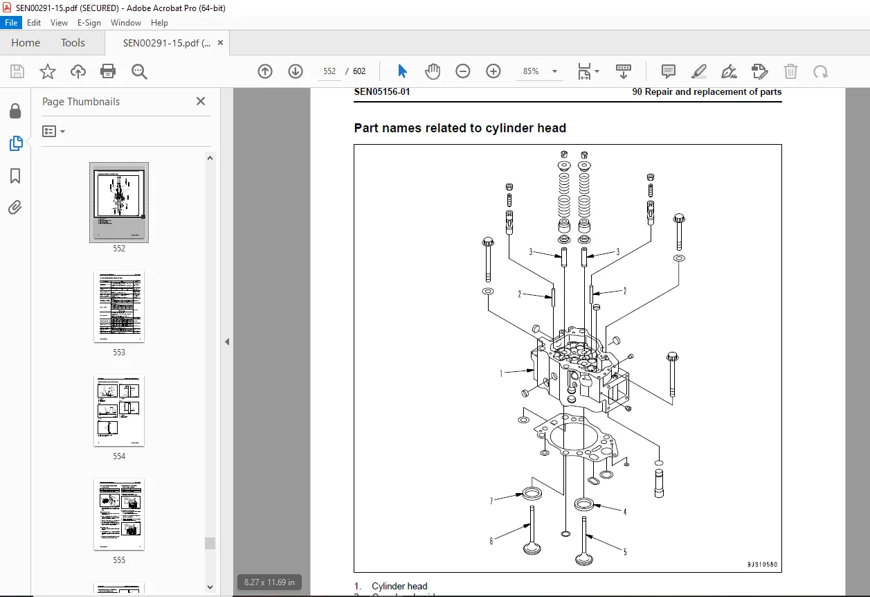
Part names related to cylinder head 552
Testing and inspection of cylinder head 553
Pressure test of cylinder head .555
Replacement of valve guide .555
Replacement of valve seat insert .556
Replacement of crosshead guide .563
Repair of cylinder head mounting face by grinding 564
Repair of valve by grinding 565
Parts related to cylinder block 567
Part names related to cylinder block .569
Testing and inspection of cylinder block .570
Part names related to crankshaft .573
Testing and inspection of crankshaft .574
Part names related to connecting rod .575
Testing and inspection of connecting rod .576
Replacement of flywheel ring gear 577
Replacement of crankshaft gear .578
Replacement of camshaft gear .579
Replacement of main bearing metal cap 580
Replacement of connecting rod small end bushing 582
Replacement of cam bushing .583
Repair of cylinder block top by grinding .585
Repair of counterbore by grinding 586
Check and identification after repair by grinding 588
Gasket sealant application procedure .589
Repair standard for cylinder liner O-ring 591
Repair of crankshaft by grinding .592
Improvement of surface roughness of crankshaft journal .598
DESCRIPTION:
Komatsu ENGINE 12V140E-3 SERIES Shop Manual SEN00291-15 – PDF DOWNLOAD
This shop manual contains the necessary technical information for services performed in a workshop.
For ease of understanding, the manual is divided into the following sections.
00. Index and foreword
This section explains the shop manuals list, table of contents, safety, and basic information.
01. Specification
This section explains the specifications of the machine.
10. Structure, function and maintenance standard
This section explains the structure, function, and maintenance standard values of each component.
The structure and function sub-section explains the structure and function of each component. It
serves not only to give an understanding of the structure, but also serves as reference material for
troubleshooting. The maintenance standard sub-section explains the criteria and remedies for disassembly
and service.
20. Standard value table
This section explains the standard values for new machine and judgement criteria for testing,
adjusting, and troubleshooting. This standard value table is used to check the standard values in
testing and adjusting and to judge parts in troubleshooting.
30. Testing and adjusting
This section explains measuring instruments and measuring methods for testing and adjusting, and
method of adjusting each part. The standard values and judgement criteria for testing and adjusting
are explained in Testing and adjusting.
40. Troubleshooting
This section explains how to find out failed parts and how to repair them. The troubleshooting is
divided by failure modes. The S mode of the troubleshooting related to the engine may be also
explained in the Chassis volume and Engine volume. In this case, see the Chassis volume.
50. Disassembly and assembly
This section explains the special tools and procedures for removing, installing, disassembling, and
assembling each component, as well as precautions for them. In addition, tightening torque and
quantity and weight of coating material, oil, grease, and coolant necessary for the work are also
explained.
90. Diagrams and drawings (chassis volume)/Repair and replacement of parts (engine volume)
q Chassis volume
This section gives hydraulic circuit diagrams and electrical circuit diagrams.
q Engine volume
This section explains the method of reproducing, repairing, and replacing parts.
2. Revision and distribution
Any additions, revisions, or other change of notices will be sent to KOMATSU distributors. Get the most
up-to-date information before you start any work
G.B 25/12/24


