
Trusted Business
Verified & Licensed
Virus Free Files
100% Safe Downloads
Secure Payment
SSL Protected
Instant Delivery
Available Immediately
Sale!


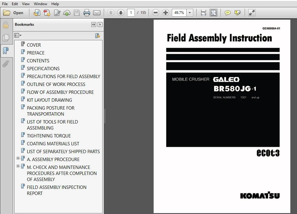
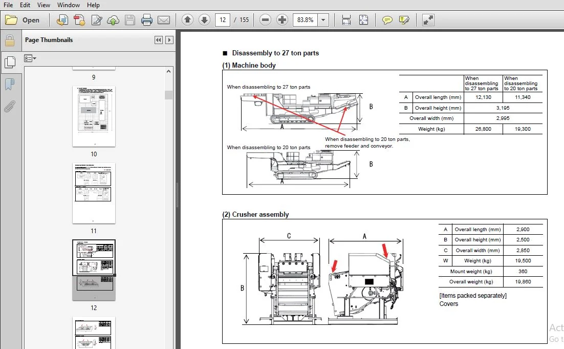
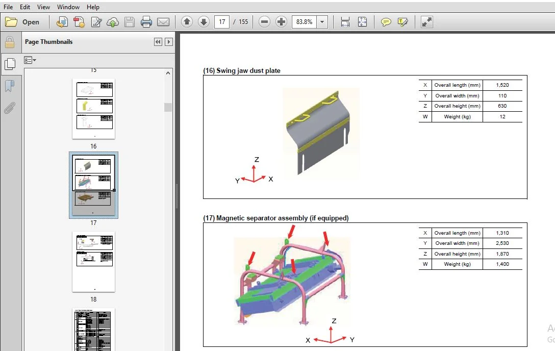
KOMATSU GALEO BR580JG MOBILE CRUSHER FIELD ASSEMBLY INSTRUCTION MANUAL (SN:1001 & UP) KOMATSU GALEO BR580JG – PDF DOWNLOAD
Original price was: $58.95.$24.95Current price is: $24.95.
- KOMATSU GALEO BR580JG MOBILE CRUSHER FIELD ASSEMBLY INSTRUCTION MANUAL
- SERIAL NUMBER:1001 & UP
- PUBLICATION NUMBER:GEN00064-01
Instant PDF Download
Available immediately
Save to Your Device
Download & keep forever
Antivirus Scanned
100% virus-free
Trusted Worldwide
175,000+ customers
Description
KOMATSU GALEO BR580JG MOBILE CRUSHER FIELD ASSEMBLY INSTRUCTION MANUAL (SN:1001 & UP) KOMATSU GALEO BR580JG
KOMATSU GALEO BR580JG MOBILE CRUSHER FIELD ASSEMBLY INSTRUCTION MANUAL (SN:1001 & UP) KOMATSU GALEO BR580JG – PDF DOWNLOAD:
IMAGE PREVIEW:
DESCRIPTION:
KOMATSU GALEO BR580JG MOBILE CRUSHER FIELD ASSEMBLY INSTRUCTION MANUAL (SN:1001 & UP) KOMATSU GALEO BR580JG
- You are required to execute full inspection and maintenance before starting the engine and assembling the work equipment. Since the work is often carried out in dangerous places and positions by a team, hold a safety meeting in advance and appoint a crane director, work leader, etc.
- so that the all members can work safely. When the work is carried out in an overseas country, difference in language, customs, etc. lowers safety. Accordingly, the field liaison man and work supervisor must examine the above point and take necessary measures.
- We hope that the all members will cooperate with each other and assemble the work equipment quickly in the field, observing the safety, quality, and delivery time.
TABLE OF CONTENTS:
KOMATSU GALEO BR580JG MOBILE CRUSHER FIELD ASSEMBLY INSTRUCTION MANUAL (SN:1001 & UP) KOMATSU GALEO BR580JG
COVER.........................................................................  1
PREFACE.......................................................................  2
CONTENTS......................................................................  3
SPECIFICATIONS................................................................  6
PRECAUTIONS FOR FIELD ASSEMBLY................................................  7
OUTLINE OF WORK PROCESS.......................................................  8
FLOW OF ASSEMBLY PROCEDURE....................................................  9
KIT LAYOUT DRAWING............................................................ 10
PACKING POSTURE FOR TRANSPORTATION............................................ 11
LIST OF TOOLS FOR FIELD ASSEMBLING............................................ 19
TIGHTENING TORQUE............................................................. 20
COATING MATERIALS LIST........................................................ 24
LIST OF SEPARATELY SHIPPED PARTS.............................................. 26
A. ASSEMBLY PROCEDURE......................................................... 34
	A- 1. PREPARATION FOR INSTALLATION OF CRUSHER ASSEMBLY.................... 35
	A- 2. INSTALLATION OF CRUSHER ASSEMBLY.................................... 40
	A- 3. INSTALLATION OF STEPS............................................... 42
	A- 4. INSTALLATION OF HANDRAILS........................................... 43
	A- 5. INSTALLATION OF FLOOR............................................... 45
	A- 6. INSTALLATION OF CRUSHER MOTOR HOSES................................. 46
	A- 7. INSTALLATION OF LOCK CYLINDER HOSES................................. 47
	A- 8. INSTALLATION OF CRUSHER WIRING...................................... 49
	A- 9. INSTALLATION OF CRUSHER COVERS...................................... 50
	A-10. INSTALLATION OF GUARD ASSEMBLY...................................... 54
	A-11. INSTALLATION OF DUST PLATE ASSEMBLY................................. 55
	A-12. INSTALLATION OF SECOND CHUTES....................................... 56
	A-13. INSTALLATION OF FEEDER MOTOR........................................ 59
	A-14. POSTURE OF OPEN/CLOSE HOPPER........................................ 61
	A-15. INSTALLATION OF HOPPER (R.H.) ...................................... 72
	A-16. INSTALLATION OF HOPPER (L.H.) ...................................... 76
	A-17. INSTALLATION OF HOPPER (REAR)....................................... 80
	A-18. INSTALLATION OF HOPPER PINS......................................... 85
	A-19. TIGHTENING OF HOPPER MOUNTING BOLTS................................. 87
	A-20. GREASING OF HOPPER.................................................. 89
	A-21. INSTALLATION OF FIXED HOPPER (IF EQUIPPED).......................... 90
	A-22. INSTALLATION OF CONVEYOR............................................ 91
	A-23. INSTALLATION OF CONVEYOR PIPING .................................... 98
	A-24. POSTURE OF CONVEYOR................................................. 99
	A-25. ADJUSTMENT OF CONVEYOR TENSION......................................105
	A-26. ADJUSTMENT OF CONVEYOR SNAKING......................................106
	A-27. ADJUSTMENT OF CONVEYOR SCRAPER......................................107
	A-28. ADJUSTMENT OF INSTALLATION OF RETURN ROLLER GUARD...................109
	A-29. ADJUSTMENT OF MUCK DISCHARGE CONVEYOR SCRAPER (IF EQUIPPED).........110
	A-30. INSTALLATION OF MAGNETIC SEPARATOR ASSEMBLY ........................111
	A-31. INSTALLATION OF REAR COVER FLOOR....................................113
	A-32. INSTALLATION OF TAIL PIPE ..........................................114
	A-33. INSTALLATION OF ROTARY LAMP AND WORKING LAMP ASSEMBLY ..............115
	A-34. INSTALLATION OF ROTARY LAMP AND WORKING LAMP WIRING.................116
	A-35. ADJUSTMENT OF MIRRORS ..............................................117
	A-36. INSTALLATION OF RESERVOIR TANK COVER................................118
	A-37. INSTALLATION OF FUEL TANK COVER.....................................119
M. CHECK AND MAINTENANCE PROCEDURES AFTER COMPLETION OF ASSEMBLY .............120
	M-1. CHECK FUEL, COOLANT AND LUBRICANTS...................................121
	M-2. AIR BLEEDING FROM HYDRAULIC CIRCUITS.................................124
	M-3. REPLACEMENT OF RETURN FILTER (STANDARD FILTER TO FLUSHING FILTER)....127
	M-4. FLUSHING OF HYDRAULIC CIRCUIT........................................130
FIELD ASSEMBLY INSPECTION REPORT..............................................132
PLEASE NOTE:
⦁ This is the same manual used by the dealers to diagnose and troubleshoot your vehicle
⦁ You will be directed to the download page as soon as the purchase is completed. The whole payment and downloading process will take anywhere between 2-5 minutes
⦁ Need any other service / repair / parts manual, please feel free to contact [email protected] . We still have 50,000 manuals unlisted



