
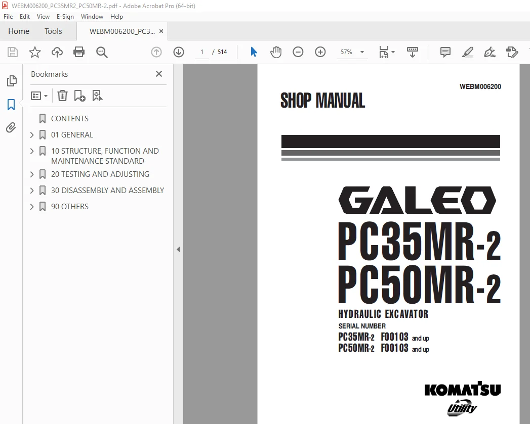
Komatsu Galeo PC35MR-2 PC50MR-2 Hydraulic Excavator Shop Manual WEBM006200 PDF
$30.95
Komatsu Galeo PC35MR-2 PC50MR-2 Hydraulic Excavator Shop Manual WEBM006200 – PDF DOWNLOAD
SERIAL NUMBER
PC35MR-2 F00103 and up
PC50MR-2 F00103 and up
Description
Komatsu Galeo PC35MR-2 PC50MR-2 Hydraulic Excavator Shop Manual WEBM006200 – PDF DOWNLOAD
FILE DETAILS:
Komatsu Galeo PC35MR-2 PC50MR-2 Hydraulic Excavator Shop Manual WEBM006200 – PDF DOWNLOAD
Language : English
Pages : 514
Downloadable : Yes
File Type : PDF
TABLE OF CONTENTS:
Komatsu Galeo PC35MR-2 PC50MR-2 Hydraulic Excavator Shop Manual WEBM006200 – PDF DOWNLOAD
SERIAL NUMBER
PC35MR-2 F00103 and up
PC50MR-2 F00103 and up
CONTENTS 4
01 GENERAL 29
Specification dimension drawing 30
Working range drawing 31
Specifications 32
Weight table 38
Lubricants, fuel and coolant specifications 40
10 STRUCTURE, FUNCTION AND MAINTENANCE STANDARD 43
PTO 44
Cooling system 45
Power train 47
Swing circle 48
Swing machinery 49
Track frame 53
Idler cushion 54
Idler 55
Track roller 57
Carrier roller 59
Sprocket 60
Track shoe 61
Hydraulic components layout drawing 68
Hydraulic tank 70
Center swivel joint 73
Travel motor 75
Hydraulic cylinder 83
Solenoid valve 87
Solenoid valve 88
Hydraulic pump 89
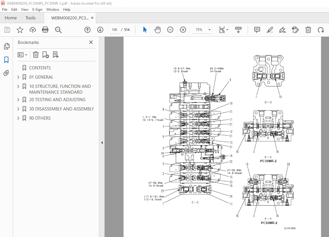
Control valve 101
Clss 117
Operation for each function and valve 120
Swing motor 142
PPC valve 151
Work equipment 159
Dimensions of each part of work equipment 162
Floor 166
Air conditioner 167
Engine control 168
Electric control system 170
Component parts of system 175
Monitor system 176
Monitor panel 177
Sensors 179
20 TESTING AND ADJUSTING 181
Standard value table for engine related parts 182
Standard value table for chassis related parts 184
TESTING AND ADJUSTING 199
List of testing, adjusting, and troubleshooting tools 200
Measuring engine speed 202
Measurement of exhaust gas color 203
Adjusting valve clearance 204
Measuring compression pressure 207
Measuring engine oil pressure 208
Testing and adjusting fuel injection timing 209
Testing and adjusting air conditioner compressor belt tension 212
Testing and adjusting alternator belt tension 213
Adjusting fuel control lever 214
Testing wear of sprocket 215
Testing and adjusting track shoe tension 216
Measurement of clearance in swing circle bearings 217
Measuring and adjusting oil pressures in work equipment, travel, boom swing, swing, and blade circuits 218
Measuring and adjusting LS differential pressure 224
Adjusting PC valve 228
Measuring and adjusting control pump circuit oil pressure 229
Measuring solenoid valve output pressure 231
Measuring PPC valve output pressure 233
Adjusting PPC valve 236
Measuring swing holding brake release pressure 237
Testing and adjusting travel deviation 238
Measurement of oil leakage from work equipment cylinder 240
Bleeding air from each part 242
Releasing residual pressure from hydraulic circuit 245
Releasing residual pressure from hydraulic tank 245
Pressurizing hydraulic tank 246
Inspection procedures for diode 247
TROUBLESHOOTING 249
Points to remember when troubleshooting 250
Sequence of events in troubleshooting 251
Points to remember when carrying out maintenance 252
Checks before troubleshooting 260
Classification and procedures of troubleshooting 261
Types and locations of connectors 264
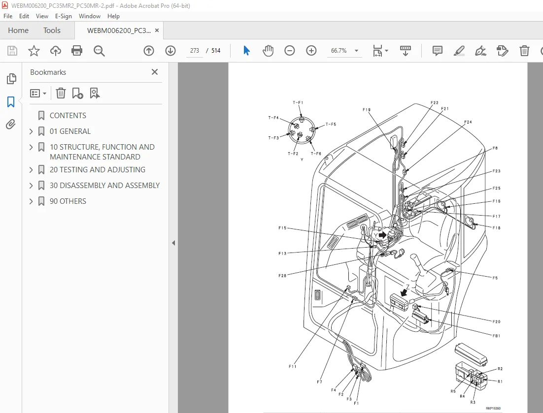
Connector arrangement diagram 270
Connection table for connector pin numbers 278
T-adapter – boxes and t-adapter table 300
TROUBLESHOOTING OF ELECTRICAL SYSTEM (E-MODE) 303
Before starting E-mode troubleshooting 304
Information contained in troubleshooting table 305
E-1 Engine does not start 306
E-2 Engine does not stop 314
E-3 When work equipment lock (PPC basic pressure lock) lever is set in LOCK position, work equipment still moves 318
E-4 Windshield wiper does not operate 322
E-5 Windshield washer does not operate 324
E-6 Travel alarm does not sound 328
E-7 heater does not operate 330
TROUBLESHOOTING OF HYDRAULIC AND MECHANICAL SYSTEM (H-MODE) 333
Information contained in troubleshooting table 334
H-1 Speed or power of whole work equipment, travel, swing, and blade is low 335
H-2 Engine speed lowers extremely or engine stalls 339
H-3 Whole work equipment, travel system, swing system, and blade do not work 340
H-4 Abnormal sound comes out from around hydraulic pump 344
H-5 Fine control performance or response is low 344
H-6 Speed or power of boom is low 345
H-7 Speed or power of arm is low 346
H-8 Speed or power of bucket is low 347
H-9 Speed or power of boom swing is low 348
H-10 Work equipment does not move singly 348
H-11 Work equipment hydraulic drift is lARge 349
H-12 Time lag of work equipment is large 350
H-13 In compound operation of work equipment, speed of part loaded more is low 350
H-14 Machine deviates during travel 351
H-15 Travel speed or travel power is low (while work equipment is normal) 353
H-16 Machine is not steered well or steering power is low 354
H-17 Travel speed does not change 355
H-18 Travel motor does not work 356
H-19 Speed or power of swing is low 358
H-20 Machine does not swing 360
H-21 Swing acceleration performance is low 362
H-22 Machine overruns when it stops swinging 364
H-23 Large shock is made when machine stops swinging 365
H-24 When upper structure stops swinging, it makes large sound 365
H-25 Hydraulic drift of swing is large 366
H-26 Speed or power of blade is low 367
H-27 Blade does not move 368
H-28 Hydraulic drift of blade is large 368
TROUBLESHOOTING OF MONITOR PANEL SYSTEM (M-MODE) 369
Before starting M-mode troubleshooting 370
Information contained in troubleshooting table 371
System diagram related to monitor panel 372
M-1 When starting switch is turned ON, any item does not operate 374
M-2 When starting switch is turned ON, some items do not operate 376
M-3 Alarm buzzer is abnormal 377
M-4 Engine oil pressure caution is turned ON 379
M-5 Charge level caution is turned ON 380
M-6 Preheating system does not operate or preheater does not become hot 384
M-7 Coolant temperature gauge is abnormal 386
M-8 Fuel level gauge is abnormal 391
M-9 Service meter does not operate while engine is running 395
M-10 2nd travel speed is not selected 397
M-11 Working lamp does not light up 402
TROUBLESHOOTING OF ENGINE (S-MODE) 405
Method of using troubleshooting charts 406
S-1 Starting performance is poor (Starting always takes time) 410
S-2 Engine does not start 412
S-3 Engine does not pick up smoothly (Follow-up is poor) 415
S-4 Engine stops during operations 416
S-5 Engine does not rotate smoothly (Hunting) 417
S-6 Engine lacks output or lacks power 418
S-7 Exhaust smoke is black (Incomplete combustion) 419
S-8 Oil consumption is excessive or exhaust smoke is blue 420
S-9 Oil becomes contaminated quickly 421
S-10 Fuel consumption is excessive 422
S-11 Oil is in cooling water, or water spurts back, or water level goes down 423
S-12 Oil pressure caution lamp lights up (Drop in oil pressure) 424
S-13 Oil level rises (Water, fuel in oil) 425
S-14 Water temperature becomes too high (Overheating) 426
S-15 Abnormal noise is made 427
S-16 Vibration is excessive 428
30 DISASSEMBLY AND ASSEMBLY 429
How to read this manual 430
Precautions when performing operation 432
Special tool list 434
sketches of special tools 438
Removal and installation of fuel injection pump assembly 439
Removal and installation of radiator and hydraulic oil cooler assembly 441
Removal and installation of engine and hydraulic pump assembly 450
Removal and installation of track shoe assembly 457
disassembly and assembly of idler assembly 458
Disassembly and assembly of recoil spring assembly 460
Disassembly and assembly of track roller assembly 463
Disassembly and assembly of carrier roller assembly 465
Removal and installation of center swivel joint assembly 466
Disassembly and assembly of center swivel joint assembly 469
Removal and installation of floor frame assembly 471
Removal and installation of swing motor and swing machinery assembly 475
Disassembly and assembly of swing motor and swing machinery assembly 476
Removal and installation of work equipment assembly 482
Removal and installation of revolving frame assembly 484
Removal and installation of swing circle assembly 486
Disassembly and assembly of control valve assembly 487
Disassembly and assembly of hydraulic cylinder assembly 488
Removal and installation of operator’s cab glass (stuck glass) 492
Removal and installation of front window assembly 500
90 OTHERS 501
Hydraulic circuit diagram (PC35MR-2) 503
Hydraulic circuit diagram (PC50MR-2) 505
Hydraulic circuit diagram PC50MR-2 (Additional attachment circuit) 507
Electrical circuit diagram PC35MR-2 509
Electrical circuit diagram PC50MR-2 511
DESCRIPTION:
Komatsu Galeo PC35MR-2 PC50MR-2 Hydraulic Excavator Shop Manual WEBM006200 – PDF DOWNLOAD
SERIAL NUMBER
PC35MR-2 F00103 and up
PC50MR-2 F00103 and up
GENERAL PRECAUTIONS :
Mistakes in operation are extremely dangerous. Read the OPERATION & MAINTENANCE MANUAL carefully BEFORE operating the machine.
PREPARATIONS FOR WORK:
PRECAUTIONS DURING WORK :
IMAGES PREVIEW OF THE MANUAL:
S.V 28/12/24



