
Komatsu GD510,GD520 Series Motor Grader Shop Manual SEBMG5250108 PDF
$31.95
Komatsu GD510,GD520 Series Motor Grader Shop Manual SEBMG5250108 – PDF DOWNLOAD
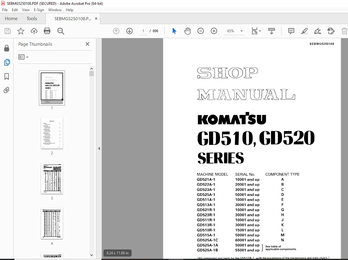
- MACHINE MODEL SERIAL No. COMPONENT TYPE
- GD521A-1 10001 and up А
- GD522A-1 20001 and up B
- GD523A-1 30001 and up C
- GD525A-1 50001 and up D
- GD511A-1 10001 and up E
- GD513A-1 30001 and up F
- GD521R-1 10001 and up G
- GD523R-1 30001 and up H
- GD511R-1 10001 and up J
- GD513R-1 30001 and up K
- GD510R-1 15001 and up L
- GD515A-1 50001 and up M
- GD525A-1C 60001 and up N
- GD525A-1A 50001 and up
- See table of
- GD525A-1B 55001 and up applicable components.
Description
Komatsu GD510,GD520 Series Motor Grader Shop Manual SEBMG5250108 – PDF DOWNLOAD
FILE DETAILS:
Komatsu GD510,GD520 Series Motor Grader Shop Manual SEBMG5250108 – PDF DOWNLOAD
Language : English
Pages : 696
Downloadable : Yes
File Type : PDF
IMAGES PREVIEW OF THE MANUAL:
TABLE OF CONTENTS:
Komatsu GD510,GD520 Series Motor Grader Shop Manual SEBMG5250108 – PDF DOWNLOAD
COVER . 1
CONTENTS 15
1. GENERAL 16
1.1 SPECIFICATIONS 17
1.2 ENGINE EXTERNAL VIEWS . 19
1.3 STRUCTURAL DESCRIPTION 20
2. INSPECTION AND ADJUSTMENT 21
2.1 PERIODIC MAINTENANCE SCHEDULE . 22
2.2 PERIODIC INSPECTION AND MAINTENANCE PROCEDURE . 23
2.2.1 CHECK BEFORE DAILY OPERATION . 23
2.2.2 INSPECTION AFTER INITIAL 50 HOURS OPERATION 25
2.2.3 INSPECTION EVERY 50 HOURS . 28
2.2.4 INSPECTION EVERY 250 HOURS OR 3 MONTHS 32
2.2.5 INSPECTION EVERY 500 HOURS OR 6 MONTHS 35
2.2.6 INSPECTION EVERY 1,000 HOURS OR ONE YEAR 37
2.2.7 INSPECTION EVERY 2000 HOURS OR 2 YEARS 43
2.3 ADJUSTING THE NO-LOAD MAXIMUM OR MINIMUM SPEED 45
2.4 SENSOR INSPECTION . 46
2.4.1 OIL PRESSURE SWITCH . 46
2.4.2 THERMO SWITCH . 46
2.5 WATER LEAK CHECK IN COOLING WATER SYSTEM 46
2.6 RADIATOR CAP INSPECTION . 47
2.7 THERMOSTAT INSPECTION 47
2.8 ADJUSTING OPERATION 48
2.9 LONG STORAGE 48
3. TROUBLESHOOTING 49
3.1 PREPARATION BEFORE TROUBLESHOOTING 50
3.2 QUICK REFERENCE TABLE FOR TROUBLESHOOTING . 51
3.3 TROUBLESHOOTING BY MEASURING COMPRESSION PRESSURE . 54
4. DISASSEMBLY, INSPECTION AND REASSEMBLY OF ENGINES 56
4.1 COMPLETE DISASSEMBLY AND REASSEMBLY . 57
4.1.1 INTRODUCTION 57
4.1.2 SPECIAL SERVICE TOOLS . 58
4.1.3 COMPLETE DISASSEMBLY 63
4.1.4 PRECAUTIONS BEFORE AND DURING REASSEMBLY 67
4.1.5 ADJUSTING OPERATION 67
4.2 CYLINDER HEAD: DISASSEMBLY, INSPECTION AND REASSEMBLY . 68
4.2.1 COMPONENTS (2-VALVE CYLINDER HEAD) 68
4.2.2 DISASSEMBLY PROCEDURE . 69
4.2.3 REASSEMBLY PROCEDURE 69
4.2.4 SERVICING POINTS 70
4.2.5 PARTS INSPECTION AND MEASUREMENT 74
4.2.6 VALVE SEAT CORRECTION 78
4.2.7 VALVE GUIDE REPLACEMENT 79
4.2.8 VALVE STEM SEAL REPLACEMENT . 80
4.3 GEAR TRAIN AND CAMSHAFT . 81
4.3.1 COMPONENTS 81
4.3.2 DISASSEMBLY PROCEDURE . 81
4.3.3 REASSEMBLY PROCEDURE 82
4.3.4 SERVICING POINTS 82
4.3.5 PARTS INSPECTION AND MEASUREMENT . 85
4.3.6 OIL SEAL REPLACEMENT (GEAR CASE SIDE) . 86
4.3.7 CAMSHAFT BUSHING REPLACEMENT . 86
4.4 CYLINDER BLOCK 87
4.4.1 COMPONENTS 87
4.4.2 DISASSEMBLY PROCEDURE . 88
4.4.3 REASSEMBLY PROCEDURE 88
4.4.4 SERVICING POINTS 88
4.4.5 PARTS INSPECTION AND MEASUREMENT 92
4.4.6 CYLINDER BORE CORRECTION 101
4.4.7 PISTON PIN METAL REPLACEMENT .102
4.4.8 OIL SEAL REPLACEMENT (FLYWHEEL HOUSING SIDE) 102
5. LUBRICATION SYSTEM 103
5.1 LUBRICATION SYSTEM DIAGRAM 104
5.2 TROCHOID PUMP COMPONENTS 105
5.3 DISASSEMBLY (REVERSE THE PROCEDURE BELOW FOR ASSEMBLY) 105
5.4 SERVICING POINTS 105
5.5 PARTS INSPECTION AND MEASUREMENT .106
6. COOLING SYSTEM 107
6.1 COOLING WATER SYSTEM .108
6.2 COOLING WATER PUMP COMPONENTS .108
6.3 DISASSEMBLY (REVERSE THE PROCEDURE BELOW FOR ASSEMBLY) 109
6.4 SERVICING POINTS 109
7. FUEL INJECTION PUMP/GOVERNOR .110
7.1 INTRODUCTION .111
7.2 FUEL INJECTION PUMP .111
7.2.1 FUEL SYSTEM DIAGRAM .111
7.2.2 EXTERNAL VIEW AND COMPONENTS 112
7.2.3 DISASSEMBLY PROCEDURE .113
7.2.4 ASSEMBLY PROCEDURE 113
7.2.5 CONFIRMATION AND ADJUSTMENT OF FUEL INJECTION TIMING 113
7.2.6 CONFIRMATION AND ADJUSTMENT OF NO-LOAD MAXIMUM AND MINIMUM SPEED 113
8. THE SPECIFICATIONS OF A STARTING MOTOR AND THE CHARACTERISTICS .114
8.1 THE SPECIFICATIONS AND THE CHARACTERISTICS 115
8.1.1 SPECIFICATIONS 115
8.1.2 CHARACTERISTICS .115
8.2 THE STRUCTURE OF A STARTING MOTOR AND THE WIRING DIAGRAM 116
8.2.1 STRUCTURE .116
8.2.2 WIRING DIAGRAM OF A STARTING MOTOR 117
8.3 PERFORMANCE .117
9. ALTERNATOR .118
9.1 20A ALTERNATOR 119
9.1.1 SPECIFICATIONS 119
9.1.2 STRUCTURE .120
9.1.3 WIRING DIAGRAM 121
9.1.4 STANDARD OUTPUT CHARACTERISTICS .121
9.1.5 INSPECTION 122
9.2 40A ALTERNATOR .123
9.2.1 COMPONENTS 123
9.2.2 SPECIFICATIONS 124
9.2.3 WIRING DIAGRAM 124
9.2.4 STANDARD OUTPUT CHARACTERISTICS 125
9.2.5 INSPECTION 125
9.2.6 TROUBLESHOOTING 126
10.ELECTRIC WIRING .127
10.1 ELECTRIC WIRING DIAGRAM 128
10.2 PRECAUTION ON ELECTRIC WIRING 130
10.2.1 ALTERNATOR .130
10.2.2 STARTING MOTOR .131
10.2.3 CURRENT LIMITER 132
10.2.4 SECTION AREA AND RESISTANCE OF ELECTRIC WIRE .133
11.SERVICE STANDARDS 134
11.1 ENGINE TUNING 135
11.2 ENGINE BODY 136
11.2.1 CYLINDER HEAD 136
11.2.2 GEAR TRAIN AND CAMSHAFT 137
11.2.3 CYLINDER BLOCK 138
11.3 LUBRICATING OIL SYSTEM (TROCHOID PUMP) .141
12.TIGHTENING TORQUE FOR BOLTS AND NUTS .142
12.1 TIGHTENING TORQUES FOR MAIN BOLTS AND NUTS .143
12.2 TIGHTENING TORQUES FOR STANDARD BOLTS AND NUTS .144
DESCRIPTION:
Komatsu GD510,GD520 Series Motor Grader Shop Manual SEBMG5250108 – PDF DOWNLOAD
- MACHINE MODEL SERIAL No. COMPONENT TYPE
- GD521A-1 10001 and up А
- GD522A-1 20001 and up B
- GD523A-1 30001 and up C
- GD525A-1 50001 and up D
- GD511A-1 10001 and up E
- GD513A-1 30001 and up F
- GD521R-1 10001 and up G
- GD523R-1 30001 and up H
- GD511R-1 10001 and up J
- GD513R-1 30001 and up K
- GD510R-1 15001 and up L
- GD515A-1 50001 and up M
- GD525A-1C 60001 and up N
- GD525A-1A 50001 and up
- See table of
- GD525A-1B 55001 and up applicable components.GENERAL PRECAUTIONS:
1. Before carrying out any greasing or repairs, read all the precautions given on the decals which are fixed to the machine.
2. When carrying out any operation, always wear safety shoes and helmet. Do not wear loose work clothes, or clothes with buttons missing.
• Always wear safety glasses when hitting parts with a hammer.
• Always wear safety glasses when grinding parts with a grinder, etc.
3. If welding repairs are needed, always have a trained, experienced welder carry out the work. When carrying out welding work, always wear welding gloves, apron, hand shield, cap and other clothes suited for welding work.
4. When carrying out any operation with two or more workers, always agree on the operating procedure before starting. Always inform your fellow workers before starting any step of the operation. Before starting work, hang UNDER REPAIR signs on the controls in the operator’s compartment.
5. Keep all tools in good condition and learn the correct way to use them.
PREPARATIONS FOR WORK:
7. Before adding oil or making any repairs, park the
machine on hard, level ground, and block the wheels or tracks to prevent the machine from moving.
8. Before starting work, lower blade, ripper, bucket
or any other work equipment to the ground. If this is not possible, insert the safety pin or use blocks to prevent the work equipment from fall- ing. In addition, be sure to lock all the control levers and hang warning signs on them. 9. When disassembling or assembling, support the machine with blocks, jacks or stands before starting work.
10. Remove all mud and oil from the steps or other places used to get on and off the machine. Always use the handrails, ladders or steps when getting on or off the machine. Never jump on or off the machine. If it is impossible to use the handrails, ladders or steps, use a stand to pro- vide safe footing.
11. When removing the oil filler cap, drain plug or hydraulic pressure measuring plugs, loosen them slowly to prevent the oil from spurting out. Before disconnecting or removing components of the oil, water or air circuits, first remove the pressure completely from the circuit.
12.The water and oil in the circuits are hot when the engine is stopped, so be careful not to get burned.
Wait for the oil and water to cool before carry- ing out any work on the oil or water circuits.
13. Before starting work, remove the leads from the battery. Always remove the lead from the nega- tive (-) terminal first.
14. When raising heavy components, use a hoist or crane.
Check that the wire rope, chains and hooks are free from damage.
Always use lifting equipment which has ample capacity.
Install the lifting equipment at the correct places. Use a hoist or crane and operate slowly to pre- vent the component from hitting any other part. Do not work with any part still raised by the hoist or crane.
15. When removing covers which are under internal
pressure or under pressure from a spring, always leave two bolts in position on opposite sides. Slowly release the pressure, then slowly loosen the bolts to remove.
16. When removing components, be careful not to break or damage the wiring. Damaged wiring may cause electrical fires.
17. When removing piping, stop the fuel or oil from spilling out. If any fuel or oil drips onto the floor, wipe it up immediately. Fuel or oil on the floor can cause you to slip, or can even start fires.
18.As a general rule, do not use gasoline to wash parts. In particular, use only the minimum of gasoline when washing electrical parts.
G.B 25/12/24



