KOMATSU GD535-5 MOTOR GRADER SHOP MANUAL SEN06650-07 – PDF DOWNLOAD
$38.95
KOMATSU GD535-5 MOTOR GRADER SHOP MANUAL SEN06650-07 – PDF DOWNLOAD
Description
KOMATSU GD535-5 MOTOR GRADER SHOP MANUAL SEN06650-07 – PDF DOWNLOAD
FILE DETAILS:
KOMATSU GD535-5 MOTOR GRADER SHOP MANUAL SEN06650-07 – PDF DOWNLOAD
Language : English
Pages : 1578
Downloadable : Yes
File Type : PDF
IMAGES PREVIEW OF THE MANUAL:
TABLE OF CONTENTS:
KOMATSU GD535-5 MOTOR GRADER SHOP MANUAL SEN06650-07 – PDF DOWNLOAD
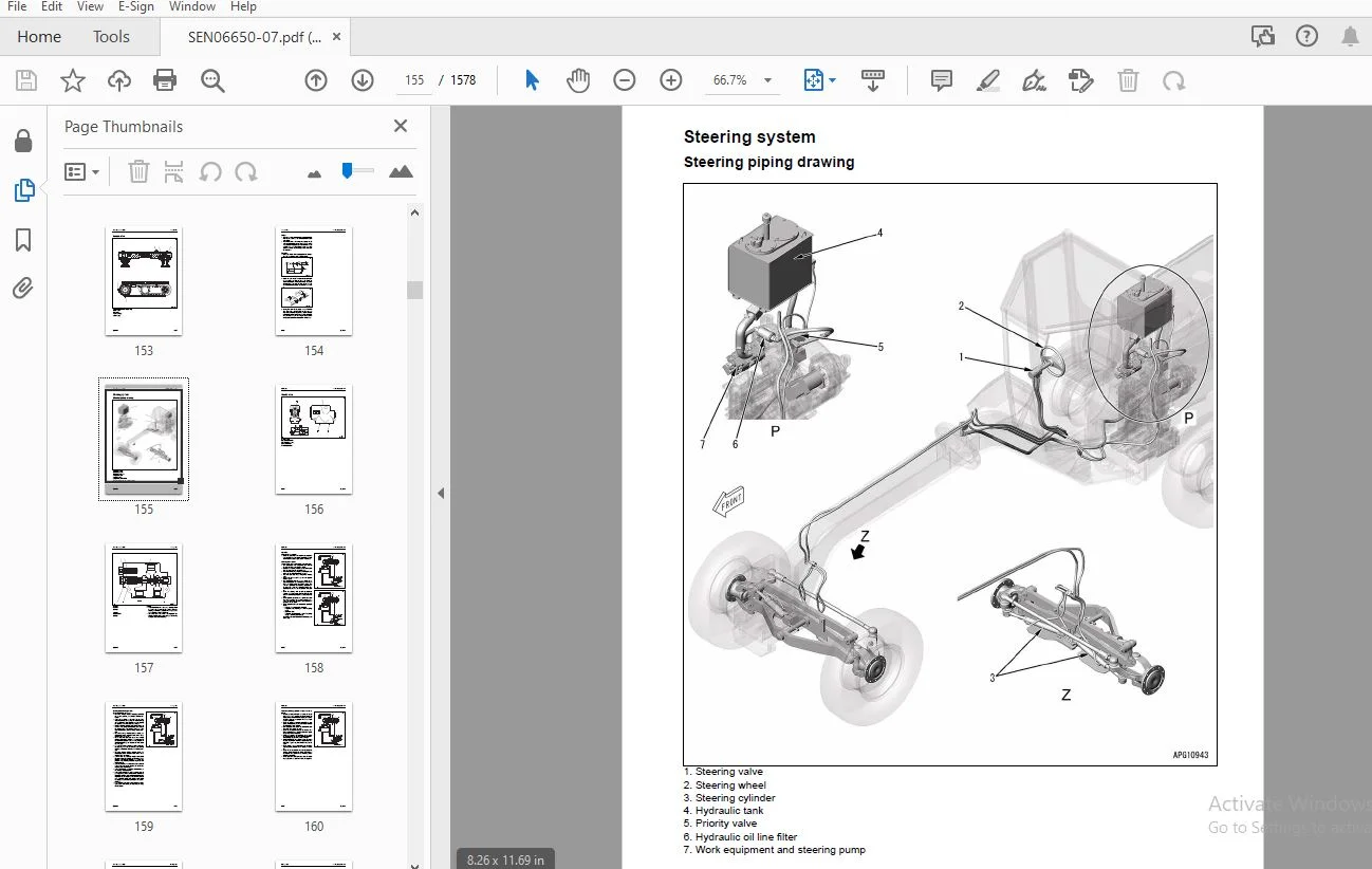
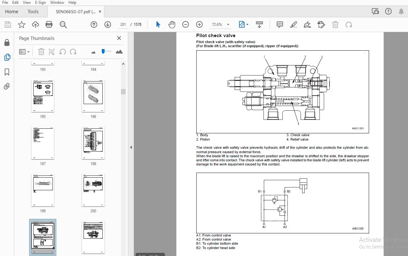
Cover...................................................................................................................   1
Notice of revision......................................................................................................   3
00 Index and foreword...................................................................................................  11
	Table of contents...................................................................................................  12
	Acronyms............................................................................................................  24
	Foreword and general information....................................................................................  29
		Safety notice...................................................................................................  29
		How to read the shop manual.....................................................................................  34
		Explanation of terms for maintenance standard...................................................................  36
		Handling of electric equipment and hydraulic components.........................................................  38
		Handling of connectors newly used for engines...................................................................  47
		How to read electric wire code..................................................................................  50
		Precautions when carrying out work..............................................................................  53
		Method of disassembling and connecting push-pull type coupler...................................................  56
		Standard tightening torque table................................................................................  59
		Conversion table................................................................................................  63
01 Specification........................................................................................................  69
	Contents............................................................................................................  70
	Acronyms............................................................................................................  71
	Specifications......................................................................................................  76
		Specification drawing...........................................................................................  76
		Specifications..................................................................................................  78
		Weight table....................................................................................................  84
		Table of fuel, coolant, and lubricants..........................................................................  85
10 Structure and function...............................................................................................  87
	Contents............................................................................................................  88
	Acronyms............................................................................................................  90
	Engine and cooling system...........................................................................................  95
		Cooling system..................................................................................................  95
		Cooling fan motor...............................................................................................  97
	Power train system.................................................................................................. 105
		Power train system drawing...................................................................................... 105
		Power train piping drawing...................................................................................... 106
		Transmission control............................................................................................ 107
		Torque converter................................................................................................ 108
		Transmission.................................................................................................... 111
		Transmission control valve...................................................................................... 130
		ECMV............................................................................................................ 132
		Main relief valve and torque converter relief valve............................................................. 139
		Front axle...................................................................................................... 141
		Rear axle....................................................................................................... 144
		Differential (Non-differential specification)................................................................... 145
		Differential (Differential lock specification).................................................................. 147
		Differential lock solenoid valve................................................................................ 150
		Final drive..................................................................................................... 151
		Tandem drive.................................................................................................... 153
	Steering system..................................................................................................... 155
		Steering piping drawing......................................................................................... 155
		Priority valve.................................................................................................. 156
		Steering valve.................................................................................................. 161
	Brake system........................................................................................................ 168
		Hydraulic piping drawing of brake system........................................................................ 168
		Brake valve..................................................................................................... 169
		Brake circuit accumulator....................................................................................... 174
		Brake circuit accumulator charge valve.......................................................................... 175
		Wheel brake..................................................................................................... 181
		Parking brake solenoid valve and lifter lock pin solenoid valve................................................. 182
		Parking brake................................................................................................... 183
	Undercarriage and frame............................................................................................. 184
		Frame........................................................................................................... 184
		Tire............................................................................................................ 185
	Hydraulic system.................................................................................................... 186
		Hydraulic system................................................................................................ 186
		Hydraulic piping drawing of work equipment...................................................................... 188
		Work equipment control.......................................................................................... 190
		Hydraulic tank.................................................................................................. 191
		Work equipment pump and steering pump........................................................................... 192
		Power train pump................................................................................................ 193
		Power train pump and differential lock pump..................................................................... 194
		Brake and cooling fan pump...................................................................................... 195
		Control valve................................................................................................... 196
		Functions and valve operations.................................................................................. 198
		Hydraulic cylinder.............................................................................................. 199
		Swivel joint.................................................................................................... 200
		Pilot check valve............................................................................................... 201
	Work equipment system............................................................................................... 210
		Circle and drawbar.............................................................................................. 210
		Blade........................................................................................................... 212
		Lifter.......................................................................................................... 214
		Circle rotation motor........................................................................................... 216
		Circle rotation gear............................................................................................ 218
		Ripper.......................................................................................................... 220
	Cab and its attachments............................................................................................. 221
		ROPS cab........................................................................................................ 221
	Electrical system................................................................................................... 222
		Layout drawing of electrical system............................................................................. 222
		System operating lamp system.................................................................................... 224
		Battery disconnect switch....................................................................................... 225
		Machine monitor................................................................................................. 226
		Automatic gear shift control system............................................................................. 237
		Transmission controller......................................................................................... 242
		Engine controller............................................................................................... 245
		KOMTRAX system.................................................................................................. 248
		KOMTRAX terminal................................................................................................ 249
		Rearview monitor system......................................................................................... 251
		Rearview monitor................................................................................................ 252
		Rearview camera................................................................................................. 253
		Engine starting circuit......................................................................................... 254
		Engine stop circuit............................................................................................. 256
		Preheating circuit.............................................................................................. 257
		Sensors......................................................................................................... 258
		Engine power mode selector circuit.............................................................................. 267
		Cooling fan control system...................................................................................... 268
20 Standard value table................................................................................................. 271
	Contents............................................................................................................ 272
	Acronyms............................................................................................................ 273
	Standard value table................................................................................................ 278
		Standard value table for engine................................................................................. 278
		Standard value table for machine................................................................................ 280
30 Testing and adjusting................................................................................................ 291
	Contents............................................................................................................ 292
	Acronyms............................................................................................................ 294
	Tools for testing, adjusting, and troubleshooting................................................................... 299
		Tools for testing, adjusting, and troubleshooting............................................................... 299
	Engine and cooling system........................................................................................... 306
		Testing engine speed............................................................................................ 306
		Testing boost pressure.......................................................................................... 308
		Testing exhaust gas temperature................................................................................. 310
		Testing exhaust gas color....................................................................................... 312
		Adjusting valve clearance....................................................................................... 314
		Testing compression pressure.................................................................................... 316
		Testing blowby pressure......................................................................................... 319
		Testing engine oil pressure..................................................................................... 320
		Handling fuel system devices.................................................................................... 321
		Releasing remaining pressure from fuel system................................................................... 322
		Testing fuel pressure........................................................................................... 323
		Bleeding air from fuel circuit.................................................................................. 324
		Testing fuel circuit for leakage................................................................................ 325
		Handling cylinder cutout mode operation......................................................................... 326
		Handling no-injection cranking operation........................................................................ 327
		Handling voltage circuit of engine controller................................................................... 328
		Testing muffler (main body) and stacked muffler for looseness and damage........................................ 329
		Testing muffler function........................................................................................ 330
		Testing installed condition of cylinder heads and manifolds..................................................... 331
		Testing of engine piping for damage and looseness............................................................... 332
		Testing fuel discharge, return rate, and leakage................................................................ 333
		Testing and adjusting air conditioner compressor belt tension................................................... 337
		Checking and replacing alternator belt.......................................................................... 339
		Checking and replacing auto-tensioner........................................................................... 341
	Power train......................................................................................................... 344
		Testing power train oil pressure................................................................................ 344
		Adjusting transmission speed sensor............................................................................. 358
		Retrieval of disabled machine due to transmission valve failure................................................. 361
		Flushing procedure for torque converter and transmission circuits............................................... 364
		Testing and adjusting toe-in.................................................................................... 366
		Adjusting bearing preload....................................................................................... 368
		Testing and adjusting differential lock oil pressure (differential lock specification).......................... 370
	Steering system..................................................................................................... 372
		Testing and adjusting steering oil pressure..................................................................... 372
		Testing oil leakage of steering cylinder........................................................................ 373
		Bleeding air from steering circuit.............................................................................. 374
	Brake system........................................................................................................ 375
		Releasing remaining pressure from brake circuit................................................................. 375
		Testing and adjusting brake oil pressure........................................................................ 376
		Bleeding air from brake circuit................................................................................. 379
		Testing wear of wheel brake disc................................................................................ 380
		Testing and adjusting parking brake pad......................................................................... 381
		Releasing parking brake manually................................................................................ 384
		Charging brake accumulator with gas............................................................................. 385
	Hydraulic system.................................................................................................... 387
		Testing work equipment oil pressure............................................................................. 387
		Testing lifter lock pin circuit pressure........................................................................ 389
		Testing cooling fan speed....................................................................................... 391
		Testing cooling fan circuit oil pressure........................................................................ 392
		Testing oil leakage of work equipment cylinder.................................................................. 394
		Bleeding air from work equipment circuit........................................................................ 397
	Work equipment...................................................................................................... 398
		Adjusting drawbar ball joint clearance.......................................................................... 398
		Testing and adjusting circle guide clearance.................................................................... 399
		Testing and adjusting slip clutch type circle drive............................................................. 401
	Electrical system................................................................................................... 403
		Procedure for testing diodes.................................................................................... 403
		Special functions of machine monitor............................................................................ 405
		Handling high-voltage circuit of engine controller.............................................................. 454
		KOMTRAX terminal start-up procedure............................................................................. 455
		Adjusting rearview camera angle................................................................................. 459
		Handle battery disconnect switch................................................................................ 461
		Preparatory work for troubleshooting of electrical system failure............................................... 462
	Pm Clinic........................................................................................................... 464
		Pm Clinic....................................................................................................... 464
40 Troubleshooting...................................................................................................... 475
	Contents............................................................................................................ 476
	Acronyms............................................................................................................ 482
	Information related to troubleshooting.............................................................................. 487
		Points to remember when troubleshooting......................................................................... 487
		How to proceed in troubleshooting............................................................................... 488
		Checks before troubleshooting................................................................................... 489
		Inspection procedure before troubleshooting..................................................................... 491
		Troubleshooting procedure....................................................................................... 506
		Failure code list............................................................................................... 508
		Symptoms and troubleshooting numbers............................................................................ 516
		Information described in troubleshooting table.................................................................. 519
		Diagnosis of open harness in pressure sensor system............................................................. 521
		Connector list and layout....................................................................................... 523
		Connector pin layout............................................................................................ 537
		T-box and T-adapter list........................................................................................ 573
		Locations of fuses.............................................................................................. 578
	Troubleshooting by failure code (display of code)................................................................... 581
		Failure code [1500L0] Double Engagement of T/M Clutches......................................................... 581
		Failure code [15G0MW] Failure of R-Clutch System................................................................ 582
		Failure code [15H0MW] Failure of Clutch System (FH)............................................................. 583
		Failure code [15J0MW] Failure of Clutch System (FL)............................................................. 584
		Failure code [15K0MW] Failure of Clutch System (1st)............................................................ 585
		Failure code [15L0MW] Failure of Clutch System (2nd)............................................................ 586
		Failure code [15M0MW] Failure of Clutch System (3rd)............................................................ 587
		Failure code [15N0MW] Failure of Clutch System (4th)............................................................ 588
		Failure code [15SBL1] Release Trouble of ECMV (R)............................................................... 589
		Failure code [15SBMA] Malfunction of ECMV (R)................................................................... 591
		Failure code [15SCL1] Release Trouble of ECMV (FH).............................................................. 593
		Failure code [15SCMA] Malfunction of ECMV (FH).................................................................. 595
		Failure code [15SDL1] Release Trouble of ECMV (FL).............................................................. 597
		Failure code [15SDMA] Malfunction of ECMV (FL).................................................................. 599
		Failure code [15SEL1] Release Trouble of ECMV (1st)............................................................. 601
		Failure code [15SEMA] Malfunction of ECMV (1st)................................................................. 603
		Failure code [15SFL1] Release Trouble of ECMV (2nd)............................................................. 605
		Failure code [15SFMA] Malfunction of ECMV (2nd)................................................................. 607
		Failure code [15SGL1] Release Trouble of ECMV (3rd)............................................................. 609
		Failure code [15SGMA] Malfunction of ECMV (3rd)................................................................. 611
		Failure code [15SHL1] Release Trouble of ECMV (4th)............................................................. 613
		Failure code [15SHMA] Malfunction of ECMV (4th)................................................................. 615
		Failure code [15SJMA] Malfunction of ECMV (L/U)................................................................. 617
		Failure code [15U0NT] Overload of Inching Clutch................................................................ 618
		Failure code [2G42ZG] Accumulator Oil Pressure Low (Front)...................................................... 619
		Failure code [2G43ZG] Accumulator Oil Pressure Low (Rear)....................................................... 621
		Failure code [989L00] Engine Controller Lock Caution 1.......................................................... 623
		Failure code [989M00] Engine Controller Lock Caution 2.......................................................... 624
		Failure code [989N00] Engine Controller Lock Caution 3.......................................................... 625
		Failure code [AB00KE] Charge Voltage Low........................................................................ 626
		Failure code [AB00KY] Hot Short of Alternator R Terminal........................................................ 627
		Failure code [B@BAZG] Derating in speed due to engine oil pressure drop......................................... 628
		Failure code [B@BCNS] Engine Overheat........................................................................... 629
		Failure code [B@CENS] T/C Oil Temp. Overheat.................................................................... 630
		Failure code [B@CKNS] DIFF Oil Temp. Overheat................................................................... 631
		Failure code [B@HANS] HYD Oil Temp. Overheat.................................................................... 633
		Failure code [CA111] Engine NE, controller internal error....................................................... 635
		Failure code [CA115] Engine NE, Bkup speed sensor error......................................................... 636
		Failure code [CA122] Charge pressure sensor high error.......................................................... 637
		Failure code [CA123] Charge pressure sensor low error........................................................... 639
		Failure code [CA131] Throttle sensor high error................................................................. 641
		Failure code [CA132] Throttle sensor low error.................................................................. 643
		Failure code [CA144] Coolant sensor high error.................................................................. 646
		Failure code [CA145] Coolant sensor low error................................................................... 648
		Failure code [CA153] Charge temperature sensor high error....................................................... 650
		Failure code [CA154] Charge temperature sensor low error........................................................ 652
		Failure code [CA155] Speed derating error by high charge temperature............................................ 654
		Failure code [CA187] Sensor power supply 2 low error............................................................ 655
		Failure code [CA221] Atmospheric pressure sensor high error..................................................... 657
		Failure code [CA222] Atmospheric pressure sensor low error...................................................... 659
		Failure code [CA227] Sensor power supply 2 high error........................................................... 661
		Failure code [CA234] Engine overspeed........................................................................... 662
		Failure code [CA238] Ne speed sensor power supply error......................................................... 663
		Failure code [CA271] IMV short-circuit error.................................................................... 664
		Failure code [CA272] IMV open circuit........................................................................... 666
		Failure code [CA322] Injector #1 (L/B #1) open/short............................................................ 668
		Failure code [CA323] Injector #5 (L/B #5) open/short............................................................ 670
		Failure code [CA324] Injector #3 (L/B #3) open/short............................................................ 672
		Failure code [CA325] Injector #6 (L/B #6) open/short............................................................ 674
		Failure code [CA331] Injector #2 (L/B #2) open/short............................................................ 676
		Failure code [CA332] Injector #4 (L/B #4) open/short............................................................ 678
		Failure code [CA342] Data compatibility error in engine controller.............................................. 680
		Failure code [CA351] Injector drive circuit error............................................................... 681
		Failure code [CA352] Sensor power supply 1 low error............................................................ 682
		Failure code [CA386] Sensor power supply 1 high error........................................................... 684
		Failure code [CA428] Water-in-fuel sensor high error............................................................ 685
		Failure code [CA429] Water-in-fuel sensor low error............................................................. 687
		Failure code [CA431] Idle validation switch error............................................................... 689
		Failure code [CA432] Idle validation action error............................................................... 693
		Failure code [CA435] Engine oil pressure switch error........................................................... 696
		Failure code [CA441] Power supply voltage low error............................................................. 697
		Failure code [CA442] Power supply voltage high error............................................................ 699
		Failure code [CA449] Common rail pressure high error 2.......................................................... 700
		Failure code [CA451] Common rail pressure sensor high error..................................................... 701
		Failure code [CA452] Common rail pressure sensor low error...................................................... 703
		Failure code [CA488] Torque derating error by high charge temperature........................................... 705
		Failure code [CA553] Common rail pressure high error 1.......................................................... 706
		Failure code [CA559] Supply pump pressure low error 1........................................................... 707
		Failure code [CA689] Engine Ne speed sensor error............................................................... 709
		Failure code [CA731] Engine Bkup speed sensor phase error....................................................... 711
		Failure code [CA757] All continuous data lost error............................................................. 713
		Failure code [CA778] Engine Bkup speed sensor error............................................................. 714
		Failure code [CA1633] KOMNET (CAN communication) error.......................................................... 718
		Failure code [CA2185] Throttle sensor power supply high error................................................... 722
		Failure code [CA2186] Throttle sensor power supply low error.................................................... 724
		Failure code [CA2249] Supply pump pressure low error 2.......................................................... 726
		Failure code [CA2311] Abnormality in IMV (IMA) solenoid......................................................... 727
		Failure code [CA2555] Intake heater relay open circuit.......................................................... 728
		Failure code [CA2556] Intake heater relay short circuit......................................................... 730
		Failure code [D160KA] Disconnection of Backup Light Relay....................................................... 732
		Failure code [D160KB] Ground Fault of Backup Light Relay........................................................ 734
		Failure code [D160KY] Hot Short of Back Lamp Relay Output....................................................... 736
		Failure code [D19JKZ] Personal Code Relay Abnormality........................................................... 738
		Failure code [D19KKZ] Failure of Diff Control Relay............................................................. 740
		Failure code [D1EHKA] Disconnection of Engine Start Relay....................................................... 742
		Failure code [D1EHKB] Ground Fault of Engine Start Relay........................................................ 743
		Failure code [D1EHKY] Hot Short of Engine Start Relay........................................................... 744
		Failure code [D1FBKB] Ground Fault of Sol. Self-Holding Relay................................................... 745
		Failure code [D8AQK4] CAN2 Discon (KOMTRAX) 2................................................................... 747
		Failure code [D8AQKR] CAN2 Discon (KOMTRAX)..................................................................... 748
		Failure code [DAF0KT] Abnormality of Non-volatile Memory (MON).................................................. 750
		Failure code [DAF0MB] Monitor ROM Abnormality................................................................... 751
		Failure code [DAF0MC] Monitor Error............................................................................. 752
		Failure code [DAF3KK] Controller Power Source Low (MON)......................................................... 753
		Failure code [DAFLKA] Op Lamp Open Cir (Mon).................................................................... 755
		Failure code [DAFLKB] Op Lamp Shrt Cir (Mon).................................................................... 757
		Failure code [DAQ0KK] Controller Power Source Low (T/M)......................................................... 759
		Failure code [DAQ0KT] Abnormality of Non-volatile Memory (T/M).................................................. 761
		Failure code [DAQ0MC] T/M Con Error............................................................................. 762
		Failure code [DAQ1KA] Disconnection of Key SW ACC............................................................... 763
		Failure code [DAQ2KK] Solenoid Power Source Low (T/M)........................................................... 765
		Failure code [DAQ9KQ] Inconsistency of Model Selection (T/M).................................................... 767
		Failure code [DAQLKA] Op Lamp Open Cir (T/M Cont)............................................................... 768
		Failure code [DAQLKB] Op Lamp Shrt Cir (T/M Cont)............................................................... 770
		Failure code [DAQQKR] CAN2 Discon (Transmission Con)............................................................ 772
		Failure code [DAQRMA] Inconsistency of Option Selection (T/M)................................................... 773
		Failure code [DB2QKR] CAN2 Discon (Engine Con).................................................................. 774
		Failure code [DD1PKB] Abnormality of RPM Switch................................................................. 778
		Failure code [DD1QKB] Abnormality of RPM Set Mode Switch........................................................ 780
		Failure code [DDB6L4] Parking brake signal error................................................................ 782
		Failure code [DDTHKA] Disconnection of Fill Switch (FH)......................................................... 784
		Failure code [DDTJKA] Disconnection of Fill Switch (FL)......................................................... 785
		Failure code [DDTKKA] Disconnection of Fill Switch (1st)........................................................ 786
		Failure code [DDTLKA] Disconnection of Fill Switch (2nd)........................................................ 787
		Failure code [DDTMKA] Disconnection of Fill Switch (3rd)........................................................ 788
		Failure code [DDTNKA] Disconnection of Fill Switch (R).......................................................... 789
		Failure code [DDTPKA] Disconnection of Fill Switch (4th)........................................................ 790
		Failure code [DF10KA] Disconnection of Shift Lever Input........................................................ 791
		Failure code [DF10L4] Gear Speed/Travel Direction Signal Error.................................................. 795
		Failure code [DGF1KX] Out of Range of T/M Oil Temp. Sensor...................................................... 798
		Failure code [DGH2KB] Ground Fault of Hydraulic Oil Temp. S..................................................... 800
		Failure code [DGT1KX] Out of Range of T/C Oil Temp. Sensor...................................................... 802
		Failure code [DGT7KB] Ground Fault of Diff Oil Temp. S.(C)...................................................... 804
		Failure code [DHT5KX] Out of Range of T/C Input Pressure Sensor................................................. 805
		Failure code [DHT5L6] Failure of T/C Oil Press Sensor........................................................... 807
		Failure code [DJF1KA] Disconnection of Fuel Level Sensor........................................................ 809
		Failure code [DK70KX] Out of Range of Inching Potentio.......................................................... 811
		Failure code [DKD0KX] Out of Range of Articulated Angle Sensor.................................................. 813
		Failure code [DLF1KA] Disconnection of T/M Input Speed Sensor................................................... 815
		Failure code [DLF1LC] Failure of T/M Input Speed Sensor......................................................... 817
		Failure code [DLF2KA] Disconnection of T/M Inter. Speed Sensor.................................................. 819
		Failure code [DLF2LC] Failure of T/M Intermediate Speed Sensor.................................................. 821
		Failure code [DLM3KA] Rad Fan Spd Sen Opn/Shrt Cir.............................................................. 823
		Failure code [DLM3LC] Rad Fan Spd Sen Sig Error................................................................. 825
		Failure code [DLM3MB] Rad Fan Spd Sen Error..................................................................... 826
		Failure code [DLT3KA] Disconnection of T/M output Speed Sensor.................................................. 827
		Failure code [DW4BKA] Disconnection of Parking Brake Valve...................................................... 829
		Failure code [DW4BKB] Ground Fault of Parking Brake Valve....................................................... 831
		Failure code [DW4BKY] Hot Short of Parking Brake Solenoid....................................................... 833
		Failure code [DW7BKA] Rad Fan R Sol Opn Cir..................................................................... 835
		Failure code [DW7BKB] Rad Fan R Sol Gnd Flt..................................................................... 837
		Failure code [DW7BKY] Rad Fan R Sol Shrt Cir.................................................................... 839
		Failure code [DX16KA] Rad Fan Pump EPC Sol Opn Cir.............................................................. 841
		Failure code [DX16KB] Rad Fan Pump EPC Sol Gnd Flt.............................................................. 843
		Failure code [DX16KY] Rad Fan Pmp EPC Sol Shrt Cir.............................................................. 845
		Failure code [DXH1KA] Disconnection of ECMV Solenoid (Lockup)................................................... 847
		Failure code [DXH1KB] Ground Fault of ECMV Solenoid (Lockup).................................................... 849
		Failure code [DXH1KY] Hot Short of ECMV Solenoid (Lockup)....................................................... 851
		Failure code [DXH2KA] Disconnection of ECMV Solenoid (High)..................................................... 853
		Failure code [DXH2KB] Ground Fault of ECMV Solenoid (High)...................................................... 855
		Failure code [DXH2KY] Hot Short of ECMV Solenoid (High)......................................................... 857
		Failure code [DXH3KA] Disconnection of ECMV Solenoid (Low)...................................................... 859
		Failure code [DXH3KB] Ground Fault of ECMV Solenoid (Low)....................................................... 861
		Failure code [DXH3KY] Hot Short of ECMV Solenoid (Low).......................................................... 863
		Failure code [DXH4KA] Disconnection of ECMV Solenoid (1st)...................................................... 865
		Failure code [DXH4KB] Ground Fault of ECMV Solenoid (1st)....................................................... 867
		Failure code [DXH4KY] Hot Short of ECMV Solenoid (1st).......................................................... 869
		Failure code [DXH5KA] Disconnection of ECMV Solenoid (2nd)...................................................... 871
		Failure code [DXH5KB] Ground Fault of ECMV Solenoid (2nd)....................................................... 873
		Failure code [DXH5KY] Hot Short of ECMV Solenoid (2nd).......................................................... 875
		Failure code [DXH6KA] Disconnection of ECMV Solenoid (3rd)...................................................... 877
		Failure code [DXH6KB] Ground Fault of ECMV Solenoid (3rd)....................................................... 879
		Failure code [DXH6KY] Hot Short of ECMV Solenoid (3rd).......................................................... 881
		Failure code [DXH7KA] Disconnection of ECMV Solenoid (Reverse).................................................. 883
		Failure code [DXH7KB] Ground Fault of ECMV Solenoid (Reverse)................................................... 885
		Failure code [DXH7KY] Hot Short of ECMV Solenoid (Reverse)...................................................... 887
		Failure code [DXHHKA] Disconnection of ECMV Solenoid (4th)...................................................... 889
		Failure code [DXHHKB] Ground Fault of ECMV Solenoid (4th)....................................................... 891
		Failure code [DXHHKY] Hot Short of ECMV Solenoid (4th).......................................................... 893
	Troubleshooting of electrical system (E-mode)....................................................................... 895
		E-1 Engine does not start (Starting motor does not rotate)...................................................... 895
		E-2 Manual preheating system does not work...................................................................... 899
		E-3 When starting switch is turned ON, machine monitor displays nothing......................................... 905
		E-4 LCD panel backlight of machine monitor fails (goes out or flickers)......................................... 908
		E-5 LCD display failure of machine monitor...................................................................... 909
		E-6 The switch of machine monitor switch panel does not work.................................................... 910
		E-7 Two-switch operation of switch panel on machine monitor does not function................................... 911
		E-8 Machine monitor buzzer does not sound....................................................................... 912
		E-9 Some gauges or caution lamps of machine monitor do not work normally........................................ 913
		E-10 Rearview monitor does not light up or backlight flickers................................................... 914
		E-11 Rearview monitor images are not displayed clearly.......................................................... 916
		E-12 Rearview monitor brightness cannot be adjusted............................................................. 918
		E-13 Night lighting lamp of rearview monitor is abnormal........................................................ 921
		E-14 Speedometer or engine speed display is abnormal............................................................ 923
		E-15 Engine coolant temperature is displayed abnormally......................................................... 924
		E-16 Articulated meter display is abnormal...................................................................... 926
		E-17 Torque converter oil temperature is displayed abnormally................................................... 928
		E-18 Fuel gauge is displayed abnormally......................................................................... 930
		E-19 Centralized warning lamps do not light or do not go out.................................................... 932
		E-20 Alarm buzzer does not sound or does not stop sounding...................................................... 933
		E-21 Transmission mode cannot be switched....................................................................... 935
		E-22 Engine mode cannot be switched............................................................................. 937
		E-23 Differential gear lock function does not operate or is not canceled (for differential gear lock model)..... 939
		E-24 Cannot be locked or canceled by the lifter lock pin........................................................ 941
		E-25 Horn does not sound or does not stop sounding.............................................................. 943
		E-26 Backup alarm does not sound or does not stop sounding...................................................... 945
		E-27 Headlamps, clearance lamps, and tail lamps do not light up or go out....................................... 948
		E-28 Working lamps do not light up or go out.................................................................... 956
		E-29 Turn indicator light or emergency flashing light does not flash............................................ 961
		E-30 Stop lamp does not light up or does not go out............................................................. 970
		E-31 Backup lamp does not light up or does not go out........................................................... 972
		E-32 All wipers do not operate.................................................................................. 974
		E-33 Front wiper does not operate............................................................................... 976
		E-34 Rear wiper does not operate................................................................................ 980
		E-35 Left and right door wiper does not operate................................................................. 983
		E-36 Left door wiper does not operate........................................................................... 986
		E-37 Right door wiper does not operate.......................................................................... 988
		E-38 Front or door washer does not operate...................................................................... 990
		E-39 Rear washer does not operate............................................................................... 992
		E-40 KOMTRAX system does not operate normally................................................................... 994
	Troubleshooting of hydraulic and mechanical system (H-mode)......................................................... 996
		How to use troubleshooting table................................................................................ 996
		H-1 Engine speed drops significantly or engine stalls...........................................................1002
		H-2 Machine does not move off...................................................................................1003
		H-3 Gear speed does not shift...................................................................................1004
		H-4 Travel speed or power is low................................................................................1005
		H-5 Torque converter lockup does not operate or is not canceled.................................................1008
		H-6 Machine starts or gear speed shifts with long time lag......................................................1009
		H-7 Torque converter oil temperature is high....................................................................1012
		H-8 Differential gear lock function does not operate or is not canceled.........................................1015
		H-9 Steering speed or power is insufficient.....................................................................1016
		H-10 Steering wheel does not move...............................................................................1017
		H-11 Wheel brakes do not work or are weak.......................................................................1018
		H-12 Wheel brakes are not released or drag......................................................................1019
		H-13 Parking brake does not work or it is weak..................................................................1020
		H-14 Parking brake (including emergency release system) is not released or drags................................1021
		H-15 All work equipment operates slowly or lacks power..........................................................1022
		H-16 Work equipment does not operate............................................................................1023
		H-17 Unusual noise is heard from around hydraulic pump..........................................................1024
		H-18 Blade lift speed or power is low...........................................................................1025
		H-19 Hydraulic drift of lifted blade is large...................................................................1026
		H-20 Drawbar side shift speed or power is low...................................................................1027
		H-21 Blade side shift speed or power is low.....................................................................1028
		H-22 Power tilt speed or power is low...........................................................................1029
		H-23 Articulate speed or power is low...........................................................................1030
		H-24 Leaning speed or power is insufficient.....................................................................1031
		H-25 Hydraulic drift (tilting) of leaning is large..............................................................1032
		H-26 Blade does not rotate......................................................................................1033
		H-27 Lifter lock pin is not locked or is not canceled...........................................................1034
		H-28 Fan revolution is abnormal (Fan sound/vibration is abnormally large or engine overheats)...................1035
	Troubleshooting of engine (S-mode)..................................................................................1037
		How to read matrix..............................................................................................1037
		S-1 Engine startability is poor.................................................................................1040
		S-2 Engine does not start.......................................................................................1041
		S-3 Engine does not pick-up smoothly............................................................................1044
		S-4 Engine stops during operation...............................................................................1045
		S-5 Engine runs rough or is unstable............................................................................1046
		S-6 Engine lacks power..........................................................................................1047
		S-7 Exhaust smoke is black (Incomplete combustion)..............................................................1048
		S-8 Large oil consumption (or blue exhaust gas).................................................................1049
		S-9 Oil becomes contaminated early..............................................................................1050
		S-10 Fuel consumption is excessive..............................................................................1051
		S-11 Oil is in coolant (or coolant spurts back or coolant level goes down)......................................1052
		S-12 Oil pressure drops.........................................................................................1053
		S-13 Oil amount increases (due to water or fuel mixing).........................................................1054
		S-14 Coolant temperature rises too high (overheating)...........................................................1055
		S-15 Unusual noise is heard.....................................................................................1056
		S-16 Vibration is excessive.....................................................................................1057
		Contents........................................................................................................1060
		Acronyms........................................................................................................1062
50 Disassembly and assembly.............................................................................................1059
	Contents............................................................................................................1060
	Acronyms............................................................................................................1062
	Related information on disassembly and assembly.....................................................................1067
		How to read this manual.........................................................................................1067
		Coating materials list..........................................................................................1069
		Special tool list...............................................................................................1073
		Sketches of special tools.......................................................................................1083
	Engine and cooling system...........................................................................................1129
		Removal and installation of supply pump assembly................................................................1129
		Removal and installation of injector assembly...................................................................1133
		Removal and installation of cylinder head assembly..............................................................1142
		Removal and installation of air conditioner compressor belt.....................................................1160
		Removal and installation of alternator belt.....................................................................1161
		Removal and installation of engine front oil seal...............................................................1163
		Removal and installation of engine rear oil seal................................................................1166
		Removal and installation of cooling fan pump assembly...........................................................1169
		Removal and installation of cooling fan and fan motor assembly..................................................1171
		Removal and installation of radiator assembly...................................................................1175
		Removal and installation of aftercooler assembly................................................................1179
		Removal and installation of power train oil cooler assembly.....................................................1183
		Removal and installation of fuel tank assembly..................................................................1186
		Removal and installation of engine hood assembly................................................................1190
		Removal and installation of air conditioner compressor assembly.................................................1192
	Power train.........................................................................................................1194
		Removal and installation of engine, transmission, and torque converter assembly.................................1194
		Disconnection and connection of engine, transmission, and torque converter assembly.............................1202
		Disassembly and assembly of torque converter assembly...........................................................1204
		Disassembly and assembly of transmission assembly...............................................................1217
		Removal and installation of tandem drive and final drive assembly...............................................1256
		Disassembly and assembly of tandem drive assembly...............................................................1259
		Disassembly and assembly of differential assembly...............................................................1267
		Disassembly and assembly of final drive assembly................................................................1282
	Steering system.....................................................................................................1291
		Removal and installation of Orbitrol valve assembly.............................................................1291
	Brake system........................................................................................................1296
		Disassembly and assembly of wheel brake assembly................................................................1296
	Undercarriage and frame.............................................................................................1304
		Removal and installation of center hinge pin....................................................................1304
	Hydraulic system....................................................................................................1315
		Removal and installation of hydraulic tank, battery, and frame assembly.........................................1315
		Removal and installation of hydraulic tank assembly.............................................................1322
		Removal and installation of control valve assembly..............................................................1326
		Disassembly and assembly of hydraulic cylinder assembly.........................................................1331
	Work equipment......................................................................................................1335
		Removal and installation of blade assembly......................................................................1335
		Removal and installation of circle drawbar assembly.............................................................1336
		Removal and installation of circle rotation gear assembly.......................................................1338
		Disassembly and assembly of circle rotation gear assembly.......................................................1340
	Cab and its attachments.............................................................................................1345
		Removal and installation of operator's cab assembly.............................................................1345
		Removal and installation of operator cab glass (adhered glass)..................................................1354
		Removal and installation of floor frame assembly................................................................1364
		Removal and installation of operator's cab and floor frame assembly.............................................1368
		Removal and installation of air conditioner unit assembly.......................................................1375
		Removal and installation operator's seat........................................................................1381
		Removal and installation seat belt..............................................................................1382
	Electrical system...................................................................................................1384
		Removal and installation of engine controller assembly..........................................................1384
		Removal and installation of machine monitor assembly............................................................1386
		Removal and installation of transmission controller assembly....................................................1387
		Removal and installation of rearview camera.....................................................................1389
		Removal and installation of KOMTRAX terminal assembly...........................................................1391
60 Maintenance standard.................................................................................................1393
	Contents............................................................................................................1394
	Acronyms............................................................................................................1395
	Engine and cooling system...........................................................................................1400
		Engine mount and transmission mount.............................................................................1400
		Cooling system..................................................................................................1401
		Cooling fan motor...............................................................................................1402
	Power train system..................................................................................................1404
		Torque converter................................................................................................1404
		Transmission....................................................................................................1406
		Main relief valve and torque converter relief valve.............................................................1415
		Front axle......................................................................................................1416
		Rear axle.......................................................................................................1418
		Differential (Non-differential specification)...................................................................1419
		Differential (Differential lock specification)..................................................................1420
		Final drive.....................................................................................................1422
		Differential lock solenoid valve................................................................................1423
		Tandem drive....................................................................................................1424
	Steering system.....................................................................................................1425
		Steering cylinder...............................................................................................1425
	Brake system........................................................................................................1426
		Wheel brake.....................................................................................................1426
		Parking brake...................................................................................................1427
	Undercarriage and frame.............................................................................................1428
		Frame and center hinge pin......................................................................................1428
	Hydraulic system....................................................................................................1429
		Hydraulic tank..................................................................................................1429
		Work equipment pump and steering pump...........................................................................1430
		Power train pump................................................................................................1431
		Power train pump and differential lock pump.....................................................................1432
		Parking brake solenoid valve and lifter lock pin solenoid valve.................................................1433
		Leaning cylinder................................................................................................1434
		Articulate cylinder.............................................................................................1435
		Blade lift cylinder.............................................................................................1436
		Drawbar shift cylinder..........................................................................................1437
		Blade side shift cylinder.......................................................................................1438
		Power tilt cylinder.............................................................................................1439
		Scarifier cylinder..............................................................................................1440
		Ripper cylinder.................................................................................................1441
	Work equipment......................................................................................................1442
		Circle and drawbar..............................................................................................1442
		Blade...........................................................................................................1444
		Lifter..........................................................................................................1446
		Circle rotation gear............................................................................................1447
		Ripper..........................................................................................................1449
80 Appendix.............................................................................................................1451
	Contents............................................................................................................1452
	Acronyms............................................................................................................1453
	Air conditioner system..............................................................................................1458
		Precautions for refrigerant.....................................................................................1458
		Air conditioner component.......................................................................................1459
		Specifications of air conditioner...............................................................................1462
		Configuration and function of refrigeration cycle...............................................................1463
		Outline of refrigeration cycle..................................................................................1464
	Component parts of air conditioner system...........................................................................1466
		Air conditioner unit............................................................................................1466
		Component parts of air conditioner unit.........................................................................1469
		Compressor......................................................................................................1471
		Condenser.......................................................................................................1472
		Receiver drier..................................................................................................1473
		Explanation of procedure for testing and troubleshooting of air conditioner.....................................1474
		Circuit diagram and arrangement of connector pins for air conditioner...........................................1476
		Air conditioner system diagram..................................................................................1478
		Input and output signals of air conditioner control panel.......................................................1479
		Installation locations of air conditioner parts and arrangement of connectors...................................1482
	Testing air leakage (duct)..........................................................................................1487
		Method for testing air leakage (duct)...........................................................................1487
		Testing air conditioner using self-diagnosis function...........................................................1489
	Check temperature control function..................................................................................1490
		Method for checking temperature control function................................................................1490
	Testing fresh/recirc air changeover.................................................................................1491
		Method for testing fresh/recirc air changeover..................................................................1491
	Test evaporator temperature sensor..................................................................................1492
		Method for checking evaporator temperature sensor...............................................................1492
	Test relays.........................................................................................................1493
		Method for testing relays.......................................................................................1493
	Check blower AMP....................................................................................................1494
		Method for checking blower AMP..................................................................................1494
		Air conditioner troubleshooting chart 1.........................................................................1496
		Air conditioner troubleshooting chart 2.........................................................................1498
		Information described in troubleshooting table..................................................................1501
		A-1 Troubleshooting for power supply system (air conditioner does not operate)..................................1502
		A-2 Troubleshooting for compressor and refrigerant system (air is not cooled)...................................1504
		A-3 Troubleshooting for blower motor system (no air comes out or air flow is abnormal)..........................1507
		A-4 Troubleshooting for temperature control function............................................................1510
		A-5 Troubleshooting for fresh/recirc air changeover.............................................................1513
		A-6 Troubleshooting for hot water cut valve.....................................................................1516
		Troubleshooting using gauge pressure............................................................................1518
	Connection of service tool..........................................................................................1520
		Method for connecting service tool..............................................................................1521
		Precautions for disconnecting and connecting hoses and tubes in air conditioner pipings.........................1522
		Handle compressor oil...........................................................................................1524
90 Diagrams and drawings................................................................................................1527
	Contents............................................................................................................1528
	Acronyms............................................................................................................1529
	Hydraulic diagrams and drawings.....................................................................................1534
		Symbols used in hydraulic circuit diagrams......................................................................1534
		Hydraulic circuit diagram.......................................................................................1537
		Power train hydraulic circuit diagram...........................................................................1541
	Electrical diagrams and drawings....................................................................................1543
		Symbols used in electric circuit diagrams.......................................................................1543
		Chassis electric circuit diagram................................................................................1547
		Floor electric circuit diagram..................................................................................1557
Index...................................................................................................................1571
DESCRIPTION:
KOMATSU GD535-5 MOTOR GRADER SHOP MANUAL SEN06650-07 – PDF DOWNLOAD
General precautions
1) Before carrying out any greasing or repairs, read all the safety labels stuck to the machine. For the locations of the safety labels and detailed explanation of precautions, see the Operation and Maintenance Manual.
2) Decide a place in the repair workshop to keep tools and removed parts. Always keep the tools and parts in their correct places. Always keep the work area clean and make sure that there is no dirt, water, or oil on the floor. Smoke only in the areas provided for smoking. Never smoke while working.
3) When carrying out any operation, always wear safety shoes and helmet. Do not wear loose work clothes, or clothes with buttons missing.
A. Always wear safety glasses when hitting parts with a hammer.
B. Always wear safety glasses when grinding parts with a grinder, etc.
4) When carrying out any operation with 2 or more workers, always agree on the operating procedure before starting. Always inform your fellow workers before starting any step of the operation. Before starting work, hang UNDER REPAIR warning tag in the operator’s compartment.
5) Only qualified workers must carry out work and operation which require license or qualification.
6) Keep all tools in good condition, learn the correct way to use them, and use the proper ones. Before starting work, thoroughly check the tools, machine, forklift, service car, etc.
7) If welding repairs are needed, always have a trained and experienced welder carry out the work. When carrying out welding work, always wear welding gloves, apron, shielding goggles, cap and other clothes suited for welding work.
8) Before starting work, warm up your body thoroughly to start work under good condition.
9) Avoid continuing work for long hours and take rests at proper intervals to keep your body in good condition.
Take rests in specified safe places.
S.S 30/12/24


