
Komatsu GD555-5 GD655-5 GD675-5 Motor Grader Shop Manual SEN05215-16 PDF
$38.95
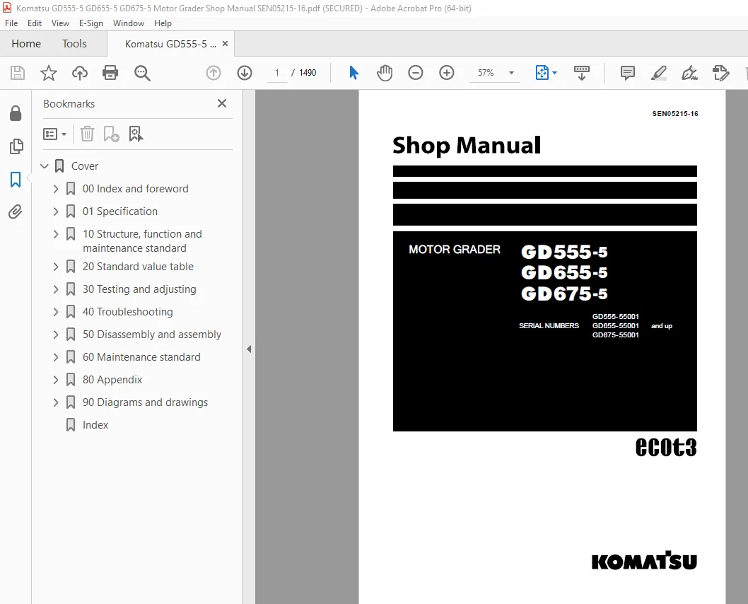
Komatsu GD555-5 GD655-5 GD675-5 Motor Grader Shop Manual SEN05215-16 – PDF DOWNLOAD
SERIAL NUMBERS
GD555-55001 and up
GD655-55001 and up
GD675-55001 and up
Description
Komatsu GD555-5 GD655-5 GD675-5 Motor Grader Shop Manual SEN05215-16 – PDF DOWNLOAD
FILE DETAILS:
Komatsu GD555-5 GD655-5 GD675-5 Motor Grader Shop Manual SEN05215-16 – PDF DOWNLOAD
Language : English
Pages : 1490
Downloadable : Yes
File Type : PDF
DESCRIPTION:
Komatsu GD555-5 GD655-5 GD675-5 Motor Grader Shop Manual SEN05215-16 – PDF DOWNLOAD
SERIAL NUMBERS
GD555-55001 and up
GD655-55001 and up
GD675-55001 and up
How to read the shop manual
Composition of shop manual
This shop manual contains the necessary technical information for services performed in a workshop. For
ease of understanding, the manual is divided into the following sections.
00. Index and foreword
This section contains table of contents, and safety and basic information. If any revision of the shop manual
is made, the LIST OF REVISED PAGES will be added.
01. Specification
This section explains the specifications of the machine.
10. Structure, function and maintenance standard
This section explains the structure and function of each component. It serves not only to give an understanding
of the structure, but also serves as reference material for troubleshooting.
20. Standard value table
This section explains the standard values for new machine and judgement criteria for testing, adjusting,
and troubleshooting. This standard value table is used to check the standard values in testing and adjusting
and to judge parts in troubleshooting.
30. Testing and adjusting
This section explains measuring instruments and measuring methods for testing and adjusting, and method
of adjusting each part. The standard values and judgment criteria for testing and adjusting are explained
in Testing and adjusting.
40. Troubleshooting
This section explains how to find out failed parts and how to repair them. The troubleshooting is divided
by failure modes. The “S mode” of the troubleshooting related to the engine may be also explained in the
Chassis volume and Engine volume. In this case, see the Chassis volume.
50. Disassembly and assembly
This section explains the special tools and procedures for removing, installing, disassembling, and assembling
each component, as well as precautions for them. In addition, tightening torque, and quantity and
weight of coating material, oil, grease, and coolant necessary for the work are also explained.
60. Maintenance standard
This section gives maintenance standard values of each component. The maintenance standard sub-section
explains the criteria and remedies for disassembly and service.
80. Appendix
The section explains the equipment which can not be included in the other sections. This section explains
the structure, function, testing, adjusting, and troubleshooting fo the equipment.
90. Diagrams and drawings (chassis volume)/Repair and replacement of parts (engine volume)
q Chassis volume
This section gives hydraulic circuit diagrams and electrical circuit diagrams.
q Engine volume
This section explains the method of remanufacturing and repairing engine and replacing parts.
TABLE OF CONTENTS:
Komatsu GD555-5 GD655-5 GD675-5 Motor Grader Shop Manual SEN05215-16 – PDF DOWNLOAD
SERIAL NUMBERS
GD555-55001 and up
GD655-55001 and up
GD675-55001 and up
Cover 1
00 Index and foreword 3
Table of contents 4
Table of contents 4
Foreword and general information 15
Safety notice 15
How to read the shop manual 20
Explanation of terms for maintenance standard 22
Handling of electric equipment and hydraulic components 24
Handling of connectors newly used for engines 33
How to read electric wire code 36
Precautions when carrying out work 39
Method of disassembling and connecting push-pull type coupler 42
Standard tightening torque table 45
List of Abbreviation 49
Conversion table 53
01 Specification 59
Specification drawing 61
Specifications 62
Weight table 68
Table of fuel, coolant and lubricants 69
10 Structure, function and maintenance standard 71
Engine and Cooling 74
Cooling system 74
Cooling fan pump 76
Power train system 84
Power train system drawing 84
Power train piping drawing 86
Transmission control 88
Torque converter 90
Transmission 94
Transmission control valve 116
ECMV 120
Main relief and torque converter relief valve 128
Front axle 130
Final drive (no differential specification) 134
Final drive (differential/ differential lock specification) 136
Differential lock solenoid valve 138
Tandem drive 140
Steering system 142
Steering piping diagram 142
Priority valve 144
Steering valve 150
Brake system 158
Brake hydraulic piping diagram 158
Brake valve 159
Slack adjuster 166
Accumulator (for brake) 168
Charge valve 169
Wheel brake 176
Parking brake and bank control valve 178
Parking brake 180
Undercarriage frame 182
Frame 182
Tire 184
Hydraulic system 186
Hydraulic system 186
Work equipment hydraulic piping diagram 190
Work equipment control 194
Hydraulic tank 196
Main pump 200
Power train pump 212
Control valve 214
CLSS 224
Functions and operation by valve 228
Hydraulic cylinder 238
Swivel joint 240
Pilot check valve 242
Accumulator (for blade) 250
Work equipment 252
Circle and drawbar 252
Blade 254
Lifter 256
Circle rotation motor 258
Circle rotation gear 260
Cab 262
Cab 262
Electrical ststem 264
Machine monitor 264
Automatic shift control system 268
Transmission controller 276
Engine controller 280
KOMTRAX system 284
Starting engine circuit 288
Stopping engine circuit 290
Preheating circuit 292
Sensor 294
Engine power mode select circuit 306
Cooling fan control function 308
20 Standard value table 313
Standard value table 315
Standard value table for engine 315
Standard value table for machine 317
30 Testing and adjusting 325
Precautions before work 328
Tools for testing, adjusting, and troubleshooting 330
Tools for testing, adjusting, and troubleshooting 330
Engine and cooling system 336
Testing engine speed 336
Testing intake air pressure (boost pressure) 338
Testing exhaust gas temperature 340
Testing exhaust gas color 342
Adjusting valve clearance 344
Testing compression pressure 346
Testing blowby pressure 349
Testing engine oil pressure 351
Handling fuel system device 352
Releasing remaining pressure from fuel system 353
Testing fuel pressure 354
Bleeding air from fuel circuit 355
Testing fuel circuit for leakage 356
Cylinder cut-out test mode 357
No injection cranking 358
Handling voltage circuit of engine controller 359
Checking muffler body and muffler stack for looseness and damage 360
Checking muffler function 361
Checking cylinder head and manifolds for looseness 362
Checking engine piping for damage and looseness 363
Checking fuel delivery, return rate and leakage 364
Replacing alternator belt 367
Checking and replacing auto-tensioner 369
Testing and adjusting air conditioner compressor belt tension [machines with air conditioner] 372
Power train 374
Testing power train oil pressure 374
Adjusting transmission speed sensor 386
Emergency escape method in case of transmission valve failure 390
Flushing torque converter and trasmission circuits 394
Testing and adjusting toe-in 396
Adjusting bearing preload 397
Testing and adjusting differential lock-up oil pressure [machine with differential lock-up] 398
Steering system 400
Testing and adjusting steering oil pressure 400
Testing steering cylinder oil leakage 401
Bleeding air from steering circuit 402
Brake system 404
Testing and adjusting brake oil pressure 404
Releasing remaining pressure from brake circuit 408
Bleeding air from brake circuit 409
Testing wheel brake disc wear 410
Testing and adjusting parking brake 412
Emergency release method of parking brake 414
Filling gas into brake accumulator 416
Hydraulic system 418
Testing and adjusting work equipment oil pressure 418
Testing and adjusting pump LS differential pressure 421
Testing lift arm lock cylinder circuit oil pressure [machine with bank cut] 423
Testing work equipment cylinder oil leakage amount 424
Bleeding air from work equipment circuit 427
Work equipment 428
Clearance adjustment of drawbar ball joint 428
Testing and adjusting circle guide clearance 429
Testing and adjusting slip clutch type circle rotator 431
Filling gas into blade accumulator [machine with blade accumulator] 433
Electrical system 434
Procedure for testing diodes 434
Special functions of machine monitor (EMMS) 435
Handling high voltage circuit of engine controller 484
How to start KOMTRAX terminal operations 486
Indicator lamps of KOMTRAX terminal 495
Preparation work for troubleshooting of electrical system 502
Pm clinic 504
Pm Clinic 504
40 Troubleshooting 513
Precautions before work 519
General information on troubleshooting 521
Points to remember when troubleshooting 521
Sequence of events in troubleshooting 522
Checks before troubleshooting 523
Classification and procedures for troubleshooting 543
Failure codes table 544
Failure and troubleshooting numbers 551
Information in troubleshooting table 553
Troubleshooting method for open circuit in wiring harness of pressure sensor system 555
Connector list and layout 557
Connection table for connector pin numbers 572
T- branch box and T- branch adapter table 608
Locations of fuses 611
Troubleshooting by failurecode 613
Failure code [1500LO] TORQUEFLOW transmission: Double engagement 613
Failure code [15G0MW] Transmission R clutch: Slip 614
Failure code [15H0MW] Transmission FH clutch: Slip 615
Failure code [15J0MW] Transmission FL clutch: Slip 615
Failure code [15K0MW] Transmission 1st clutch: Slip 616
Failure code [15L0MW] Transmission 2nd clutch: Slip 617
Failure code [15M0MW] Transmission 3rd speed clutch: Slip 618
Failure code [15N0MW] Transmission 4th clutch: Slip 619
Failure code [15SBL1] ECMV R clutch: Fill signal is ON when command signal is OFF 620
Failure code [15SBMA] ECMV R clutch: Malfunction 622
Failure code [15SCL1] ECMV FH clutch: Fill signal is ON when command signal is OFF 624
Failure code [15SCMA] ECMV FH clutch: Malfunction 626
Failure code [15SDL1] ECMV FL clutch: Fill signal is ON when command signal is OFF 628
Failure code [15SDMA] ECMV FL clutch: Malfunction 630
Failure code [15SEL1] ECMV 1st clutch: Fill signal is ON when command signal is OFF 632
Failure code [15SEMA] ECMV 1st clutch: Malfunction 634
Failure code [15SFL1] ECMV 2nd clutch: Fill signal is ON when command signal is OFF 636
Failure code [15SFMA] ECMV 2nd clutch: Malfunction 638
Failure code [15SGL1] ECMV 3rd clutch: Fill signal is ON when command signal is OFF 640
Failure code [15SGMA] ECMV 3rd clutch: Malfunction 642
Failure code [15SHL1] ECMV 4th clutch: Fill signal is ON when command signal is OFF 644
Failure code [15SHMA] ECMV 4th clutch: Malfunction 646
Failure code [15SJMA] ECMV lockup clutch: Malfunction 648
Failure code [15UONT] Inching clutch: Overheating 648
Failure code [2G42ZG] Front accumulater: Oil pressure drop 649
Failure code [2G43ZG] Rear accumulater: Pressure drop 649
Failure code [AA1ANX] Air cleaner: Clogging 650
Failure code [AB00L6] Alternator; Engine start and stop signals are not matched 652
Failure code [AB00MA] Alternator: Malfunction 654
Failure code: [B@BAZG] Derating in speed due to engine oil pressure drop 656
Failure code: [B@BCNS] Engine coolant overheat 656
Failure code: [B@CENS] Torque converter oil overheat 657
Failure code: [B@CKNS] Differential case: Overheat 658
Failure code: [B@HANS] Hydraulic oil: Overheating 660
Failure code [CA111] Engine controller internal error 662
Failure code [CA115] Engine Ne, Bkup speed sensor error 663
Failure code [CA122] Charge pressure sensor high error 664
Failure code [CA123] Charge pressure sensor low error 666
Failure code [CA131] Throttle sensor high error 668
Failure code [CA132] Throttle sensor low error 670
Failure code [CA144] Coolant sensor high error 672
Failure code [CA145] Coolant sensor low error 674
Failure code [CA153] Charge temperature sensor high error 676
Failure code [CA154] Charge temperature sensor low error 678
Failure code [CA155] Speed derating error by high charge temperature 680
Failure code [CA187] Sensor power supply 2 low error 682
Failure code [CA221] Atmospheric pressure sensor high error 684
Failure code [CA222] Atmospheric pressure sensor low error 686
Failure code [CA227] Sensor power supply 2 high error 688
Failure code [CA234] Engine overspeed 688
Failure code [CA238] Ne speed sensor power supply error 689
Failure code [CA271] IMV/IMA: Short circuit 690
Failure code [CA272] IMV/IMA open circuit 692
Failure code [CA322] Injector #1 (L#1) open/short 694
Failure code [CA323] Injector #5 (L#5) open/short 696
Failure code [CA324] Injector #3 (L#3) open/short 698
Failure code [CA325] Injector #6 (L#6) open/short 700
Failure code [CA331] Injector #2 (L#2) open/short 702
Failure code [CA332] Injector #4 (L#4) open/short 704
Failure code [CA342] Data compatibility error in engine controller 706
Failure code [CA351] Injector drive circuit error 707
Failure code [CA352] Sensor power supply 1 low error 708
Failure code [CA386] Sensor power supply 1 high error 709
Failure code [CA428] Water-in-fuel sensor high error 710
Failure code [CA429] Water-in-fuel sensor low error 712
Failure code [CA431] Idle validation switch error 714
Failure code [CA432] Idle validation action error 718
Failure code [CA435] Engine oil pressure switch error 721
Failure code [CA441] Power supply voltage low error 722
Failure code [CA442] Power supply voltage high error 724
Failure code [CA449] Common rail pressure high error 2 725
Failure code [CA451] Common rail pressure sensor high error 726
Failure code [CA452] Common rail pressure sensor low error 728
Failure code [CA488] Torque derating error by high charge temperature 730
Failure code [CA553] Common rail pressure high error 1 731
Failure code [CA559] Supply pump pressure low error 1 732
Failure code [CA689] Engine Ne speed sensor error 733
Failure code [CA731] Engine Bkup speed sensor phase error 735
Failure code [CA757] All continuous data lost error 736
Failure code [CA778] Engine Bkup speed sensor error 737
Failure code [CA1633] KOMNET (CAN communication) error 740
Failure code [CA2185] Throttle sensor power supply high error 742
Failure code [CA2186] Throttle sensor power supply low error 744
Failure code [CA2249] Supply pump pressure low error 2 746
Failure code [CA2311] Abnormality in IMV (IMA) solenoid 747
Failure code [CA2555] Intake heater relay open circuit 748
Failure code [CA2556] Intake heater relay short circuit 750
Failure code [D160KA] Backup lamp relay: Open circuit, hot short circuit in wiring harness 752
Failure code [D160KB] Backup lamp relay: Ground fault 754
Failure code [D19KKZ] Differential lock relay: Open circuit, ground fault 756
Failure code [D5ZHL6] C terminal signal: Signal does not match to actual engine state 758
Failure code [DAFRKR] CAN communication failure (monitor panel) 760
Failure code [DAQ0KK] Transmission controller: Power supply voltage low error (input) 762
Failure code [DAQOKT] Transmission controller: Non-volatile memory error 764
Failure code [DAQ2KK] Transmission controller load power line: Power supply voltage drop (input) 766
Failure code [DAQ9KQ] Transmission controller model selection: Model selection signal disagreement 768
Failure code [DAQRKR] Transmission controller CAN communication: Communication error 770
Failure code [DAQRMA] Transmission controller option setting: Malfunction 774
Failure code [DB2RKR] Engine controller CAN communication: Communication error 775
Failure code [DD1NLD] Fan reverse switch signal: Short circuit 782
Failure code [DD1PKB] RPM set switch power supply short circuit 784
Failure code [DD1QKB] RPM set mode switch short circuit 786
Failure code [DDB6L4] Transmission gearshift lever: Parking brake signal error 788
Failure code [DDTHKA] Fill switch for FH clutch: Open circuit 792
Failure code [DDTJKA] Fill switch for FL clutch: Open circuit 792
Failure code [DDTKKA] Fill switch for 1st clutch: Open circuit 793
Failure code [DDTLKA] Fill switch for 2nd clutch: Open circuit 793
Failure code [DDTMKA] Fill switch for 3rd clutch: Open circuit 794
Failure code [DDTNKA] Fill switch for R clutch: Open circuit 795
Failure code [DDTPKA] Fill switch for 4th clutch: Open circuit 796
Failure code [DF10KA] Transmission gearshift lever: No gear speed signal is input 797
Failure code [DF10L4] Transmission gearshift lever: Gear speed/travel direction signal error 801
Failure code [DGF1KX] Transmission oil temperature sensor: Input signal out of range 804
Failure code [DGH2KB] Hydraulic oil temperature sensor: Ground fault 806
Failure code [DGT1KX] Torque converter oil temperature sensor: Input signal out of range 808
Failure code [DGT7KB] Differential oil temperature sensor: Ground fault 810
Failure code [DJF1KA] Fuel level sensor: Open circuit 812
Failure code [DK70KX] Inching pedal angle sensor: Input signal out of range 814
Failure code [DKD0KX] Articulation angle sensor: Input signal out of range 816
Failure code [DLF1KA] Transmission input shaft speed sensor: Open circuit 818
Failure code [DLF1LC] Transmission input shaft speed sensor: Speed signal does not match 819
Failure code [DLF2KA] Transmission intermediate shaft speed sensor: Open circuit 820
Failure code [DLF2LC] Transmission intermediate shaft speed sensor: Speed signal does not match 821
Failure code [DLM3KA] Fan speed sensor: Open circuit 822
Failure code [DLM3LC] Fan speed sensor: Short circuit 823
Failure code [DLT3KA] Transmission output shaft speed sensor: Open circuit 824
Failure code [DV00KB] Buzzer: Short circuit 826
Failure code [DW4BKA] Parking brake solenoid valve: Open circuit 828
Failure code [DW4BKB] Parking brake solenoid valve: Short circuit 830
Failure code [DW7BKA] Fan reverse solenoid: Open circuit 831
Failure code [DW7BKB] Fan reverse solenoid: Short circuit 832
Failure code [DW7BKY] Fan reverse solenoid: Short circuit to power supply line 834
Failure code [DX16KA] Fan motor EPC solenoid: Open circuit 836
Failure code [DX16KB] Fan motor EPC solenoid: Short circuit 837
Failure code [DX16KY] Fan motor EPC solenoid: Short circuit to power supply line 838
Failure code [DXH1KA] Lockup ECMV solenoid: Open circuit 840
Failure code [DXH1KB] Lockup ECMV solenoid: Short circuit 841
Failure code [DXH1KY] Lockup ECMV solenoid: Short circuit to power supply line 842
Failure code [DXH2KA] FH clutch ECMV solenoid: Open circuit 844
Failure code [DXH2KB] FH clutch ECMV solenoid: Short circuit 845
Failure code [DXH2KY] FH clutch ECMV solenoid: Short circuit to power supply line 846
Failure code [DXH3KA] FL clutch ECMV solenoid: Open circuit 848
Failure code [DXH3KB] FL clutch ECMV solenoid: Short circuit 850
Failure code [DXH3KY] FL clutch ECMV solenoid: Short circuit to power supply line 852
Failure code [DXH4KA] 1st clutch ECMV solenoid: Open circuit 854
Failure code [DXH4KB] 1st clutch ECMV solenoid: Short circuit 856
Failure code [DXH4KY] 1st clutch ECMV solenoid: Short circuit to power supply line 858
Failure code [DXH5KA] 2nd clutch ECMV solenoid: Open circuit 860
Failure code [DXH5KB] 2nd clutch ECMV solenoid: Short circuit 862
Failure code [DXH5KY] 2nd clutch ECMV solenoid: Short circuit to power supply line 864
Failure code [DXH6KA] 3rd clutch ECMV solenoid: Open circuit 866
Failure code [DXH6KB] 3rd clutch ECMV solenoid: Short circuit 868
Failure code [DXH6KY] 3rd clutch ECMV solenoid: Short circuit to power supply line 870
Failure code [DXH7KA] R clutch ECMV solenoid: Open circuit 872
Failure code [DXH7KB] R clutch ECMV solenoid: Short circuit 873
Failure code [DXH7KY] R clutch ECMV solenoid: Short circuit to power supply line 874
Failure code [DXHHKA] 4th clutch ECMV solenoid: Open circuit 876
Failure code [DXHHKB] 4th clutch ECMV solenoid: Short circuit 878
Failure code [DXHHKY] 4th clutch ECMV solenoid: Short circuit to power supply line 880
Troubleshooting of electrical system (E-mode) 882
E-1 Engine does not start (starting motor does not turn) 882
E-2 Preheating does not work 888
E-3 When starting switch is turned to ON position, machine monitor displays nothing 893
E-4 When starting switch is turned to ON position, machine monitor does not reach standard screen 896
E-5 When starting switch is turned to ON position, caution monitor flashes or lights up, or machine monitor does not display correct screen 896
E-6 Emergency stop monitor lights up while engine is running 897
E-7 Speedometer or engine tachometer does not indicate correctly 901
E-8 Engine coolant temperature gauge does not indicate correctly 902
E-9 Articulation angle indicator does not indicate correctly 904
E-10 Torque converter oil temperature gauge does not indicate correctly 906
E-11 Fuel level gauge does not indicate correctly 908
E-12 Character display does not display correctly 910
E-13 Centralized warning lamp does not light up or does not go off 912
E-14 Alarm buzzer does not sound or does not stop sounding 914
E-15 Machine monitor mode selector switch does not work 916
E-16 Transmission mode does not switch 920
E-17 Engine mode does not switch 922
E-18 Differential lock function does not work or cannot be reset [for machine with differential lock specification] 924
E-19 Lift arm lock pin does not lock lift arm or does not unlock it [for machine with lift arm specification] 928
E-20 Blade accumulator function does not work or is not reset [for machine with blade accumulator specification] 930
E-21 Horn does not sound or does not stop sounding 934
E-22 Backup alarm does not sound or does not stop sounding 936
E-23 Headlamp, clearance lamp and tail lamp do not light up or do not go off 939
E-24 Working lamp does not light up or does not go off 946
E-25 Turn signal lamp and hazard lamp do not flash 952
E-26 Stop lamp does not light up or does not go off 958
E-27 Backup lamp does not light up or does not go off 960
E-28 Windshield wiper does not operate 962
E-29 Window washer does not operate 970
E-30 KOMTRAX system does not operate correctly 974
Troubleshooting of hydraulic and mechanical system (H-mode) 978
How to read troubleshooting matrix 978
H-1 Engine speed lowers significantly or engine stalls 984
H-2 Machine does not start 985
H-3 Gear is not shifted 986
H-4 Travel lacks speed or power 987
H-5 Torque converter lockup does not work or is not released 992
H-6 A large time lag results at start or in gear shift 993
H-7 Oil temperature of torque converter is high 998
H-8 Differential lock-up function does not work or is not released 1003
H-9 Steering lacks speed or power 1004
H-10 Steering wheel does not move 1005
H-11 Wheel brake does not work at all or sufficiently 1006
H-12 Wheel brake cannot be released or drags 1007
H-13 Parking brake does not work at all or insufficiently 1008
H-14 Parking brake (including emergency release system) cannot be released or drags 1009
H-15 All work equipment operation lacks speed or power 1010
H-16 Work equipment does not work at all 1011
H-17 Unusual noise comes out from around hydraulic pump 1012
H-18 Blade lift operation lacks speed or power 1013
H-19 Hydraulic drift of blade lift cylinders is large 1014
H-20 Drawbar side shift operation lacks speed or power 1015
H-21 Blade side shift operation lacks speed or power 1016
H-22 Power tilt operation lacks speed or power 1017
H-23 Articulate operation lacks speed or power 1018
H-24 Leaning operation lacks speed or power 1019
H-25 Hydraulic drift of leaning cylinders (leaning) is large 1020
H-26 Blade does not rotate 1021
H-27 Lift arm lock pin does not lock lift arm or does not unlock it (for machine with lift arm specification) 1022
H-28 Blade accumulator function does not work or cannot be released (for machine with blade accumulator float specification) 1023
H-29 Blade float function does not work or cannot be released 1024
H-30 Fan revolution is abnormal (Fan sound/vibration is abnormally large or engine overheats) 1025
Troubleshooting of engine (S-mode) 1026
Method of using troubleshooting chart 1026
S-1 Startability is poor 1030
S-2 Engine does not start 1031
S-3 Engine does not pick up smoothly 1034
S-4 Engine stops during operation 1035
S-5 Engine runs rough or is unstable 1036
S-6 Engine lacks power 1037
S-7 Exhaust smoke is black (incomplete combustion) 1038
S-8 Oil consumption is excessive (or exhaust smoke is blue) 1039
S-9 Oil becomes contaminated early 1040
S-10 Fuel consumption is excessive 1041
S-11 Oil is in coolant (or coolant spurts or coolant level goes down) 1042
S-12 Oil pressure drops 1043
S-13 Oil level rises (coolant or fuel in oil) 1044
S-14 Coolant temperature rises too high (overheating) 1045
S-15 Unusual noise is made 1046
S-16 Vibration is excessive 1047
50 Disassembly and assembly 1049
Precautions before work 1052
General information on disassembly and assembly 1054
How to read this manual 1054
Coating materials list 1056
Special tools list 1059
Sketches of special tools 1063
Engine and cooling system 1067
Removal and installation of fuel supply pump assembly 1067
Removal and installation of fuel injector assembly 1072
Removal and installation of cylinder head assembly 1082
Removal and installation of engine front oil seal 1100
Removal and installation of engine rear oil seal 1103
Removal and installation of cooling fan pump assembly 1107
Removal and installation of cooling fan and fan motor assembly 1109
Removal and installation of radiator assembly 1113
Removal and installation of aftercooler assembly 1117
Removal and installation of power train oil cooler assembly 1120
Removal and installation of fuel tank assembly 1123
Removal and installation of engine hood assembly 1127
Power train 1129
Removal and installation of engine and transmission/torque converter assembly 1129
Disassembly and assembly of engine and transmission/torque converter assembly 1137
Disassembly and assembly of torque converter assembly 1139
Disassembly and assembly of transmission assembly 1147
Removal and installation of tandem drive and final drive assembly 1185
Disassembly and assembly of tandem drive assembly 1189
Disassembly and assembly of final drive assembly 1194
Steering system 1213
Removal and installation of steering valve (Orbitrol) assembly 1213
Brake system 1220
Disassembly and assembly of wheel brake assembly 1220
Undercarriage and frame 1225
Removal and installation of center hinge pin 1225
Hydraulic system 1238
Removal and installation of hydraulic tank, battery and frame assembly 1238
Removal and installation of hydraulic tank assembly 1245
Removal and installation of control valve assembly 1252
Disassembly and assembly of control valve assembly 1258
Disassembly and assembly of hydraulic cylinder assembly 1261
Work equipment 1266
Removal and installation of blade assembly 1266
Removal and installation of circle drawbar assembly 1268
Removal and installation of circle rotation gear assembly 1271
Disassembly and assembly of circle rotation gear assembly 1273
Removal and installation of ripper assembly 1278
Cab and its attachments 1281
Removal and installation of operator cab assembly 1281
Removal and installation of floor frame assembly 1293
Removal and installation of operator cab glass (adhered glass) 1297
Removal and installation of air conditioner unit assembly 1307
Electrical system 1313
Removal and installation of engine controller assembly 1313
Removal and installation of machine monitor assembly 1315
Removal and installation of transmission controller assembly 1319
Removal and installation of KOMTRAX terminal assembly 1321
60 Maintenance standard 1323
Engine and Cooling 1326
Engine mount and transmission mount 1326
Cooling system 1328
Cooling fan motor 1330
Power train system 1334
Transmission control 1334
Torque converter 1336
Transmission 1338
Main relief valve and torque converter relief valve 1346
Front axle 1348
Final drive (no differential specification) 1352
Final drive (differential/ differential lock specification) 1354
Differential lock solenoid valve 1356
Tandem drive 1358
Brake system 1360
Slack adjuster 1360
Wheel brake 1362
Parking brake 1364
Hydraulic system 1366
Power train pump 1366
Control valve 1368
Hydraulic cylinder 1376
Work equipment 1378
Circle and drawbar 1378
Blade 1380
Lifter 1382
Circle rotation gear 1384
80 Appendix 1387
Precautions before work 1389
Air conditioner 1391
Precautions for refrigerant 1391
Air Conditioner Components 1392
Structure and Function of Refrigeration System 1394
Overview of Refrigeration System 1395
Air Conditioner Unit 1396
Compressor 1399
Condenser 1400
Receiver drier 1401
Air conditioner control panel 1402
Procedure for check and troubleshooting 1404
Circuit diagram and layout of connector pins 1406
System diagram 1408
Detail of air conditioner unit 1410
Parts and connectors layout 1412
Testing air leakage (ducts) 1414
Check with self-diagnosis (control panel display) 1415
Testing temperature control 1416
Testing Fresh/Recirc air changeover 1417
Testing evaporator temperature sensor 1418
Testing relays 1419
Testing blower amp 1420
Troubleshooting Chart 1 1421
Troubleshooting Chart 2 1423
Information in troubleshooting table 1425
Troubleshooting for power supply system (Air conditioner does not operate) 1426
Troubleshooting of compressor and refrigerant system (Air is not cooled) 1428
Troubleshooting for blower motor system (Air does not come out or air flow is improper) 1432
Troubleshooting for temperature control 1434
Troubleshooting for FRESH/RECIRC air changeover 1436
Troubleshooting with gauge pressure 1438
Connection of service tool 1440
Precautions for disconnecting and connecting air conditioner piping 1442
Handling compressor oil 1444
90 Diagrams and drawings 1447
Hydraulic diagrams and drawings 1449
Symbols used in hydraulic circuit diagrams 1449
Hydraulic circuit diagram 1451
Power train hydraulic circuit diagram 1455
Differential hydraulic circuit diagram 1457
Electrical diagrams and drawings 1459
Symbols used in electric circuit diagrams 1459
Electrical circuit diagram 1463
Index 1483
IMAGES PREVIEW OF THE MANUAL:
S.V 17/12/24



