Komatsu HB215LC-2 Hydraulic Excavator Shop Manual K60001 PDF
$39.95
Komatsu HB215LC-2 Hydraulic Excavator Shop Manual K60001 – PDF DOWNLOAD
- HB215LC-2 K60001 and up
Description
Komatsu HB215LC-2 Hydraulic Excavator Shop Manual K60001 – PDF DOWNLOAD
FILE DETAILS:
Komatsu HB215LC-2 Hydraulic Excavator Shop Manual K60001 – PDF DOWNLOAD
Language : English
Pages : 2101
Downloadable : Yes
File Type : PDF
IMAGES PREVIEW OF THE MANUAL:
TABLE OF CONTENTS:
Komatsu HB215LC-2 Hydraulic Excavator Shop Manual K60001 – PDF DOWNLOAD
- HB215LC-2 K60001 and up
00 Index and foreword . 1
Index (ALL-0310-001A00A) 2
Foreword, safety and general information (ALL-0370-001A00A) . 16
Important safety notice (Hybrid) (HB380-1120-012A00A) . 16
Important safety precautions 16
Precautions peculiar to hybrid machine 16
Safety points . 16
General precautions . 17
Precautions for preparatory work 17
Precautions during work . 17
Precautions for slinging work and making signals 18
Precautions for using mobile crane 19
Precautions for using overhead travelling crane . 19
Selecting wire ropes 20
Precautions for disconnecting air conditioner piping 20
Precautions for air conditioner piping 20
Prevent fire (ALL-0000-17BK03A) . 21
Actions if fire occurs (ALL-0000-17AK01A) . 23
Dispose of waste materials (ALL-0000- 99AK02A) 24
How to read the shop manual (ALL-0320-010A01A) 25
Composition of shop manual 25
Symbol 26
Unit 26
Explanation of terms for maintenance standard (ALL-0330-006A01A) 27
Standard dimension and tolerance 27
Standard clearance and standard value . 27
Standard interference . 27
Repair limit and allowable value or allowable dimension . 28
Allowable clearance . 28
Allowable interference 28
Handling equipment of fuel system devices (PC-AD00-2A4K00A) . 29
Use care for working environment 29
Sealing openings 29
How to clean parts when dirt is stuck . 29
Precautions for replacing fuel filter cartridge . 29
Handling of intake system parts (PC220-A900-2A4K00A) 30
Be careful of working environment . 30
Sealing openings 30
Handling of hydraulic equipment (ALL-C000-2A4P01A) 31
Be careful of working environment . 31
Disassembly and maintenance work in the field . 31
Plugging of opening (prevention of flowing out of oil) 31
Preventing intrusion of foreign materials during refilling operations . 31
Replacing hydraulic oil while its temperature is high . 31
Flushing operations . 32
Cleaning operations . 32
Method of disconnecting and connecting of push-pull type coupler (ALL- C930-001P00A) 33
Type 1 (ALL-C930-925P01A) . 33
Disconnection . 33
Connection 33
Type 2 (ALL-C930-925P02A) . 34
Disconnection . 34
Connection 34
Type 3 (ALL-C930-925P03A) . 35
Disconnection . 35
Connection 35
Handling of electrical equipment (ALL-E000-2A4P01A) . 36
Precautions for handling electric equipment . 36
Handling wiring harnesses and connectors 36
Main failures occurring in wiring harness . 36
Removing, installing, and drying connectors and wiring harnesses 37
Handling of connectors used on engine . 40
Slide, lock type 40
Pull lock type 41
Push lock type 41
Turn-housing type (Round green connector) . 42
Handling controller . 43
Precautions for troubleshooting electrical circuits . 43
How to read electric wire code (Hybrid) (HB380-E500-030P00A) 44
Type, symbol, and material 44
Dimensions 46
Colour codes table 49
Types of circuits and colour codes 49
Precautions when performing operation (ALL-1160-927A00A) 51
Precautions for removal and disassembly work 51
Precautions for installation and assembly work 55
Precautions at the time of completing work 56
Practical use of KOMTRAX (ALL-Q210-13VK00A) . 57
Merit of using KOMTRAX 57
How to use KOMTRAX practically 57
How to operate KOMTRAX 57
Handling hybrid components and high voltage wiring harness (HB380-PQJE- 015K00A) 58
Precautions for maintenance on hybrid system (HB380-PQG9-012K05A) . 58
Precautions for high voltage and high temperature (HB380-PQJE-012K00A) 59
Precautions for normal testing and adjusting (HB380-PQG9-012K01A) . 60
Procedure for removing hybrid devices and high-voltage wirings and testing connection terminals . 60
Restoration . 60
Precautions when machine tips over and hybrid component damages (HB380-PQG9-012K02A) 61
Precautions for submersion (HB380-PQG9- 012K03A) 62
Precautions for cold season (HB380-PQG9- 012K04A) . 63
Standard tightening torque table (ALL-M140-03BP01A) . 64
Table of tightening torque for bolts and nuts . 64
Table of tightening torque for O-ring boss piping joints 67
Table of tightening torque for O-ring boss plugs 68
Table of tightening torque for hose (taper seal type and face seal type) 69
Table of tightening torque for face seal joints . 70
Tightening torque table for bolts and nuts on 102,107 and 114 series engines 70
Tightening torque table for 102, 107, and 114 series engines (joint bolts) 70
Tightening torque table for tapered screws on 102,107, and 114 series engines (National taper pipe thread (NPT)) 71
List of abbreviation (ALL-0360-005A00A) . 72
List of abbreviations used in the shop manual . 72
List of abbreviations used in the circuit diagrams 76
Conversion table (ALL-2150-931A00A) . 78
Method of using the conversion table 78
Millimetres to inches . 78
Millimetres to inches . 79
Kilograms to pounds . 79
l to U.S. Gallons . 79
l to U.K. Gallons . 81
kgm to ft.lb 81
kg/cm2 to lb/in22 . 83
Temperature . 84
01 Specification 87
Table of contents (ALL-0310-002A00A) 88
Specifications (ALL-2111-001A00A) . 89
Specification drawing (ALL-2110-001A00A) 89
HB215LC-2 (HB205-2110-931A07A) 89
Working range drawings (ALL-2110-001A02A) . 91
HB215LC-2 (HB205-2110-931A08A) 91
Specifications (ALL-2111-001A01A) . 92
HB215LC-2 (HB205-2111-931A03A) 92
Weight table (ALL-2120-001A01A) . 97
HB215LC-2 (HB205-2120-931A03A) 97
Table of fuel, coolant, and lubricants (HB205-RA19-05AK03A) . 99
10 Structure and function . 101
Table of contents (ALL-0310-002A00A) 102
Engine and cooling system (ALL-R401-001K00A) 104
Engine related parts (HB205-A001-041K00A) . 104
VFT (ENG95-AA10-041K00A) 105
Specifications (PC160-AA10-030K00A) . 107
Operation (ENG95-AA10-044K00A) 108
EGR system piping drawing (PC160-A9J0-04DK00A) 109
Function (ENG95-A9J0-042K00A) . 109
EGR system circuit diagram (ENG107-A9J0-052K01A) 110
Operation (ENG95-A9J0-044K00A) 110
EGR valve (ENG95-A9K1-041K00A) 111
Structure . 111
Operation (ENG95-A9K1-044K00A) 111
EGR cooler (PC160-A9L0-041K00A) . 113
Operation (ENG95-A9L0-044K00A) 113
KCCV layout drawing (HB205-A180-04DK00A) 114
Operation (PC160-A180-044K00A) 114
KCCV ventilator (HB205-A18H-041K00A) 116
Function (PC160-A18H-042K00A) . 116
Operation (ENG107-A18H-044K00A) . 117
CDR valve (PC160-A18A-041K00A) 118
KDOC muffler (PC160-A9H2-041K00A) . 119
Structure . 119
Function (PC160-A9H2-042K00A) . 119
Cooling system (HB205-B000-041K00A) . 120
Specifications (HB205-B000-030K00A) . 121
Hybrid system (HB380-PQG9-001K00A) 122
Outline of hybrid system (HB205-PQG9-04AK00A) . 122
Low fuel consumption by hybrid system . 122
Configuration of hybrid system (HB380-PQG9-041K00A) . 123
Protective function of hybrid component (HB380-PQJL-042K01A) 124
Function 124
Conditions for stopping whole hybrid system . 125
Protection function for workers when disassembling hybrid component (HB205-PQJK-042K00A) 126
Function 126
One-touch connector . 127
Cooling system of hybrid component (HB380-PQG9-041K02A) . 128
Interlock function (HB205-PQJM-042K00A) . 129
Function 129
Motor-generator (HB205-PQH3-041K00A) 130
Specifications (HB205-PQH3-030K00A) . 130
Function (HB380-PQH3-042K00A) . 131
Electric swing motor (HB205-PQHH-041K00A) . 132
Specifications (HB205-PQHH-030K00A) . 132
Function (HB380-PQHH-042K00A) . 133
Electric control unit (HB205-PQGA-041K00A) 134
Specifications (HB205-PQGA-030K00A) . 134
Function (HB380-PQGA-042K00A) . 135
High voltage wiring harness (power cable) (HB205-PQJF-041K00A) 136
Structure . 136
Function (HB380-PQJF-042K00A) . 136
Water pump (HB205-PQGV-041K00A) . 137
Specifications (HB205-PQGV-030K00A) . 137
Function (HB380-PQGV-042K00A) . 138
Power train (ALL-C100-001K00A) 139
Power train system (HB205-C100-041K00A) . 139
Swing circle (HB205-J110-041K00A) . 141
Specification (PC200_10-J110-030K00A) . 141
Swing machinery with swing brake (HB205-J130-041K00A) . 142
Specifications (HB205-J110-030K00A) . 143
Final drive (HB205-DF10-041K00A) 144
Specifications (HB205-DF10-030K00A) . 145
Undercarriage and frame (ALL-DT00-001K00A) 146
Track frame and idler cushion (HB205-DT20-041K01A) 146
Specifications (HB205-DT20-030K01A) . 146
Hydraulic system (ALL-C000-001K00A) . 147
Hydraulic component layout (HB205-C000-04DK00A) . 147
Valve control (PC-PK01-041K00A) . 149
Hydraulic tank (HB205-PM30-041K00A) . 151
Specifications (PC220-PM30-030K00A) . 151
Oil filler cap (PC-AD1C-041K00A) 152
Prevention of negative pressure in tank . 152
Prevention of pressure rise in tank . 152
CLSS (ALL-PNJ1-001K00A) . 153
Structure of CLSS (ALL-PNJ1-041K00A) 153
Features 153
Configuration . 153
Basic principle . 154
Pump swash plate angle control 154
LS differential pressure (dPLS) and pump swash plate angle 155
Pressure compensation control . 155
System diagram 156
Main pump (PC220-C200-041K00A) 158
Outline . 161
Function 161
Structure . 161
Operation (PC220-C200-044K00A) 161
Control of discharged volume 162
LS valve (PC-C2J0-041K00A) 164
Function (PC-C2J0-042K00A) 164
Operation (PC-C2J0-044K00A) . 165
When control valve is in “NEUTRAL” position . 165
When pump delivery is increased . 167
When pump discharged volume is decreased 168
When servo piston is balanced . 169
PC valve (PC-C2K0-041K00A) 170
Function (PC-C2K0-042K00A) 170
Operation (PC-C2K0-044K00A) . 171
When the pump controller is normal 171
When load on the actuator is small and pump pressures (PP1) and (PP2) are low . 171
Actuation of PC-EPC valve solenoid (1) 171
Action of spring 172
When load on the actuator is large and pump pressures (PP1) and (PP2) are high 173
Outline . 173
Operation . 174
When the pump controller malfunctions and the emergency pump drive switch is at “ON” position . 175
When load on the main pump is small . 175
When load on the main pump is large . 176
LS-EPC valve (HB380-C2M0-041K00A) . 178
Structure . 179
Function (HB380-C2M0-042K00A) . 179
Operation (HB205-C2M0-044K00A) 179
When signal current is zero (coil de-energized) . 180
When signal current is minute (coil is energized) . 181
When signal current is maximum (coil is energized) 182
PC-EPC valve (HB380-C2N0-041K00A) . 183
Structure . 184
Function (HB380-C2N0-042K00A) . 184
Operation (HB205-C2N0-044K00A) 184
When signal current is zero amp. (coil is de-energized) . 185
When signal current is minute (coil is energized) . 186
When signal current is maximum (coil is energized) 187
Pilot oil filter 188
For breaker . 188
Specifications 188
Control valve (HB205-C030-041K01A) 189
General view 189
Sectional view 191
Arm valve . 195
R.H. travel valve . 196
Boom valve 197
L.H. travel valve . 198
Bucket valve 198
Service valve 1 . 199
Service Valve 2 . 199
Structure . 200
Hydraulic circuit diagram and names of valves (HB205-C030-054K01A) 201
Unload valve (PC220-PQD5-041K00A) . 203
Function (PC220-PQD5-042K00A) . 203
Operation (ALL-PQD5-044K00A) 203
Operation of relief valve . 203
Introduction of LS pressure (PC220-C2A4-041K00A) 204
Function (HB205-C2A4-042K00A) . 204
Operation (PC220-C2A4-044K00A) 205
LS bypass plug (HB205-PNSH-041K01A) . 206
Function (ALL-PNSH-042K00A) . 206
Pressure compensation valve (HB205-L6D0-040K00A) 207
During independent operation and at Max. high load pressure . 207
Function 207
Unit type pressure compensation valve . 207
When compensated 208
Function 208
Operation . 208
Surface area ratio of pressure compensation valve . 209
Function 209
Shuttle valve in pressure compensation valve (PC220-L6D3-040K00A) . 210
When holding pressure at port (A) becomes higher than LS pressure in spring chamber (B) . 210
Operation . 210
When travelling . 211
Structure . 211
Boom regeneration circuit (PC220-L511-040K00A) 212
When cylinder head pressure is lower than bottom pressure (hydraulic drift, etc.) . 212
Function 212
Operation . 212
When cylinder head pressure is higher than bottom pressure (digging operation, etc.) 213
Function 213
Arm regeneration circuit (PC220-L911-040K00A) . 214
When cylinder head pressure is higher than bottom pressure 214
Function 214
Operation . 214
When cylinder head pressure is lower than bottom pressure . 215
Function 215
Merge-divider valve (HB205-PP30-040K00A) 216
When the pumps are merged [When merge-divider selector signals (IS1) and (IS2) are OFF] . 216
Function 216
Operation . 216
When the pumps are divided [When merge-divider selector signals (IS1) and (IS2) are ON] . 217
Operation . 217
Self-pressure reducing valve (PC220-PL30-042K00A) . 218
Function 218
Operation (ALL-PL30-044K00A) 218
When engine is stopped 218
When load pressure (P2) is low 220
When load pressure (P2) is high . 221
When abnormally high pressure is generated 222
Travel junction valve (PC220-C6C0-042K00A) 223
Function 223
Operation (ALL-C6C0-044K00A) 224
When pilot pressure (PST) is shut off (travel junction) . 224
When pilot pressure (PST) is supplied (travel independent) 225
Travel PPC shuttle valve (PC220-C6V1-042K00A) . 226
Function 226
Operation (ALL-C6V1-044K00A) 226
When travel is neutral 226
When operating travel . 227
Hydraulic drift prevention valve 228
(For the boom and arm) 228
Function 229
Operation . 229
If the piping is burst 229
Arm hydraulic drift prevention valve (HB205-L9K0-041K00A) . 233
Function 233
Operation (HB205-L9K0-044K00A) 233
In arm “OUT” operation 233
When arm is in “NEUTRAL” 234
In arm “IN” operation . 235
Safety valve (PC200_10-L9K2-042K00A) 236
Function 236
Operation (PC220-L9K2-044K00A) 236
Operation when abnormally high pressure is generated 236
Arm quick return valve (PC220-L9K1-042K00A) . 238
Function 238
Operation (HB205-L9K1-044K00A) 238
In arm “”OUT“” operation 238
When arm is in “NEUTRAL” 239
Variable back pressure valve (HB205-PQ81-042K00A) . 240
Function 240
Operation (HB205-PQ81-044K00A) 240
When engine is stopped 240
When engine is running (for travel operation) . 241
When engine is running (for other than travel operation) 242
Main relief valve (HB205-PQ91-041K00A) 243
Function (PC220-PQ91-042K00A) . 243
Operation (PC-PQ91-044K00A) . 243
When pilot pressure (P) is shut off (low pressure setting) 243
When pilot pressure (P) is supplied (high pressure setting) . 243
2-stage suction-safety valve (PC220-PQJ2-041K00A) . 244
[Installed to port (B) of the service valve] 244
Function (HB205-PQJ2-042K00A) . 244
Operation (ALL-PQJ2-044K00A) 244
When pilot pressure (P) is shut off (high pressure setting) . 244
When pilot pressure (P) is supplied (low pressure setting) 245
Travel motor (HB205-C400-041K00A) . 246
L.H. travel motor . 246
R.H. travel motor . 246
Specifications (HB205-C400-030K00A) . 248
Operation of travel motor (HB205-C400-044K00A) 249
Travel speed at low-speed setting (motor swash plate angle is at maximum) . 249
Travel speed at high-speed setting (motor swash plate angle is at minimum) 250
Parking brake operation (HB205-C4A0-044K00A) 251
When starting travel 251
When stopping travel 252
Brake valve (ALL-C4Q0-041K00A) 253
Counterbalance valve (PC220-C4N0-042K00A) . 253
Function 253
Operation (PC-C4N0-044K00A) . 253
Operation when pressurized oil is supplied 254
Braking while travelling downhill . 256
Suction safety valve (PC220-C660-042K00A) . 256
Function 256
Operation (PC-C660-044K00A) . 256
When machine stops travelling (or travelling downhill) (when motor rotating clockwise) 257
When starting travel (or when travelling normally) 258
PPC valve (ALL-CW10-001P00A) 259
Work equipment and swing PPC valve (PC-PL28-041K00A) 259
Operation (PC-PL28-044K00A) . 262
When valve is in neutral 262
When valve is in fine control range . 263
(neutral to fine control range) . 263
When valve is in fine control range . 264
(when control lever is returned) 264
When control lever is fully operated 265
Travel PPC valve (PC-C6V0-041K00A) 266
Operation (PC-C6V0-044K00A) . 267
When valve is in neutral 268
When valve is in fine control range . 269
(neutral to fine control range) . 269
When valve is in fine control range . 270
(when control lever is returned) 270
When control lever is fully operated 271
1st-line attachment PPC valve (with EPC valve) (PC200_10-PL29-041K00A) 272
EPC valve (PC200_10-PL2B-041K00A) . 274
Function (PC-PL2B-042K00A) 275
Operation (PC200_10-PL2B-044K00A) . 276
When signal current is zero amp. (coil is de-energized) . 276
When signal current is minute (coil is energized) . 278
When signal current is maximum (coil is energized) 279
2nd-line attachment PPC valve (PC-PL2A-041K00A) . 280
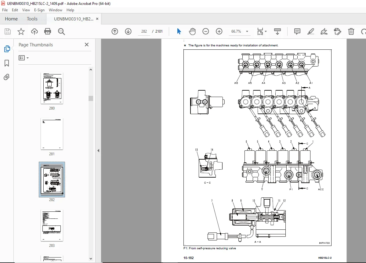
Solenoid valve (HB205-PQPT-041K00A) . 282
Operation (ALL-PQPT-044K00A) 283
Operation of check valve 283
Operation of solenoid valve . 284
When solenoid valve is “de-energized” (circuit is disconnected) . 284
When solenoid valve is “energized” (circuit is interconnected) 284
Attachment circuit selector valve (for low pressure circuit) (PC-PQJ3-041K00A) 285
Function (PC220-PQJ3-042K00A) . 285
Operation (PC-PQJ3-044K00A) . 286
When attachment other than breaker is installed . 286
When breaker is installed . 287
Centre swivel joint (HB205-J8E0-041K00A) 288
Accumulator (PC-PL40-001K00A) . 290
PPC accumulator (PC-PL40-041K00A) . 290
Specifications (PC-PL40-030K00A) 290
Function (PC-PL40-042K01A) 290
ATT EPC valve assembly 292
ATT EPC valve (1) . 293
Shuttle valve (3 and 4) . 293
Return oil filter . 294
For breaker . 294
Specifications 294
Quick coupler control valve . 295
Specification . 295
Operation . 295
System diagram 296
Function 297
Work equipment (ALL-L000-001K00A) . 298
Work equipment (PC-L410-041K00A) 298
Work equipment shim (PC220-L413-040K00A) 299
Outline . 299
Function 299
Bucket play adjustment shim (PC220-LBKB-040K00A) 300
Outline . 300
Cab and its attachments (ALL-K000-001K00A) 301
Cab mount and cab tipping stopper (PC-K138-041K00A) . 301
Structure . 301
ROPS cab (PC-K000-041K00A) 302
Function (PC220-K000-042K00A) . 302
Electrical system (ALL-RA1D-001K01A) 303
Electrical control system (PC220-C050-001K00A) 303
General system drawing (HB205-C050-051K01A) . 303
Engine control function (PC220-AK60-042K00A) 306
Function 306
Starting the engine . 306
Engine speed control 307
Engine stop . 307
Stopping the engine with engine shutdown secondary switch . 307
Engine and pump combined control function (HB205-C3W0-042K01A) 308
Input/output signal . 309
Function 310
Control method in each mode . 311
P, E, ATT/P, and ATT/E modes 311
B and L mode 313
Control function when travelling 315
Pump and valve control function (HB205-C3W1-042K00A) 316
Input/output signal . 317
Function 318
LS control function . 318
Cut-off function (P, E, ATT/P, and ATT/E mode) 318
Cut-off function (B and L mode) . 319
2-stage relief function . 319
Variable back pressure function . 319
One-touch power maximizing function (HB205-PT23-042K00A) 320
Input/output signal . 321
Function 321
Auto-deceleration function (HB205-AF60-042K00A) . 322
Input/output signal . 322
Function 323
Operation . 323
When control lever is in operation 323
Engine speed when auto-deceleration is operated . 323
Engine automatic warm-up function (HB205-AP13-042K00A) 324
Input/output signal . 325
Overheat prevention function (HB205-B717-042K00A) . 327
Overheat prevention function of hybrid component 328
Turbocharger protection function (HB205-AA90-042K00A) . 329
Swing control function (HB205-JA01-042K00A) . 330
Input/output signal . 330
Function 331
Swing parking brake release function 332
Quick warm-up function 333
Travel control function (HB205-C7H1-042K02A) 334
Input/output signal . 334
Travel speed selector function 335
Pump control function when travelling . 335
Travel junction function 336
PPC lock function (PC-PX16-042K00A) . 337
Function 337
System operating lamp function (HB205-AW1Q-042K01A) . 338
Function 338
ON/OFF of system operating lamp . 338
Attachment flow control function 340
1 Attachment circuit 340
2 Attachment circuit 341
Input and output signals 342
Function (1 Attachment) . 342
Function (2 Attachment) . 342
Auto idle stop function (HB205-AF87-042K01A) 343
Function 343
System component parts (ALL-RA1C-001K00A) . 348
Engine controller (PC220-AP70-041K00A) 348
Input and output signals of engine controller (HB205-AP70-03CK00A) 348
DRC26-60P(1)[ECM J1(CN-CE01)] . 348
DRC26-60P(2)[ECM J2(CN-CE02)] . 350
DRC26-60P(3)[CN-CE03] . 352
Pump controller (PC-C3V1-041K00A) . 353
Input and output signals of pump controller (HB205-C3V1-03CK00A) 354
Inverter (HB205-PQGK-041K00A) . 358
Input and output signals of hybrid controller (HB205-PQGK-03CK00A) 358
Fuel control dial (PC-AGJ7-041K01A) . 360
Function (PC-AGJ7-042K00A) 361
Resister for PC-EPC valve (PC200_10-C3VR-041K00A) . 361
Specifications (PC220-C3VR-030K00A) . 362
Function (PC-C3VR-042K00A) 362
CAN terminating resistor (PC220-Q2V1-041K00A) . 362
Specifications (PC220-Q2V1-030K00A) . 362
Function (PC220-Q2V1-042K00A) . 362
Engine oil pressure switch (PC-ABK6-041K00A) 363
Specifications (PC220-ABK6-030K00A) . 363
Function (PC-ABK6-042K00A) 363
PPC oil pressure switch (PC-E610-041P00A) . 363
Specifications (PC220-E610-030P00A) . 364
Function (PC220-E610-042P00A) . 364
Machine monitor system (HB205-Q170-042K00A) . 365
Input/output signal . 365
Function 366
Machine monitor (PC-Q180-042K01A) . 366
Function 366
Precautions on the machine monitor display 366
Input and output signals (PC-Q180-03CK00A) 367
Display (HB205-Q1LA-042K01A) 369
Hybrid temperature gauge (detailed) . 379
Switches (HB205-Q1C0-042K01A) . 380
Guidance icon and function switch (HB205-Q1C1-042K01A) 382
Operator mode functions (HB205-Q193-042K02A) 386
Service mode functions (HB205-Q194-042K01A) . 387
KOMTRAX system (PC-Q210-042K00A) 389
KOMTRAX terminal (PC220-Q220-042K00A) . 389
Input and output signals (PC220-Q220-03CK00A) . 390
Function (PC-Q220-042K00A) 391
Sensor (ALL-E700-001P00A) . 392
Ambient pressure sensor (ENG-AAP2-041K00A) 392
Function (HB205-AAP2-042K00A) . 392
Output characteristics 392
Charge (boost) pressure and temperature sensor (ENG-AAM7-041K00A) . 393
Function (ENG-AAM7-042K00A) . 393
Output characteristics 393
Coolant temperature sensor (ENG-BA87-041K00A) . 394
Function (ENG-BA87-042K00A) . 394
Ne (crankshaft) speed sensor (ENG-AG42-041K00A) . 395
Function (ENG-AG42-042K00A) . 395
Bkup (camshaft) speed sensor (ENG-AG62-041K00A) . 396
Function (ENG-AG62-042K00A) . 396
Common rail pressure sensor (ENG-AE28-041K00A) 397
Function (ENG-AE28-042K00A) . 397
Exhaust manifold pressure sensor (ENG-AAN5-041K00A) . 398
Function (ENG-AAN5-042K00A) . 398
EGR orifice temperature sensor (ENG-A9U5-041K00A) . 399
Function (ENG-A9U5-042K00A) . 399
VFT motor (with built-in position sensor) (ENG95-AA56-041K00A) 400
Function (ENG95-AA56-042K00A) . 400
EGR valve (with built-in position sensor) (ENG95-AA57-041K00A) 401
Function (ENG95-AA57-042K00A) . 401
Mass air flow and temperature sensor (ENG-A96H-041K00A) . 402
Function (ENG-A96H-042K00A) . 402
Crankcase pressure sensor (ENG-A18C-041K00A) 403
Function (ENG-A18C-042K00A) . 403
Engine oil level sensor (ENG-AB45-041K00A) 404
Function (ENG-AB45-042K00A) . 404
Fuel level sensor (PC-AD41-041K00A) . 405
Function (PC-AD41-042K00A) 405
Coolant level sensor (PC-B252-041K00A) 406
Function (PC-B252-042K00A) 406
Hydraulic oil temperature sensor (PC-PMT1-041K00A) 407
Function (PC-PMT1-042K00A) 407
Front pump oil pressure sensor (PC-C3W4-041K00A) 408
Function (PC-C3W4-042K00A) 408
Output characteristics 408
Rear pump oil pressure sensor (PC-C3W5-041K00A) . 409
Function (PC-C3W5-042K00A) 409
Output characteristics 409
PPC oil pressure sensor (PC-E720-041P00A) . 410
Function (HB205-E720-042P00A) . 410
Output characteristics 410
Air cleaner clogging sensor (PC-A968-041K01A) . 411
Function (HB205-A968-042K00A) . 411
Front pump swash plate sensor (PC-C3W9-041K00A) . 412
Function (PC200_10-C3W9-042K00A) 412
Output characteristics 412
Rear pump swash plate sensor (PC-C3WB-041K00A) 414
Function (PC200_10-C3WB-042K00A) 414
Output characteristics 414
Water-in-fuel sensor (PC-AEB3-041K00A) 416
Function (PC-AEB3-042K00A) 416
Quick coupler low pressure warning switch sensor 416
Specification . 416
Function 416
Auto grease pressure switch . 417
Specification . 417
Function 417
PPC levers 418
LH PPC lever 418
PPC levers 419
RH PPC lever 419
Auto grease system 420
Outline of auto grease system . 420
Assembly 420
Components 421
The minimum-level switch 421
The test push-button 421
(b) Distributor Blocks and Metering Units . 422
(c) Grease Pressure Switch 423
(d) The Display . 423
The greasing cycle 423
Greasing Cycle A 423
The re-grease phase . 424
The pressure decrease phase . 424
The pause phase . 424
Greasing cycle B 424
Introduction 424
(a) Pump unit . 424
The grease reservoir and the grease follower piston . 425
The 5/2 Magnetic Valve 426
(b) Metering units 426
Phase 1 . 426
Phase 2 . 427
Phase 3 . 427
Phase 4 . 428
(c) Grease pressure switch 429
Phase 1 . 429
Phase 2 (pumping phase A) . 429
Phase 3 (pumping phase B) . 430
(d) Control unit 430
The length of the greasing cycles . 430
Maximum length of the pumping phase . 431
Length of the re-grease and pressure decrease phases 431
Reaction of the system to grease pressure malfunctions 431
Display . 432
20 Standard value tables 435
Table of contents (ALL-0310-002A00A) 436
Standard service value table (ALL-A000-001K00A) . 437
Standard value table for engine (HB205-A000-033K01A) 437
Standard value table for machine (HB205-0000-033K01A) . 439
HB215LC-2 . 439
Engine speed 439
Control valve spool stroke 439
Travel of control lever . 440
Operating effort of control lever and pedal . 440
Hydraulic pressure 441
Swing . 444
Travel 445
Work equipment 446
Oil leakage . 448
Performance of combined operation . 449
Pump swash plate sensor . 449
Characteristics of PC flow control 449
Main pump . 450
Water pressure 451
Posture of machine for measuring performance and measurement procedure (PC220_10-0000-321K00A) 451
Standard value table for electrical system (D155-E000-001P00A) 457
Controller (HB205-RA1E-033K00A) . 457
Engine control (HB205-AG10-033K00A) . 459
Machine control (HB205-E000-033P00A) 464
Machine monitor (HB205-Q170-033K00A) 468
30 Testing and adjusting 469
Table of contents (ALL-0310-002A00A) 470
Related information on testing and adjusting (ALL-3831-001A00A) . 471
Tools for testing and adjusting (HB205-5320-304A00A) 471
Sketch of tools for testing and adjusting (PC300-3531-061A00A) 476
Engine and cooling system (ALL-R401-001K30A) 478
Testing engine speed (PC200_10-A000-360K00A) 478
Testing (HB205-A000-388K01A) 478
Testing low idle speed 478
Testing high idle speed (at P mode with auto- deceleration OFF) . 478
Testing high idle speed (at B mode with travel lever fine control) 478
Measuring engine speed at 2-pump relief . 478
Checking speed (around rated speed) at 2-pump relief + one-touch power maximizing function 479
Measuring the engine speed when auto- deceleration is activated . 479
Testing boost pressure (PC160-A900-360K01A) . 480
Testing (HB205-A900-362K01A) 480
Testing with machine monitor 480
Testing by using the testing tools 480
How to fully open engine hood (PC200_10-H540-100K00A) . 481
Testing exhaust gas color (HB205-A900-360K00A) 483
Testing (HB205-A900-385K00A) 483
Testing and adjusting valve clearance (ALL-A700-001K00A) 485
Testing (HB205-A700-361K00A) 485
Adjusting (HB205-A700-27DK00A) 487
Testing compression pressure (HB205-A000-360K00A) . 488
Testing (HB205-A000-36BK01A) 488
Testing blowby pressure (PC200_10-A000-360K01A) . 492
Testing (HB205-A000-36CK00A) 492
Testing engine oil pressure (PC200_10-AB00-360K00A) . 494
Testing (HB205-AB00-362K00A) 494
Testing fuel pressure (PC160-AE20-360K00A) 495
Testing (HB205-AE20-362K00A) 496
Testing low-pressure circuit (fuel main filter inlet side) 496
Testing low-pressure circuit (pressure difference) 497
Testing return circuit 498
Testing negative-pressure circuit . 498
Testing fuel discharge, return and leakage (PC160-AE20-360K01A) . 500
Testing (HB205-AE20-363K00A) 501
Testing fuel return rate from injector 501
Bleeding air from fuel system (ALL-AD00-001K00A) 502
Bleeding air (HB205-AD00-231K00A) . 502
Testing fuel circuit for leakage (ALL-AD00-001K01A) . 504
Testing (PC-AD00-364K00A) . 504
Handling cylinder cutout mode operation (PC400-AD00-34FK00A) 505
Handling no-injection cranking operation (PC-A000-25LK00A) 506
Testing and adjusting air conditioner compressor belt tension (ALL-K5A0- 001K00A) . 507
Testing (HB205-K5A0-285K00A) 507
Adjusting (HB205-K5A0-27CK01A) 508
Replacing fan belt (PC200_10-B430-360K00A) 509
Replace (HB205-B430-923K00A) 509
Hybrid system (HB380-PQG9-001K00A) 510
Precautions related to hybrid equipment (HB380-PQG9-012K00A) 510
Bleeding air from hybrid cooling system (HB205-PQJA-231K00A) 511
Bleeding air (HB205-PQJA-231K01A) . 511
Testing water pressure of hybrid coolant (HB380-PQJA-360K00A) . 513
Testing (HB205-PQJA-216K01A) 513
Testing swing parking brake (HB380-J6A0-360K00A) 515
Testing (HB205-J6A0-360K00A) 515
Cleaning and replacing oil filter of electric swing motor (HB380-PQHJ-250K00A) 516
Cleaning and replacing (HB205-PQHJ-250K00A) . 516
Power train (ALL-C100-001K30A) 517
Testing swing circle bearing clearance (ALL-J117-001K00A) . 517
Testing (PC-J117-365K00A) . 517
Undercarriage and frame (ALL-DT00-001K30A) 518
Testing and adjusting track tension (ALL-DTL0-001K00A) 518
Testing (PC220-DTL0-285K00A) 518
Adjusting (PC220-DTL0-27CK00A) 519
Hydraulic system (ALL-C000-001K30A) . 520
Releasing remaining pressure from hydraulic circuit (ALL-C000-001P02A) 520
Releasing remaining pressure (HB205- C000-22AK01A) 520
Testing oil pressure of control circuit (HB380-C010-360K00A) 524
Testing (HB205-C010-362K00A) 524
Testing and adjusting oil pressure in work equipment and travel circuits (HB380-C000-360K00A) . 526
Testing (HB205-C000-362K01A) 526
Measuring method by using machine monitor . 526
Testing by using the testing tools 526
Combination of pump, actuator, and valve 527
Testing unload pressure . 528
Testing work equipment relief pressure 528
Testing travel relief pressure 528
Work after finishing test . 528
Adjusting (HB205-C000-270K00A) 529
Adjustment of work equipment and travel relief pressure . 529
Testing and adjusting oil pressure in pump PC control circuit (HB380-C2A3- 360K00A) . 530
Testing (HB205-C2A3-362K01A) 530
Measurement of pump control pressure (servo piston inlet pressure) 530
Measurement of PC mode selector pressure 532
Adjusting (HB205-C2A3-270K00A) 534
Testing and adjusting oil pressure in pump LS control circuit (HB380-C2A4- 360K00A) . 535
Testing (HB205-C2A4-362K01A) 535
Measuring LS differential pressure with the machine monitor . 535
Measuring LS differential pressure with oil pressure gauge 537
Measuring LS valve output pressure (servo piston inlet pressure) 539
Measuring LS-EPC valve output pressure 541
Adjusting (HB205-C2A4-270K00A) 542
Testing outlet pressure of solenoid valve (HB380-PQPT-360K00A) 543
Testing (HB205-PQPT-362K01A) 543
Operating condition (HB205-PQPT-04CK01A) 545
Testing PPC valve outlet pressure (HB380-PW11-360K00A) 547
Testing (HB205-PW11-362K01A) 547
Testing with machine monitor 547
Testing by using the testing tools 547
Adjusting play of work equipment and swing PPC valves (ALL-PL28-001K00A) 549
Adjusting (PC400-PL28-270K00A) 549
Measuring and adjusting quick coupler control valve output pressure . 550
Measuring . 550
Testing pump swash plate sensor (PC200_10-C3WG-360K01A) . 551
Testing (PC220-C3WG-36JK00A) 551
Isolating the parts causing hydraulic drift in work equipment (ALL-L410- 001K00A) . 552
Testing (PC-L410-360K00A) . 552
Testing oil leakage (ALL-C000-001P03A) 554
Testing (HB205-C000-364K00A) 554
Bleeding air from hydraulic circuit (HB380-C000-360P00A) 556
Bleeding air (HB205-C000-231P02A) . 556
Cab and its attachments (ALL-K000-001K30A) 558
Testing cab tipping stopper (ALL-K138-001K00A) 558
Testing (PC-K138-280K00A) . 558
Adjusting mirrors (HB205-K810-001K00A) 559
Electrical system (ALL-RA1D-001K30A) 563
Special functions of machine monitor (PC220-Q170-042K01A) . 563
Upper part of machine monitor (display portion) . 564
Upper part of machine monitor (switch portion) 564
Lower part of machine monitor (switch portion) 564
Ordinary functions and special functions of machine monitor (HB205- Q170-042K02A) . 564
Operator mode (outline) (HB205-Q193-042K03A) 566
Display of KOMATSU logo (HB205-Q180- 044K04A) . 568
Password input (HB205-Q180-044K06A) . 568
Display of check of breaker mode (PC220-Q180-044K03A) . 569
Display of “Check before starting” (HB380-Q180-044K02A) . 569
Display of warning after “Check before starting” (HB380-Q180-044K03A) . 569
Display of maintenance due time over (HB380-Q180-044K04A) . 570
Display of working mode and checking travel speed (HB380-Q180-044K05A) 570
Display of standard screen (HB205-Q180- 044K07A) 570
Display of end screen (PC220-Q180-044K09A) 570
Display of operation screen for engine shutdown secondary switch (PC220-AKHL-100K00A) . 570
Selection of auto-deceleration (HB380- AF6C-100K00A) 571
Selection of working mode (HB380-PT5W- 100K00A) . 571
Selecting travel speed (HB380-C6T7-100K00A) . 572
Operation to cancel alarm buzzer (PC220-Q576-100K00A) . 572
Operation of windshield wiper (HB380- K751-100K00A) . 572
Operation of window washer (PC220-K7DA- 100K00A) 573
Operation to display air conditioner settings (PC220-K500-100K00A) 573
Operation to display camera mode (HB205-Q16A-100K03A) . 573
Operation to display clock and service meter (HB380-Q1MA-100K00A) . 574
Display of energy monitor (HB380-PQJT- 100K00A) . 574
Setting and display of user mode (including KOMTRAX messages for user) (HB380-Q1C3-100K00A) . 574
Display of ECO guidance (HB380-Q1L3- 100K00A) . 575
Display of machine setting (HB380-Q1C9- 100K00A) 577
Check of maintenance information (HB205-Q1C2-100K03A) . 577
Display of monitor settings (HB380-Q193- 110K01A) . 577
Display of message (HB380-Q235-110K00A) . 577
Display function of alarm monitor (HB205-Q1FC-044K02A) 578
Display of action level and failure code (HB380-Q1FC-100K00A) . 578
Function of checking display of LCD (Liquid Crystal Display) (PC-Q1LE-100K00A) 579
Function of checking service meter (PC-Q1MB-100K00A) 580
Function of Usage Limitation Setting/ Change Password (HB380-Q19X-100K00A) 580
Service mode (HB205-Q194-100K01A) . 582
Monitoring/ Pre-defined (HB205-Q1S1-100K01A) 584
Monitoring (HB380-Q19L-100K00A) . 590
Table of monitoring items (HB205-Q19L-208K01A) 592
Abnormality record (mechanical systems) (PC220-Q1S2-100K00A) 600
Abnormality record (electrical systems) (HB380-Q1S3-100K00A) 601
Maintenance Record (HB205-Q19Z-100K01A) . 603
Maintenance mode setting (HB205-Q1F1- 100K01A) 604
Phone number entry (PC220-Q19A-110K00A) . 607
Default (Key-on Mode) (HB205-Q1F2-100K01A) 607
Default value setting (Unit) (HB205-Q1F3- 100K01A) 608
Default (With/Without Attachment) (HB205-Q1F4-100K01A) 609
Default (Camera) (HB205-Q1F6-100K01A) . 610
Default (Auto Idle Stop Timer Setting) (HB205-Q1GE-100K01A) . 611
Default (Auto Idle Stop Setting) (HB205- Q1C9-110K02A) 612
Testing (Cylinder Cut-out operation) (HB205-AD00-34FK01A) . 613
Testing (Reset Number of Abrupt Engine Stop by AIS) (HB205-AF87-360K01A) 614
Testing (discharge of capacitor electric charge) (HB205-PQJW-360K01A) . 615
Failure code that does not allow the discharge with the machine monitor . 617
Adjustment (Pump Absorption Torque (F)) (PC220-C201-27EK00A) 618
Adjustment (Pump Absorption Torque (R)) (PC220-C202-27EK00A) 619
Adjustment (travel low speed setting) (PC220-Q1F8-100K00A) 620
Adjustment (Attachment Flow Adjustment) (PC220-Q1F9-100K00A) 621
Adjustment (F pump swash plate sensor calibration) (HB205-C3W9-273K01A) . 621
Adjustment (R pump swash plate sensor calibration) (PC220-C3WB-273K00A) . 627
Adjustment (Pump calibration: Matching speed check) (HB205-C200-280K01A) 628
Adjustment (Pump calibration: Matching speed calibration) (HB205-C200- 270K01A) . 633
Adjustment (Pump calibration: Restore default value) (PC200_10-C200-270K01A) 634
Adjustment (Swing Motor Starting Torque) (HB205-PQJX-270K01A) . 635
Adjustment (Hoist Swing Adjustment) (HB205-PQJY-270K01A) 636
No-Injection (PC220-AD00-25LK00A) . 636
KOMTRAX Settings (Terminal Status) (PC220-Q210-110K00A) . 638
KOMTRAX Settings (GPS and Communication Status) (PC220-Q210-110K01A) 638
KOMTRAX Settings screen (Modem Status) (PC220-Q210-110K02A) . 639
Service Message (PC220-Q210-100K00A) 640
KOMTRAX terminal start-up procedure (HB380-Q210-110K00A) 642
Adjusting rearview camera angle (HB205-Q162-001K00A) 645
Adjusting (PC220-Q162-270K01A) 645
Handling voltage circuit of engine controller (PC220-AP40-2A4K00A) 648
Handling battery disconnect switch (HB205-AW1P-100K00A) . 649
Testing diodes (ALL-E300-001P00A) . 650
Testing (PC220-E300-36JP00A) 650
Pm clinic (ALL-2160-001A00A) 652
Pm Clinic service (HB205-2160-209A01A) 652
Check items related to engine . 655
Check items related to oil pressure . 656
Check sheet (HB205-2160-033A01A) 657
40 Troubleshooting 671
Table of contents (ALL-0310-002A00A) 672
elated information on troubleshooting (ALL-5100-001A00A) 680
Troubleshooting points (ALL-5130-42AA00A) . 680
Sequence of events in troubleshooting (ALL-5140-42AA00A) 682
Checks before troubleshooting (HB205-5150-208A00A) 684
Inspection procedure before troubleshooting (ALL-5150-001A00A) 687
Walk-around check (HB205-5150-289A00A) 687
Testing in accordance with testing procedure (HB205-5150-280A00A) . 688
a. Engine, lubricating oil, and coolant . 688
Preparation for troubleshooting of electrical system (HB205-C050-42CK01A) . 708
Preparation (HB205-C050-42CK00A) 708
Classification and procedures for troubleshooting (HB380-5160-40DA00A) 714
Classification of troubleshooting . 714
Procedure for troubleshooting . 714
Symptom and troubleshooting numbers (HB205-5540-441A00A) 717
Information in troubleshooting table (ALL-5170-421A01A) . 721
Diagnostic procedure for wiring harness open circuit of pressure sensor system (ALL-E720-42AP00A) . 724
Connector list and layout (HB205-C050-055K01A) 727
Connector contact identification (ALL-5310-030A00A) . 740
T-branch box and T-branch adapter table (ALL-5330-305A00A) 779
Fuse location table (HB205-5530-04DA00A) 785
Failure codes table (HB205-5520-441A01A) 787
Troubleshooting by failure code (Display of code) (ALL-3840-001A00A) 805
Failure code [879AKA] A/C Inner Sensor Open Circuit (PC220-879AKA-441A00A) 805
Failure code [879AKB] A/C Inner Sensor Short Circuit (PC220-879AKB-441A00A) . 806
Failure code [879BKA] A/C Outer Sensor Open Circuit (PC220-879BKA-441A00A) 807
Failure code [879BKB] A/C Outer Sensor Short Circuit (PC220-879BKB-441A00A) . 808
Failure code [879CKA] Ventilating Sensor Open Circuit (PC220-879CKA-441A00A) 809
Failure code [879CKB] Ventilating Sensor Short Circuit (PC220-879CKB-441A00A) . 810
Failure code [879DKZ] Sunlight Sensor Open or Short Circuit (PC220-879DKZ- 441A00A) . 811
Failure code [879EMC] Ventilation Damper Abnormality (PC220-879EMC-441A00A) . 812
Failure code [879FMC] Air Mix Damper Abnormality (PC220-879FMC-441A00A) . 813
Failure code [879GKX] Refrigerant Abnormality (PC220-879GKX-441A00A) 814
Failure code [989L00] Engine Controller Lock Caution1 (PC200-989L00-400A00A) 815
Failure code [989M00] Engine Controller Lock Caution2 (PC200-989M00-400A00A) 816
Failure code [989N00] Engine Controller Lock Caution3 (PC200-989N00-400A00A) 817
Failure code [A900FR] Abrupt Engine Stop by Auto Idle Stop 3 (HB205-A900FR- 400AZ0A) 818
Failure code [A900N6] Abrupt Engine Stop by Auto Idle Stop 1 (HB205-A900N6- 400AZ0A) 819
Failure code [A900NY] Abrupt Engine Stop by Auto Idle Stop 2 (HB205- A900NY-400AZ0A) 820
Failure code [AA10NX] Air Cleaner Clogging (HB205-AA10NX-400AZ0A) . 821
Failure code [AB00KE] Charge Voltage Low (HB205-AB00KE-400AZ0A) . 823
Circuit diagram related to alternator . 824
Failure code [B@BAZG] Eng Oil Press Low (HB205-BaBAZG-400AZ0A) 825
Failure code [B@BAZK] Eng Oil Level Low (PC400-BaBAZK-400AZ0A) 826
Failure code [B@BCNS] Eng Water Overheat (HB205-BaBCNS-400AZ0A) . 828
Failure code [B@BCZK] Eng Water Level Low (HB205-BaBCZK-400AZ0A) 829
Failure code [B@HANS] Hyd Oil Overheat (HB205-BaHANS-400AZ0A) . 831
Failure code [CA115] Eng Ne and Bkup Speed Sens Error (WA380_7-CA115- 400AZ0A) 832
Failure code [CA122] Chg Air Press Sensor High Error (PC160-CA122-400AZ0A) 833
Failure code [CA123] Chg Air Press Sensor Low Error (PC160-CA123-400AZ0A) . 835
Failure code [CA131] Throttle Sensor High Error (HB205-CA131-400AZ0A) . 837
Failure code [CA132] Throttle Sensor Low Error (HB205-CA132-400AZ0A) 839
Failure code [CA144] Coolant Temp Sens High Error (D61-CA144-400AZ0A) . 841
Failure code [CA145] Coolant Temp Sens Low Error (D61-CA145-400AZ0A) 843
Failure code [CA153] Chg Air Temp Sensor High Error (PC160-CA153-400AZ0A) . 845
Failure code [CA154] Chg Air Temp Sensor Low Error (PC160-CA154-400AZ0A) 847
Failure code [CA187] Sensor 2 Supply Volt Low Error (HB205-CA187-400AZ0A) . 849
Failure code [CA221] Ambient Press Sensor High Error (PC160-CA221-400AZ0A) 852
Failure code [CA222] Ambient Press Sens Low Error (PC160-CA222-400AZ0A) . 854
Failure code [CA227] Sensor 2 Supply Volt High Error (D37-CA227-400AZ0A) 856
Failure code [CA234] Eng Overspeed (PC400-CA234-400AZ0A) 857
Failure code [CA238] Ne Speed Sensor Supply Volt Error (PC160-CA238-400AZ0A) 858
Failure code [CA239] Ne Speed Sens Supply Volt High Error (PC160-CA239- 400AZ0A) 860
Failure code [CA271] IMV/PCV1 Short Error (D65-CA271-400AZ0A) . 862
Circuit diagram related to IMV/PCV1 . 863
Failure code [CA272] IMV/PCV1 Open Error (D65-CA272-400AZ0A) 864
Circuit diagram related to IMV/PCV1 . 865
Failure code [CA295] Ambient Press Sens In Range Error (PC160-CA295-400AZ0A) 866
Failure code [CA322] Inj #1(L#1) Open/Short Error (D65-CA322-400AZ0A) . 867
Circuit diagram related to injector #1 869
Failure code [CA324] Inj #3(L#3) Open/Short Error (PC160-CA324-400AZ0A) . 870
Circuit diagram related to injector #3 871
Failure code [CA331] Inj #2(L#2) Open/Short Error (PC160-CA331-400AZ0A) . 872
Circuit diagram related to injector #2 873
Failure code [CA332] Inj #4(L#4) Open/Short Error (PC160-CA332-400AZ0A) . 874
Circuit diagram related to injector #4 875
Failure code [CA343] ECM Critical Internal Failure (PC400-CA343-400AZ0A) 876
Failure code [CA351] Injectors Drive Circuit Error (WA380_7-CA351-400AZ0A) 877
Failure code [CA352] Sensor 1 Supply Volt Low Error (PC160-CA352-400AZ0A) . 878
Failure code [CA356] Mass Air Flow Sensor High Error (PC160-CA356-400AZ0A) 880
Failure code [CA357] Mass Air Flow Sensor Low Error (PC160-CA357-400AZ0A) . 882
Failure code [CA386] Sensor 1 Supply Volt High Error (PC160-CA386-400AZ0A) 884
Failure code [CA428] Water in Fuel Sensor High Error (PC300-CA428-400AZ0A) 885
Failure code [CA429] Water in Fuel Sensor Low Error (PC300-CA429-400AZ0A) . 887
Failure code [CA435] Eng Oil Press Sw Error (D65-CA435-400AZ0A) . 889
Circuit diagram related to engine oil pressure switch . 890
Failure code [CA441] Battery Voltage Low Error (HB205-CA441-400AZ0A) 891
Failure code [CA442] Battery Voltage High Error (PC400-CA442-400AZ0A) . 893
Failure code [CA449] Rail Press Very High Error (WA380_7-CA449-400AZ0A) . 894
Failure code [CA451] Rail Press Sensor High Error (WA380_7-CA451-400AZ0A) . 895
Failure code [CA452] Rail Press Sensor Low Error (WA380_7-CA452-400AZ0A) 897
Failure code [CA466] KVGT Motor Driver Position Error (PC160-CA466-400AZ0A) . 899
Failure code [CA488] Chg Air Temp High Torque Derate (D65-CA488-400AZ0A) 901
Failure code [CA515] Rail Press Sens Sup Volt High Error (WA380_7-CA515- 400AZ0A) . 902
Failure code [CA516] Rail Press Sens Sup Volt Low Error (WA380_7-CA516- 400AZ0A) 904
Failure code [CA553] Rail Press High Error (PC160-CA553-400AZ0A) 906
Failure code [CA555] Crankcase Press High Error 1 (PC400-CA555-400AZ0A) . 907
Failure code [CA556] Crankcase Press High Error 2 (PC400-CA556-400AZ0A) . 908
Failure code [CA559] Rail Press Low Error (WA380_7-CA559-400AZ0A) . 909
Failure code [CA689] Eng Ne Speed Sensor Error (PC160-CA689-400AZ0A) 912
Failure code [CA691] Intake Air Temp Sens High Error (PC200LC_10-CA691- 400AZ0A) 915
Failure code [CA692] Intake Air Temp Sens Low Error (PC200LC_10-CA692-400AZ0A) 917
Failure code [CA697] ECM Internal Temp Sensor High Error (PC400-CA697- 400AZ0A) . 919
Failure code [CA698] ECM Int Temp Sensor Low Error (PC400-CA698-400AZ0A) 920
Failure code [CA731] Eng Bkup Speed Sens Phase Error (PC160-CA731-400AZ0A) 921
Failure code [CA778] Eng Bkup Speed Sensor Error (PC160-CA778-400AZ0A) 923
Circuit diagram related to engine Bkup speed sensor . 925
CA778 (107 series engine) . 925
Check of camshaft ring for looseness 925
Removal . 925
Installation 926
Failure code [CA1117] Persistent Data Lost Error (PC138-CA1117-400AZ0A) . 927
Failure code [CA1695] Sensor 5 Supply Volt High Error (D37-CA1695-400AZ0A) 928
Failure code [CA1696] Sensor 5 Supply Volt Low Error (D37-CA1696-400AZ0A) . 929
Failure code [CA1843] Crankcase Press Sens High Error (PC160-CA1843-400AZ0A) 930
Failure code [CA1844] Crankcase Press Sens Low Error (PC160-CA1844-400AZ0A) . 932
Failure code [CA1896] EGR Valve Stuck Error (PC160-CA1896-400AZ0A) 935
Failure code [CA1942] Crankcase Press Sens In Range Error (PC400-CA1942- 400AZ0A) . 936
Failure code [CA1961] EGR_Motor Driver IC Over Temp Error (PC160-1961CA- 400AZ0A) . 937
Failure code [CA2185] Throt Sensor Sup Volt High Error (HB205-CA2185-400AZ0A) . 938
Circuit diagram related to throttle sensor 939
Failure code [CA2186] Throt Sensor Sup Volt Low Error (HB205-CA2186-400AZ0A) 940
Circuit diagram related to throttle sensor 941
Failure code [CA2249] Rail Press Very Low Error (PC200LC_10-CA2249-400AZ0A) . 942
Failure code [CA2272] EGR Valve Pos Sens Low Error (PC160-CA2272-400AZ0A) . 943
Failure code [CA2311] IMV Solenoid Error (D65-CA2311-400AZ0A) . 946
Failure code [CA2349] EGR Valve Solenoid Open Error (PC160-CA2349-400AZ0A) 947
Failure code [CA2353] EGR Valve Solenoid Short Error (PC160-CA2353-400AZ0A) . 949
Failure code [CA2357] EGR Valve Servo Error (PC160-CA2357-400AZ0A) 951
Failure code [CA2373] Exhaust Manifold Press Sens High Error (PC160- CA2373-400AZ0A) 952
Failure code [CA2374] Exhaust Manifold Press Sens Low Error (PC160- CA2374-400AZ0A) . 954
Circuit diagram related to exhaust manifold pressure sensor . 955
Failure code [CA2375] EGR Orifice Temp Sens High Error (PC160-CA2375- 400AZ0A) 956
Circuit diagram related to EGR orifice temperature sensor . 958
Failure code [CA2376] EGR Orifice Temp Sens Low Error (PC160-CA2376- 400A00A) . 959
Circuit diagram related to EGR orifice temperature sensor . 961
Failure code [CA2387] KVGT Servo Error (HB205-CA2387-400AZ0A) . 962
Failure code [CA2554] Exh Manifold Press Sens In Range Error (PC160- CA2554-400AZ0A) 963
Failure code [CA2555] Grid Htr Relay Volt Low Error (HB205-CA2555-400AZ0A) 964
Failure code [CA2556] Grid Htr Relay Volt High Error (HB205-CA2556-400AZ0A) . 967
Failure code [CA2961] EGR Orifice Temp High Error 1 (D65-CA2961-400AZ0A) 970
Failure code [CA2973] Chg Air Press Sensor In Range Error (PC160-CA2973- 400AZ0A) . 971
Failure code [CA3419] Mass Air Flow Sensor Sup Volt High Error (PC160- CA3419-400AZ0A) 972
Circuit diagram related to mass air flow sensor . 973
Failure code [CA3421] Mass Air Flow Sensor Sup Volt Low Error (PC160- CA3421-400AZ0A) . 974
Circuit diagram related to mass air flow sensor . 975
Failure code [CA3724] EGR/KVGT Motor Driver Power Low Error (PC160- CA3724-400AZ0A) . 976
Failure code [CA3741] Rail Press Valve Trip Error (D65-CA3741-400AZ0A) 978
Failure code [CA3918] KVGT Stuck Error (D37-CA3918-400AZ0A) . 979
Failure code [CA3919] KVGT Motor Driver IC Over Temp Error (D37-CA3919- 400AZ0A) 980
Failure code [CA3921] KVGT Servo Error 2 (D37-CA3921-400AZ0A) . 981
Failure code [CA3922] KVGT Motor Driver Open Error (PC160-CA3922-400AZ0A) . 982
Failure code [CA3923] KVGT Motor Driver Short Error (PC160-CA3923-400AZ0A) 984
Failure code [D110KB] Battery Relay Drive Short Circuit (HB205-D110KB-400A00A) 986
Circuit diagram related to battery relay 987
Failure code [D19JKZ] Personal Code Relay Abnormality (HB205-D19JKZ- 400AZ0A) . 988
Circuit diagram related to personal code relay 990
Failure code [D811MC] KOMTRAX Error (PC400-D811MC-400AZ0A) 991
Failure code [D862KA] GPS Antenna Open Circuit (PC400-D862KA-400AZ0A) . 992
Figure of structure . 992
Failure code [D8ALKA] Operating Lamp Open Circuit (KOMTRAX) (HB205- D8ALKA-400AZ0A) . 993
Failure code [D8ALKB] Operating Lamp Short Circuit (KOMTRAX) (HB205- D8ALKB-400AZ0A) 995
Failure code [D8AQKR] CAN2 Discon (KOMTRAX) (HB205-D8AQKR-400AZ0A) 997
Failure code [DA20MC] Pump Controller Malfunction (PC400-DA20MC-400AZ0A) 998
Failure code [DA22KK] Pump Solenoid Power Low Error (HB205-DA22KK-400AZ0A) 999
Circuit diagram related to solenoid power supply 1001
Failure code [DA25KP] 5V Sensor 1 Power Abnormality (HB205-DA25KP-400AZ0A) 1002
Circuit diagram related to 5 V sensor power supply 1 1004
Failure code [DA26KP] 5V Sensor 2 Power Abnormality (HB205-DA26KP-400AZ1A) 1005
Failure code [DA29KQ] Model Selection Abnormality (HB205-DA29KQ-400AZ1A) 1007
Failure code [DA2LKA] Operating Lamp Open Circuit (Pump Con) (HB205- DA2LKA-400AZ0A) 1009
Failure code [DA2LKB] Operating Lamp Short Circuit (Pump Con) (HB205- DA2LKB-400AZ0A) .1011
Failure code [DA2QKR] CAN2 Discon (Pump Con) (HB205-DA2QKR-400AZ0A) .1013
Circuit diagram related to pump controller power supply .1015
Failure code [DA2RKR] CAN1 Discon (Pump Con) (HB205-DA2RKR-400AZ0A) .1016
Failure code [DAF0MB] Monitor ROM Abnormality (PC400-DAF0MB-400AZ0A) 1017
Failure code [DAF0MC] Monitor Error (PC400-DAF0MC-400AZ0A) 1018
Failure code [DAF8KB] Camera Power Supply Short Circuit (PC200-DAF8KB- 400A00A) .1019
Failure code [DAF9KQ] Model Selection Abnormality (HB205-DAF9KQ-400AZ1A) 1021
Failure code [DAFGMC] GPS Module Error (PC400-DAFGMC-400AZ0A) .1022
Failure code [DAFLKA] Operating Lamp Open Circuit (Monitor) (HB205- DAFLKA-400AZ0A) .1023
Failure code [DAFLKB] Operating Lamp Short Circuit (Monitor) (HB205- DAFLKB-400AZ0A) 1025
Failure code [DAFQKR] CAN2 Discon (Monitor) (PC400-DAFQKR-400AZ0A) 1027
Failure code [DAZ9KQ] A/C Model Selection Abnormality (HB205-DAZ9KQ- 400AZ1A) .1028
Failure code [DAZQKR] CAN2 Discon (Aircon ECU) (HB205-DAZQKR-400AZ0A) .1029
Circuit diagram related to CAN communication line 2 .1033
Failure code [DB2QKR] CAN2 Discon (Engine Con) (HB205-DB2QKR-400AZ0A) .1034
Circuit diagram related to CAN communication line 2 .1040
Failure code [DB2RKR] CAN1 Discon (Engine Con) (HB205-DB2RKR-400AZ0A) .1041
Failure code [DFB1KZ] Service Lever Potentio 1 Abnormality 1047
Related circuit diagram .1049
Failure code [DFB2KZ] Service Lever Potentio 2 Abnormality 1050
Related circuit diagram .1052
Failure code [DGH2KB] Hyd Oil Sensor Short Circuit (PC400-DGH2KB-400AZ0A) .1053
Circuit diagram related to hydraulic oil temperature sensor .1054
Failure code [DHA4KA] Air Cleaner Clog Sensor Open Circuit (HB205-DHA4KA- 400AZ0A) 1055
Failure code [DHPAMA] F Pump Press Sensor Abnormality (HB205-DHPAMA- 400AZ0A) .1057
Circuit diagram related to front pump pressure sensor .1059
Failure code [DHPBMA] R Pump Press Sensor Abnormality (HB205-DHPBMA- 400AZ0A) .1060
Failure code [DHS3MA] Arm Curl PPC Press Sensor Abnormality (HB205- DHS3MA-400AZ0A) .1063
Circuit diagram related to arm IN PPC pressure sensor .1065
Failure code [DHS4MA] Bucket Curl PPC Press Sensor Abnormality (HB205-DHS4MA-400AZ0A) .1066
Circuit diagram related to bucket CURL PPC pressure sensor 1068
Failure code [DHS8MA] Boom Raise PPC Press Sensor Abnormality (HB205-DHS8MA-400AZ0A) 1069
Circuit diagram related to boom raise PPC pressure sensor .1071
Failure code [DHS9MA] Boom Lower PPC Press Sensor Abnormality (HB205-DHS9MA-400AZ0A) 1072
Circuit diagram related to boom LOWER PPC pressure sensor .1074
Failure code [DHSAKZ] Swing RH PPC Press Sensor Abnormality (HB205- DHSAKZ-400AZ0A) .1075
Circuit diagram related to swing RIGHT PPC pressure sensor 1077
Failure code [DHSBKZ] Swing LH PPC Press Sensor Abnormality (HB205- DHSBKZ-400AZ0A) .1078
Circuit diagram related to swing LEFT PPC pressure sensor .1080
Failure code [DHSCMA] Arm Dump PPC Press Sensor Abnormality (HB205- DHSCMA-400AZ0A) .1081
Circuit diagram related to arm DUMP (arm OUT) PPC pressure sensor .1083
Failure code [DHSDMA] Bucket Dump PPC Press Sensor Abnormality (HB205-DHSDMA-400AZ0A) .1084
Circuit diagram related to bucket DUMP PPC pressure sensor 1086
Failure code [DHSFMA] Travel Fwd LH PPC Press Sensor Abnormality (HB205-DHSFMA-400AZ0A) .1087
Circuit diagram related to travel PPC pressure sensor .1089
Failure code [DHSGMA] Travel Fwd RH PPC Press Sensor Abnormality (HB205-DHSGMA-400AZ0A) .1090
Circuit diagram related to travel PPC pressure sensor .1092
Failure code [DHSHMA] Travel Rev LH PPC Press Sensor Abnormality (HB205-DHSHMA-400AZ0A) .1093
Circuit diagram related to travel PPC pressure sensor .1095
Failure code [DHSJMA] Travel Rev RH PPC Press Sensor Abnormality (HB205-DHSJMA-400AZ0A) .1096
Circuit diagram related to travel PPC pressure sensor .1098
Failure code [DHVAKZ] HYB Swng-R PPC Pr. Sen. Opn/Short Cirt. (HB205- DHVAKZ-400AZ0A) .1099
Failure code [DHVAL8] HYB Swing-R PPC Pr. Sen. Signal Mismatch (HB205-DHVAL8-400AZ0A) .1102
Failure code [DHVAMA] HYB Swing-R PPC Sensor Malfunction (HB205- DHVAMA-400AZ1A) 1103
Failure code [DHVBKZ] HYB Swng-L PPC Pr. Sen. Opn/Short Cir. (HB205- DHVBKZ-400AZ0A) 1105
Failure code [DHVBL8] HYB Swing-L PPC Pr. Sen. Signal Mismatch (HB205-DHVBL8-400AZ0A) .1108
Failure code [DHVBMA] HYB Swing-L PPC Sensor Malfunction (HB205- DHVBMA-400AZ1A) 1109
Failure code [DKR0MA] F Pump Swash Plate Sensor Abnormality (HB205- DKR0MA-400AZ0A) .1111
Circuit diagram related to F and R pump swash plate sensor 1114
Failure code [DKR1MA] R Pump Swash Plate Sensor Abnormality (HB205- DKR1MA-400AZ0A) .1115
Circuit diagram related to F and R pump swash plate sensor 1118
Failure code [DR21KX] Camera 2 Picture Rev. Drive Abnormality (PC220_10- DR21KX-400A00A) 1119
Failure code [DR31KX] Camera 3 Picture Rev. Drive Abnormality (PC220_10- DR31KX-400A00A) 1122
Failure code [DV20KB] Travel Alarm Short Circuit (HB205-DV20KB-400AZ0A) .1125
Circuit diagram related to travel alarm .1126
Failure code [DW43KA] Travel Speed Sol Open Circuit (HB205-DW43KA-400AZ0A) 1127
Circuit diagram related to travel speed solenoid 1128
Failure code [DW43KB] Travel Speed Sol Short Circuit (HB205-DW43KB-400AZ0A) .1129
Circuit diagram related to travel speed solenoid 1130
Failure code [DW45KA] Swing Brake Sol Open Circuit (HB205-DW45KA-400AZ0A) .1131
Circuit diagram related to swing parking brake solenoid .1133
Failure code [DW45KB] Swing Brake Sol Short Circuit (HB205-DW45KB-400AZ0A) 1134
Circuit diagram related to swing parking brake solenoid .1136
Failure code [DW45KK] Swing Brake Sol. Valve Low Sup. Voltage (HB205- DW45KK-400AZ0A) .1137
Failure code [DW45KY] Swing Brake Sol. Val. Pow. Short Cir. (HB205-DW45KY- 400AZ0A) .1139
Failure code [DW91KA] Travel Junction Sol Open Circuit (HB205-DW91KA- 400AZ0A) 1141
Circuit diagram related to travel interconnection valve solenoid 1142
Failure code [DW91KB] Travel Junction Sol Short Circuit (HB205-DW91KB- 400AZ0A) .1143
Circuit diagram related to travel interconnection valve solenoid 1144
Failure code [DWA2KA] Attachment Sol Open Circuit (HB205-DWA2KA-400AZ0A) 1145
Circuit diagram related to ATT single/multiple selector solenoid 1146
Failure code [DWA2KB] Attachment Sol Short Circuit (HB205-DWA2KB-400AZ0A) .1147
Circuit diagram related to ATT single/multiple selector solenoid 1148
Failure code [DWK0KA] 2-Stage Relief Sol Open Circuit (HB205-DWK0KA-400AZ0A) 1149
Circuit diagram related to 2-stage relief solenoid 1150
Failure code [DWK0KB] 2-Stage Relief Sol Short Circuit (HB205-DWK0KB-400AZ0A) .1151
Circuit diagram related to 2-stage relief solenoid 1152
Failure code [DWK2KA] Variable Back Press Sol Open Circuit (HB205- DWK2KA-400AZ0A) 1153
Circuit diagram related to variable back pressure solenoid 1154
Failure code [DWK2KB] Variable Back Press Sol Short Circuit (HB205- DWK2KB-400AZ0A) .1155
Circuit diagram related to variable back pressure solenoid 1156
Failure code [DXA8KA] PC-EPC (F) Sol Open Circuit (HB205-DXA8KA-400AZ0A) 1157
Circuit diagram related to PC-EPC solenoid 1159
Failure code [DXA8KB] PC-EPC (F) Sol Short Circuit (HB205-DXA8KB-400AZ0A) .1160
Circuit diagram related to PC-EPC solenoid 1161
Failure code [DXA9KA] PC-EPC (R) Sol Open Circuit (HB205-DXA9KA-400AZ0A) 1162
Circuit diagram related to PC-EPC solenoid 1164
Failure code [DXA9KB] PC-EPC (R) Sol Short Circuit (HB205-DXA9KB-400AZ0A) .1165
Circuit diagram related to PC-EPC solenoid 1166
Failure code [DXE0KA] LS-EPC Sol Open Circuit (HB205-DXE0KA-400AZ0A) 1167
Circuit diagram related to LS-EPC solenoid 1168
Failure code [DXE0KB] LS-EPC Sol Short Circuit (HB205-DXE0KB-400AZ0A) .1169
Circuit diagram related to LS-EPC solenoid 1170
Failure code [DXE4KA] Attachment Flow EPC Open Circuit (HB205-DXE4KA- 400A00A) 1171
Circuit diagram related to service flow throttle EPC 1172
Failure code [DXE4KB] Attachment Flow EPC Short Circuit (HB205-DXE4KB- 400A00A) .1173
Circuit diagram related to service flow throttle EPC 1174
Failure code [DXE5KA] Merge-divide Main Sol Open Circuit (HB205-DXE5KA- 400AZ0A) 1175
Circuit diagram related to pump merge-divider main solenoid .1176
Failure code [DXE5KB] Merge-divide Main Sol Short Circuit (HB205-DXE5KB- 400AZ0A) .1177
Circuit diagram related to pump merge-divider main solenoid .1178
Failure code [DXE6KA] Merge-divide LS Sol Open Circuit (HB205-DXE6KA- 400AZ0A) 1179
Circuit diagram related to merge-divider LS solenoid 1180
Failure code [DXE6KB] Merge-divide LS Sol Short Circuit (HB205-DXE6KB- 400AZ0A) .1181
Circuit diagram related to merge-divider LS solenoid 1182
Failure code [DY20KA] Wiper Working Abnormality (HB205-DY20KA-400AZ0A) 1183
Circuit diagram related to wiper 1185
Failure code [DY20MA] Wiper Parking Abnormality (HB205-DY20MA-400AZ0A) 1186
Circuit diagram related to wiper 1188
Failure code [DY2CKB] Washer Drive Short Circuit (HB205-DY2CKB-400AZ0A) .1189
Circuit diagram related to window washer motor 1190
Failure code [DY2DKB] Wiper Drive (Fwd) Short Circuit (HB205-DY2DKB-400AZ0A) 1191
Circuit diagram related to wiper 1192
Failure code [DY2EKB] Wiper Drive (Rev) Short Circuit (HB205-DY2EKB-400AZ0A) 1193
Circuit diagram related to wiper 1194
Failure code [GA****] Precautions related to hybrid components and troubleshooting of high voltage parts (HB205-GAAAAa-400AZ1A) .1195
Precautions related to hybrid equipment .1195
High voltage equipment, power cable, and connectors layout drawing 1198
Common troubleshooting for high voltage parts .1201
Circuit diagram related to high voltage system 1205
Circuit diagram related to high voltage system 1209
Circuit diagram related to high voltage system 1212
Circuit diagram related to high voltage system 1215
Circuit diagram related to high voltage system 1223
Failure code [GA—-] Table and check sheet of monitoring items on hybrid components (HB205-GABBBb-400AZ1A) .1225
Failure code [GA00NS] HYB Equipment Overheat (HB380-GA00NS-400AZ0A) .1234
Failure code [GA01KA] Power Cable Interlock Open Circuit (HB205-GA01KA- 400AZ0A) 1235
Failure code [GA01KB] Power Cable Interlock Short Circuit (HB205-GA01KB- 400AZ0A) .1238
Failure code [GA02KZ] DC Line Open & Short Circuit (HB380-GA02KZ-400AZ0A) .1242
Failure code [GA04KG] Abnormal DC HW Volt. Before Booster (HB205- GA04KG-400AZ0A) .1243
Failure code [GA05KG] Abnormal DC SW Volt. Before Booster (HB205- GA05KG-400AZ0A) .1244
Failure code [GA05KP] Low DC SW Output Volt. Bef. Booster (HB205-GA05KP- 400AZ0A) .1245
Failure code [GA06KZ] DC Vlt. Sen. Opn./Shrt.Cir. Bef. Booster (HB380- GA06KZ-400AZ0A) 1246
Failure code [GA08KG] Abnorm. DC HW Volt. After Booster (HB205-GA08KG- 400AZ0A) .1247
Failure code [GA09KG] Abnorm. DC SW Volt. After Booster (HB205-GA09KG- 400AZ0A) .1248
Failure code [GA09KP] Low DC SW Output Volt. After Booster (HB205-GA09KP- 400AZ0A) 1249
Failure code [GA0AKZ] DC Vlt. Sen. Op./Shrt Cir. Aft. Booster (HB205-GA0AKZ- 400AZ0A) .1250
Failure code [GA0BKZ] AC Line Open & Short Circuit (HB380-GA0BKZ-400AZ0A) .1251
Failure code [GA10MA] HYB Controller Malfunction (HB205-GA10MA-400AZ0A) .1252
Failure code [GA10MC] HYB Controller Error (HB205-GA10MC-400AZ0A) .1253
Failure code [GA12NK] High-Voltage Line Start-up Failure (HB205-GA12NK- 400AZ0A) 1254
Failure code [GA13KP] Low HYB Control. Sen. Power Sup. (HB205-GA13KP- 400AZ0A) 1255
Failure code [GA13KY] HYB Control. Sen. Power Short Cir (HB205-GA13KY- 400AZ0A) .1256
Failure code [GA15KZ] HYB Cont. Bad Insul. Sen. Opn/Short. Cir (HB380- GA15KZ-400AZ0A) 1257
Failure code [GA17KR] Gen. Mot. Drv. Communication Failure (HB205- GA17KR-400AZ0A) 1258
Failure code [GA17MB] Gen. Mot. Drv. Function Degraded (HB380-GA17MB- 400AZ0A) 1259
Failure code [GA18MC] Gen. Mo.Dr. Excite. Pow. Sup. Failure (HB205-GA18MC- 400AZ0A) .1260
Failure code [GA19KR] Gen. Motor Driver Sub-CPU Comm. Failure (HB205- GA19KR-400AZ0A) .1261
Failure code [GA19KT] Int. Abnorm. Gen. Mot. Drv. Sub-CPU Con. (HB205- GA19KT-400AZ0A) 1262
Failure code [GA1BMA] Gen. Mot. Dr. DC Vlt. Sens. Malfunction (HB205- GA1BMA-400AZ0A) .1263
Failure code [GA1FKR] Swing Mot. Drv. Communication Failure (HB380- GA1FR-400AZ0A) 1264
Failure code [GA1FMA] Abnormal Swing Motor Driver (HB380-GA1FMA-400AZ0A) 1265
Failure code [GA1GKR] Swg Mot. Driver Sub-CPU Comm. Failure (HB380- GA1GKR-400AZ0A) .1266
Failure code [GA1GKT] Swing Mot. Drv. Sub-CPU Cont. Abnormal (HB380- GA1GKT-400AZ0A) 1267
Failure code [GA1GMB] Swing Mot. Drv. Sub-CPU Funct. Degraded (HB380-GA1GMB-400AZ0A) 1268
Failure code [GA1HKZ] Swg Mot. Dr. Ph-U Tem. Sens Opn/Shrt Cir (HB380- GA1HKZ-400AZ0A) 1269
Failure code [GA1JKZ] Swg Mot. Dr. Ph-V Tem. Sens Opn/Shrt Cir (HB380- GA1JKZ-400AZ0A) 1270
Failure code [GA1KKZ] Swg Mot. Dr. Ph-W Tem. Sens Opn/Shrt Cir (HB380- GA1KKZ-400AZ0A) 1271
Failure code [GA1LKZ] Swg Mot. Dr. Current. Sens. Opn/Shrt Cir (HB380- GA1LKZ-400AZ0A) 1272
Failure code [GA1MKZ] Swg Mot. Dr. DC Vlt. Sen. Opn/Shrt Cir. (HB380- GA1MKZ-400AZ0A) .1273
Failure code [GA1NNS] Swing Motor Driver IGBT Overheat (HB380-GA1NNS- 400AZ0A) 1274
Failure code [GA1SFS] Contactor Locked (HB380-GA1SFS-400AZ0A) .1275
Failure code [GA1SMC] Contactor Failure (HB380-GA1SMC-400AZ0A) 1276
Failure code [GA1TKP] Capacitor Low Output Voltage (HB380-GA1TKP-400AZ0A) .1277
Failure code [GA1TNS] Capacitor Overheat (HB205-GA1TNS-400AZ0A) .1278
Failure code [GA1UKZ] Capacitor Temp. Sensor Opn/short Cir. (HB205- GA1UKZ-400AZ0A) .1280
Failure code [GA1VFS] Capacitor Contactor Locked (HB205-GA1VFS-400AZ0A) .1282
Failure code [GA1VMC] Capacitor Contactor Failure (HB380-GA1VMC-400AZ0A) 1284
Failure code [GA1XKZ] Boost. Ind. Temp. Sens. Open/Shrt. Circ. (HB205- GA1XKZ-400AZ0A) 1285
Failure code [GA1YNS] Booster Inductor Overheat (HB205-GA1YNS-400AZ0A) 1286
Failure code [GA1ZKZ] Booster IGBT Temp. Sens. Opn/Shrt. Circ. (HB205- GA1ZKZ-400AZ0A) 1287
Failure code [GA1ZNS] Booster IGBT Temp. Sens. Overheat (HB205-GA1ZNS- 400AZ0A) .1288
Failure code [GA22NS] Booster IGBT Junction Overheat (HB380-GA22NS- 400AZ0A) 1289
Failure code [GA23KZ] Gen. Mot. Dr. Temp. Sen.0 Opn/Short Cir. (HB205- GA23KZ-400AZ0A) 1290
Failure code [GA24KZ] Gen. Mot. Dr. Temp. Sen.1 Opn/Short Cir. (HB205- GA24KZ-400AZ0A) 1291
Failure code [GA25MA] Gen. Motor Driver IGBT 0 Abnormality (HB380- GA25MA-400AZ0A) 1292
Failure code [GA25NS] Gen. Motor Driver IGBT 0 Overheat (HB380-GA25NS- 400AZ0A) .1293
Failure code [GA26MA] Gen. Motor Driver IGBT 1 Abnormality (HB380- GA26MA-400AZ0A) 1294
Failure code [GA26NS] Gen. Motor Driver IGBT 1 Overheat (HB380-GA26NS- 400AZ0A) .1295
Failure code [GA27KZ] DC Cur. Sens. Bef. Booster Opn/Short Cir (HB205- GA27KZ-400AZ0A) 1296
Failure code [GA2QKR] CAN2 Discon (Hyb Con) (HB205-GA2QKR-400AZ0A) 1297
Failure code [GA2RKR] CAN1 Discon (Hyb Con) (HB205-GA2RKR-400AZ0A) 1300
Failure code [GA60KZ] Generator Motor Open/Short Circuit (HB205-GA60KZ- 400AZ0A) 1301
Failure code [GA60MC] Generator Motor Failure (HB205-GA60MC-400AZ0A) 1302
Failure code [GA60N1] Generator Motor Overrun (HB205-GA60N1-400AZ0A) 1304
Failure code [GA61KZ] Gen. Motor Temp. Sens. Opn/Short Cir. (HB205- GA61KZ-400AZ0A) .1305
Failure code [GA61NS] Generator Motor Temp. Sensor Overheat (HB205- GA61NS-400AZ0A) .1307
Failure code [GA62KY] Gen. Mot. Ph-A Cur. Sen. Power Short Cir (HB205- GA62KY-400AZ0A) 1308
Failure code [GA62KZ] Gen. Mot. Ph-A Cur. Sen. Open/Short Cir (HB205- GA62KZ-400AZ0A) .1309
Failure code [GA62MA] Gen. Mot. Ph-A Current Sen. Malfunction (HB380- GA62MA-400AZ0A) .1310
Failure code [GA62MC] Gen. Mot. Ph-A Cur. Sen. Defect Op. (HB205-GA62MC- 400AZ0A) .1311
Failure code [GA63KY] Gen. Mot. Ph-B Cur. Sen. Power Short Cir (HB205- GA63KY-400AZ0A) 1312
Failure code [GA63KZ] Gen. Mot. Ph-B Cur. Sen. Open/Short Cir (HB205- GA63KZ-400AZ0A) .1313
Failure code [GA63MA] Gen. Mot. Ph-B Current Sen. Malfunction (HB380- GA63MA-400AZ0A) .1314
Failure code [GA63MC] Gen. Mot. Ph-B Cur. Sen. Defect Op. (HB205-GA63MC- 400AZ0A) .1315
Failure code [GA64KY] Gen. Mot. Ph-C Cur. Sen. Power Short Cir (HB205- GA64KY-400AZ0A) 1316
Failure code [GA64KZ] Gen. Mot. Ph-C Cur. Sen. Open/Short Cir (HB205- GA64KZ-400AZ0A) .1317
Failure code [GA64MA] Gen. Mot. Ph-C Current Sen. Malfunction (HB205- GA64MA-400AZ0A) .1318
Failure code [GA64MC] Gen. Mot. Ph-C Cur. Sen. Defect Op. (HB205-GA64MC- 400AZ0A) .1319
Failure code [GA70KB] HYB Swing Motor Short Circuit (HB380-GA70KB-400AZ0A) 1320
Failure code [GA70MD] HYB Swing Motor Defective Stirr. Motion (HB205- GA70MD-400AZ0A) .1321
Failure code [GA70NS] HYB Swing Motor Overheat (HB205-GA70NS-400AZ0A) .1322
Failure code [GA71KZ] HYB Swing Mot. Temp. Sens. Opn/Shrt Cir. (HB205- GA71KZ-400AZ0A) 1323
Failure code [GA72MA] HYB Swing Motor Resolver Malfunction (HB380- GA72MA-400AZ0A) 1325
Failure code [GA72MC] HYB Swing Motor Resolver Defect Op. (HB380- GA72MC-400AZ0A) .1327
Failure code [GA81KZ] Swing Motor Power Cable Opn/Shrt Circ. (HB380- GA81KZ-400AZ0A) 1328
Failure code [GAA0KB] HYB Con. Battery Relay Drive Short Cir. (HB205- GAA0KB-400AZ0A) .1329
Failure code [GAA2KB] Swing Brake Sol. Supply Line Short Cir. (HB205- GAA2KB-400AZ0A) .1331
Failure code [GAA6KP] Low HYB Control. Sen. Power 2 Sup. (HB205-GAA6KP- 400AZ0A) 1333
Failure code [GAA6KY] HYB Control. Sen. Power 2 Short Cir (HB205-GAA6KY- 400AZ0A) .1335
Failure code [GACLKA] Operating Lamp Open Circuit (HYB Con) (HB205- GACLKA-400AZ0A) .1336
Failure code [GACLKB] Operating Lamp Short Circuit (HYB Con) (HB205- GACLKB-400AZ0A) 1338
Troubleshooting of electrical system (E-mode) (ALL-3840-001A01A) 1340
E-1 Engine does not start (Engine does not crank) (HB205-A21-400AZ0A) .1340
Circuit diagram related to engine starting circuit 1348
E-2 Manual preheating system does not work (HB205-FEM-400AZ0A) 1349
E-3 Automatic preheating system does not work (HB205-FE1-400AZ0A) .1352
E-4 While preheating is working, preheating monitor does not light up (HB205-FE2-400AZ0A) .1354
E-5 When starting switch is turned to ON position, machine monitor displays nothing (HB205-FEG-400AZ0A) .1356
Circuit diagram related to machine monitor power supply .1359
E-6 When starting switch is turned to ON position (before starting engine), engine oil level monitor lights up in yellow (PC220_10-FEJ-400A00A) .1360
E-7 When starting switch is turned to ON position (before starting engine), radiator coolant level monitor lights up in yellow (PC220_10-FEH- 400A00A) 1361
E-8 Engine coolant temperature monitor lights up in white while engine is running (HB205-FES-400AZ0A) .1362
E-9 Hydraulic oil temperature monitor lights up in white while engine is running (HB205-FEU-400AZ0A) 1363
E-10 Charge level monitor lights up in red while engine is running (PC400- FEP-400AZ0A) .1364
E-11 Fuel level monitor lights up in red while engine is running (HB205-FEQ- 400AZ0A) .1365
E-12 Air cleaner clogging monitor lights up in yellow while engine is running (PC400-FER-400AZ0A) .1366
E-13 Water separator monitor lights up in red while engine is running (PC160-FET-400AZ0A) .1367
E-14 Engine coolant temperature monitor lights up in red while engine is running (HB205-FEV-400AZ0A) 1368
E-15 Hydraulic oil temperature monitor lights up in red while engine is running (HB205-FEW-400AZ0A) .1369
E-16 Hybrid temperature monitor lights up in red while engine is running (HB205-K1S-400AZ0A) 1370
Hybrid temperature gauge and temperature monitor 1371
E-17 Engine oil pressure monitor lights up in red while engine is running (HB205-FEX-400AZ0A) .1372
E-18 Fuel gauge display does not move from minimum or maximum (HB205-FGE-400AZ0A) .1373
E-19 Fuel gauge indicates incorrect amount (indicates neither full nor empty) (HB205-FGF-400AZ0A) .1375
Fuel gauge and fuel level monitor .1375
E-20 Engine coolant temperature gauge display does not move from minimum or maximum (HB205-FGG-400AZ0A) .1376
Engine coolant temperature gauge and coolant temperature monitor 1376
E-21 Engine coolant temperature gauge indicates incorrect temperature (indicates neither full nor empty) (HB205-FGH-400AZ0A) 1377
Engine coolant temperature gauge and coolant temperature monitor 1377
E-22 Hydraulic oil temperature gauge does not move from minimum or maximum (HB205-FGJ-400AZ0A) 1378
E-23 Hydraulic oil temperature gauge indicates incorrect temperature (indicates neither full nor empty) (HB205-FGK-400AZ0A) .1380
Hydraulic oil temperature gauge and hydraulic oil temperature monitor .1380
E-24 Hybrid temperature gauge does not move from minimum or maximum (HB205-K1T-400AZ0A) .1381
Hybrid temperature gauge and temperature monitor 1381
E-25 Hybrid temperature gauge indicates incorrect temperature (indicates neither full nor empty) (HB205-K1U-400AZ0A) 1382
Hybrid temperature gauge and temperature monitor 1383
E-26 Contents of display on machine monitor is different from actual machine condition (HB205-FFB-400AZ1A) 1384
E-27 Some areas of machine monitor screen are not displayed (HB205-FFC- 400AZ0A) 1385
E-28 Function switch does not work (HB205-HBC-400AZ0A) 1386
E-29 Automatic warm-up system does not operate (in cold season) (HB205- FEN-400AZ0A) 1387
Engine coolant temperature gauge and engine coolant temperature monitor .1388
E-30 Auto-deceleration monitor does not light up, or does not go out, while auto-deceleration switch is operated (HB205-FFD-400AZ0A) 1389
E-31 Auto-deceleration function does not operate or is not cancelled while lever is operated (HB205-FPM-400AZ0A) 1390
E-32 Working mode selection screen is not displayed while working mode selector switch is operated (HB205-FFE-400AZ0A) 1393
E-33 Setting of engine and hydraulic pump is not changed while working mode is changed (HB205-FP9-400AZ0A) 1394
E-34 Travel speed monitor does not change when travel speed switch is operated (HB205-FFF-400AZ0A) 1395
E-35 Travel speed does not change while travel speed selection is changed (HB205-BQ3-400AZ0A) .1396
E-36 Alarm buzzer does not stop sounding (HB205-KB3-400AZ0A) 1397
E-37 Service meter is not displayed, while starting switch is in OFF position (HB205-FFL-400AZ0A) .1398
E-38 Service mode cannot be selected (HB205-HB1-400AZ0A) 1399
E-39 None of work equipment, swing or travel works (HB205-FT5-400AZ0A) 1400
E-40 Any of work equipment, swing and travel cannot be locked (HB205-FT7- 400AZ0A) 1402
E-41 Upper structure does not swing while swing parking brake cancel switch is set to CANCEL position (HB205-FGM-400AZ0A) .1404
Circuit diagram related to swing parking brake 1406
E-42 Swing brake does not operate while swing parking brake cancel switch is set to NORMAL position (HB205-FGN-400AZ0A) .1407
Circuit diagram related to swing parking brake solenoid .1408
E-43 One-touch power maximizing function does not operate, or indicator is not displayed on monitor (HB205-FGL-400AZ0A) .1409
Circuit diagram related to one-touch power maximizing switch 1410
E-44 One-touch power maximizing function cannot be cancelled (HB205- FPB-400AZ0A) .1411
Circuit diagram related to 2-stage relief solenoid 1411
E-45 Alarm does not sound during travel (HB205-KA4-400AZ0A) .1412
E-46 Alarm does not stop sounding while machine is stopped (HB205-KB5- 400AZ0A) .1413
Circuit diagram related to travel alarm .1413
E-47 Horn does not sound (HB205-KA2-400AZ0A) 1414
E-48 Horn does not stop sounding (HB205-KB2-400AZ0A) 1416
E-49 Wiper monitor does not light up, or does not go out, while wiper switch is operated (HB205-FG4-400AZ0A) 1417
E-50 Wiper does not operate while wiper switch is operated (HB205-FG0- 400AZ0A) .1418
E-51 Window washer does not operate while window washer switch is operated (HB205-FH0-400AZ0A) 1420
E-52 Boom LOWER is not displayed correctly with monitoring function (HB205-FFR-400AZ0A) .1421
E-53 Arm OUT is not displayed correctly with monitoring function (HB205- FFS-400AZ0A) .1422
E-54 Arm IN is not displayed correctly with monitoring function (HB205-FFN- 400AZ0A) 1423
E-55 Boom RAISE is not displayed correctly with monitoring function (HB205-FFM-400AZ0A) .1424
E-56 Bucket CURL is not displayed correctly with monitoring function (HB205-FFP-400AZ0A) 1425
E-57 Bucket DUMP is not displayed correctly with monitoring function (HB205-FFQ-400AZ0A) 1426
E-58 Swing is not displayed correctly with monitoring function (HB205-FFT- 400AZ0A) .1427
E-59 Travel is not displayed correctly with monitoring function (HB205-FFU- 400AZ0A) 1428
E-60 Service is not displayed correctly with monitoring function (HB205- FFW-400AZ0A) .1429
Circuit diagram related to service oil pressure switch 1431
E-61 Attachment hydraulic circuit cannot be changed (HB205-HBD-400AZ0A) .1432
E-62 KOMTRAX system does not operate normally (HB205-F50-400AZ1A) .1433
Troubleshooting of hydraulic and mechanical system (H-mode) (ALL- 3840-001A02A) .1435
Information described in troubleshooting table (H-mode) (ALL-5170-010A00A) 1435
System chart of hydraulic and mechanical systems (HB205-C000-054K00A) .1436
Failure mode and cause table (HB205-5340-40DA00A) .1438
H-1 All of work equipments and travel operations lack speed or power (HB205-A8A-400AZ0A) 1442
H-2 Engine speed drops significantly or engine stalls (PC200LC_10-FPN-400AZ0A) 1446
H-3 None of work equipment or travel works (HB205-FT5-400AZ1A) 1450
H-4 Unusual sound is heard from around hydraulic pump (PC400-BAA-400AZ0A) .1451
H-5 Fine control performance or response is poor (PC200LC_10-FTB-400AZ0A) .1452
H-6 Boom speed or power is low (PC200LC_10-A8B-400AZ0A) .1454
H-7 Arm speed or power is low (PC200LC_10-A8C-400AZ0A) 1459
H-8 Bucket speed or power is low (PC200LC_10-A8D-400AZ0A) .1465
H-9 Work equipment does not move in single operation (HB205-FTC-400AZ0A) 1469
H-10 Hydraulic drift of boom is large (PC200LC_10-MS3-400AZ0A) 1470
H-11 Hydraulic drift of arm is large (PC200LC_10-MS4-400AZ0A) .1471
H-12 Hydraulic drift of bucket is large (PC200LC_10-MS2-400AZ0A) 1473
H-13 Time lag of work equipment is large (PC200LC_10-FTD-400AZ0A) .1474
H-14 When part of work equipment is relieved singly, other parts of work equipment move (PC300-FT4-400AZ0A) .1476
H-15 One-touch power maximizing function does not operate (PC200LC_10- FGL-400AZ0A) .1477
H-16 In combined operation of work equipment, equipment having heavier load moves slower (PC200LC_10-D34-400AZ0A) .1478
H-17 Machine does not travel straight (HB205-FTF-400AZ0A) .1479
H-18 Travel speed is slow (HB205-D20-400AZ0A) .1482
H-19 Machine is hard to steer or travel power is low (HB205-L18-400AZ0A) 1484
H-20 Travel speed does not change, or travel speed is too slow or fast (HB205-BQ4-400AZ1A) 1488
H-21 One of tracks does not run (HB205-BG1-400AZ0A) .1489
H-22 Upper structure does not swing to the right or left (HB205-L41-400AZ1A) 1491
H-23 Upper structure swings only to the right or left (HB205-L42-400AZ1A) .1492
H-24 Swing acceleration or swing speed is low in both directions (right and left) (HB205-L44-400AZ1A) .1493
H-25 Swing acceleration performance is poor or swing speed is slow in only one direction (HB205-L45-400AZ1A) 1494
H-26 Upper structure overruns excessively when it stops swinging (both right and left) (HB205-L47-400AZ1A) 1495
H-27 Upper structure overruns excessively when it stops swinging (either right or left) (HB205-L48-400AZ1A) .1496
H-28 Shock is large when upper structure stops swinging (HB205-L49-400AZ1A) .1497
H-29 Large unusual noise is heard when upper structure stops swinging (HB205-BAB-400AZ1A) .1498
H-30 Swing drift on a slope is large while swing parking brake is applied (HB205-MS6-400AZ1A) .1499
H-31 Swing drift on a slope is large while swing parking brake is released (HB205-MS7-400AZ1A) 1500
H-32 Attachment hydraulic circuit cannot be changed while attachment is installed (HB205-HBD-400AZ2A) .1501
H-33 Oil flow in attachment circuit cannot be controlled (HB205-HBE-400AZ1A) 1502
Troubleshooting of engine (S-mode) (ALL-3840-001A03A) .1503
Information mentioned in troubleshooting table (S mode) (ALL-5170-010A01A) 1503
S-1 Engine does not crank when starting switch is turned to START position (D65-A26-400AZ0A) 1504
S-2 Engine cranks but no exhaust smoke comes out (WA380_7-A27-400AZ0A) 1505
S-3 Fuel is being injected but engine does not start (misfiring: engine cranks but does not start) (WA380_7-A28-400AZ0A) 1506
S-4 Engine startability is poor (PC160-A10-400AZ0A) .1508
S-5 Engine does not pick up smoothly (PC160-A30-400AZ0A) 1510
S-6 Engine stops during operation (PC160-AF0-400A00A) .1512
S-7 Engine runs rough or is unstable (PC160-A40-400A00A) 1514
S-8 Engine lacks power (PC160-A60-400AZ0A) 1515
S-9 Exhaust smoke is black (D37-AH5-400AZ0A) 1517
S-10 Engine oil consumption is excessive (PC160-B10-400AZ0A) 1519
S-11 Oil becomes contaminated quickly (PC160-B20-400AZ0A) .1521
S-12 Fuel consumption is excessive (D65-B70-400AZ0A) 1522
S-13 Oil is in coolant (or coolant spurts or coolant level goes down) (PC400-B40-400AZ0A) .1523
S-14 Oil pressure drops (PC400-10D-400AZ0A) .1524
S-15 Fuel mixes into engine oil (PC400-B31-400AZ0A) .1526
S-16 Water mixes into engine oil (milky) (D65-B32-400AZ0A) 1527
S-17 Coolant temperature rises too high (overheating) (PC160-AL0-400AZ0A) .1528
S-18 Unusual noise is heard (PC160-BA1-400AZ0A) .1530
S-19 Vibration is excessive (HB205-BC0-400AZ0A) .1531
S-20 Air cannot be bled from fuel circuit (WA380_7-A29-400AZ0A) .1532
Troubleshooting for hybrid systems (Y mode) (HB380-5170-010A00A) 1533
Precautions related to hybrid equipment (HB380-PQG9-012K06A) 1533
Y-1 Hybrid monitor does not go out (HB205-K11-400AZ0A) 1534
Y-2 Machine does not swing (HB205-K12-400AZ0A) 1535
Y-3 Swing acceleration or swing speed is low (HB205-K13-400AZ0A) 1538
Y-4 Upper structure overruns excessively when it stops swinging (HB380- K14-400AZ0A) 1540
Y-5 Shock is large when upper structure stops swinging (HB380-K15-400AZ0A) 1541
Y-6 Large unusual noise is heard when upper structure stops swinging (HB380-K16-400AZ0A) 1542
Y-7 Swing drift on a slope is large (HB205-K17-400AZ0A) .1543
Y-8 Electric swing motor temperature increases abnormally (HB380-K18- 400AZ0A) 1544
Y-9 Motor-generator temperature increases abnormally (HB205-K19-400AZ0A) 1546
Y-10 Inverter temperature increases abnormally (HB380-K1A-400AZ0A) 1547
Y-11 Capacitor temperature increases abnormally (HB380-K1B-400AZ0A) .1548
50 Disassembly and assembly .1550
Table of contents (ALL-0310-002A00A) 1551
Related information on disassembly and assembly (ALL-3851-001A00A) 1553
How to read this manual (ALL-0320-011A00A) 1553
Removal and installation of TTTT assembly .1553
Disassembly and assembly of TTTT assembly .1553
Precautions related to hybrid equipment (HB380-PQG9-012K06A) 1555
Coating materials list (ALL-3540-071A00A) .1556
Adhesive 1556
Liquid gasket .1557
Molybdenum disulfide lubricant 1557
Seizure prevention compound .1558
Grease 1558
Primer 1559
Adhesive 1559
Caulking material .1560
Special tools list (HB205-3530-061A00A) .1561
Sketches of special tools (HB205-3531-066A00A) 1570
Engine and cooling system (ALL-R401-001K50A) 1577
Removal and installation of supply pump assembly (HB205-AD70-924K00A) .1577
Removal (HB205-AD70-520K00A) 1577
Installation (HB205-AD70-720K00A) .1580
Removal and installation of injector assembly (HB205-AE60-924K00A) 1582
Removal (HB205-AE60-520K00A) 1582
Installation (HB205-AE60-720K00A) .1585
Removal and installation of cylinder head assembly (HB205-A100-924K00A) .1589
Removal (HB205-A100-520K00A) 1589
Installation (HB205-A100-720K00A) .1596
Removal and installation of radiator assembly (HB205-B220-924K00A) 1608
Removal (HB205-B220-520K00A) 1608
Installation (HB205-B220-720K00A) .1610
Removal and installation of hydraulic oil cooler assembly (HB205-B8P0-924K00A) 1611
Removal (HB205-B8P0-520K00A) 1611
Installation (HB205-B8P0-720K00A) .1614
Removal and installation of aftercooler assembly (HB205-A9A0-924K00A) .1615
Removal (HB205-A9A0-520K00A) 1615
Installation (HB205-A9A0-720K00A) .1617
Removal and installation of engine, motor-generator, and main pump assembly (HB205-R400-924K00A) 1618
Removal (HB205-R400-520K00A) 1618
Installation (HB205-R400-720K00A) .1627
Removal and installation of fan belt (HB205-B430-924K00A) .1631
Removal (HB205-B430-520K00A) 1631
Installation (HB205-B430-720K00A) .1633
Removal and installation of starting motor (HB205-AK70-924K00A) .1634
Removal (HB205-AK70-520K00A) 1634
Installation (HB205-AK70-720K00A) .1636
Removal and installation of engine front oil seal (HB205-A350-924K00A) 1637
Removal (HB205-A350-520K00A) 1637
Installation (HB205-A350-720K00A) .1639
Removal and installation of engine rear oil seal (HB205-A510-924K00A) .1641
Removal (HB205-A510-520K00A) 1641
Installation (HB205-A510-720K00A) .1642
Removal and installation of fuel cooler assembly (HB205-B7W0-924K00A) .1644
Removal (HB205-B7W0-520K00A) 1644
Installation (HB205-B7W0-720K00A) .1646
Removal and installation of fuel tank assembly (HB205-AD10-924K00A) .1647
Removal (HB205-AD10-520K00A) 1647
Installation (HB205-AD10-720K00A) .1649
Removal and installation of engine hood assembly (HB205-H540-924K00A) .1650
Removal (HB205-H540-520K00A) 1650
Installation (HB205-H540-720K00A) .1651
Removal and installation of KDOC assembly (HB205-A9H2-924K00A) 1653
Removal (HB205-A9H2-520K00A) 1653
Installation (HB205-A9H2-720K00A) .1654
Removal and installation of KCCV assembly (HB205-A180-924K00A) 1655
Removal (HB205-A180-520K00A) 1655
Installation (HB205-A180-720K00A) .1658
Removal and installation of air cleaner assembly (HB205-A910-924K00A) .1661
Removal (HB205-A910-520K00A) 1661
Installation (HB205-A910-720K00A) .1662
Removal and installation of EGR (Exhaust Gas Recirculation) valve assembly (HB205-A9K1-924K00A) .1663
Removal (HB205-A9K1-520K00A) 1663
Installation (HB205-A9K1-720K00A) .1665
Removal and installation of EGR (Exhaust Gas Recirculation) cooler assembly (HB205-A9L0-924K00A) 1666
Removal (HB205-A9L0-520K00A) 1666
Installation (HB205-A9L0-720K00A) .1668
Hybrid system (HB380-PQG9-001K00A) 1669
Draining coolant, refilling with coolant, and bleeding air for hybrid system (HB205-PQJA-200K00A) .1669
Drain .1669
Refilling with coolant and bleeding air .1671
Total replacement of hybrid coolant .1673
Removal and installation of hybrid radiator assembly (HB205-PQHD-924K00A) .1675
Removal (HB205-PQHD-520K00A) 1675
Installation (HB205-PQHD-720K00A) .1678
Removal and installation of hybrid water pump assembly (HB205-PQGV-924K00A) .1679
Removal (HB205-PQGV-520K00A) 1679
Installation (HB205-PQGV-720K00A) .1681
Removal and installation of inverter assembly (HB205-PQGK-924K00A) 1682
Removal (HB205-PQGK-520K00A) 1682
Installation (HB205-PQGK-720K00A) .1685
Removal and installation of inverter and capacitor assembly (HB205-RA21- 924K00A) .1686
Removal (HB205-RA21-520K00A) 1686
Installation (HB205-RA21-720K00A) .1690
Procedure for draining and refilling generator lubricating oil (HB205-PQJZ- 200K00A) 1691
Drain .1691
Refilling with oil 1691
Oil level inspection procedure 1693
Removal and installation of tandem pump assembly (HB205-RA11-924K00A) .1694
Removal (HB205-RA11-520K00A) 1694
Installation (HB205-RA11-720K00A) .1696
Removal and installation of motor-generator and housing assembly (HB205-RA22-924K00A) .1697
Removal (HB205-RA22-520K00A) 1697
Installation (HB205-RA22-720K00A) .1702
Removal and installation of electric swing motor assembly (HB205-PQHH- 924K00A) .1705
Removal (HB205-PQHH-520K00A) 1705
Installation (HB205-PQHH-720K00A) .1708
Power train system (ALL-C100-001K50A) .1710
Removal and installation of travel motor and final drive assembly (PC220- DF10-924K00A) .1710
Removal (PC200_10-DF10-520K00A) .1710
Installation (HB205-DF10-720K00A) .1711
Disassembly and assembly of final drive (HB205-DF10-926K00A) 1712
Disassembly (HB205-DF10-530K00A) 1712
Assembly (HB205-DF10-710K00A) .1716
Removal and installation of swing motor and swing machinery assembly (HB205-J120-924K00A) .1722
Removal (HB205-J120-520K00A) 1722
Installation (HB205-J120-720K00A) .1725
Disassembly and assembly of swing machinery assembly (PC200_10-J120- 926K01A) .1726
Disassembly (PC200_10-J120-530K01A) .1726
Assembly (PC200_10-J120-710K01A) 1732
Removal and installation of swing circle assembly (PC220-J110-924K00A) 1741
Removal (HB205-J110-520K00A) 1741
Installation (HB205-J110-720K00A) .1742
Undercarriage and frame (ALL-DT00-001K50A) 1743
Separation and connection of track shoe assembly (PC220-DTL0-924K00A) .1743
Separating track (PC220-DTL0-520K00A) .1743
Connecting track (PC220-DTL0-720K00A) .1745
Removal and installation of sprocket (PC220-DT60-924K00A) .1746
Removal (PC220-DT60-520K00A) 1746
Installation (PC220-DT60-720K00A) .1747
Removal and installation of idler and idler cushion assembly (PC220-DTA0- 924K00A) 1748
Removal (PC200_10-DTA0-520K00A) .1748
Installation (PC220-DTA0-720K00A) .1749
Disassembly and assembly of idler assembly (PC200_10-DT90-926K00A) 1750
Disassembly (HB205-DT90-530K00A) 1750
Assembly (PC200_10-DT90-710K00A) 1752
Disassembly and assembly of idler cushion assembly (HB205-DTBP-926K00A) .1754
Disassembly (PC200_10-DTBP-530K00A) .1754
Assembly (PC200_10-DTBP-710K00A) 1755
Disassembly and assembly of track roller assembly (HB205-DTD0-926K00A) 1756
Disassembly (HB205-DTD0-530K00A) 1756
Assembly (HB205-DTD0-710K00A) .1757
Disassembly and assembly of carrier roller assembly (HB205-DTJ0-926K00A) 1759
Disassembly (HB205-DTJ0-530K00A) 1759
Assembly (HB205-DTJ0-710K00A) .1761
Removal and installation of revolving frame assembly (PC220-H110-924K00A) .1763
Removal (HB205-H110-520K00A) 1763
Installation (HB205-H110-720K01A) .1765
Removal and installation of counterweight assembly (HB205-H700-924K00A) .1766
Removal (HB205-H700-520K00A) 1766
Reference: Removal of rearview monitor assembly .1766
Installation (HB205-H700-720K00A) .1768
Hydraulic system (ALL-C000-001K50A) .1769
Removal and installation of center swivel joint assembly (PC220-J8E0-924K00A) .1769
Removal (HB205-J8E0-520K00A) 1769
Installation (HB205-J8E0-720K00A) .1771
Disassembly and assembly of center swivel joint assembly (HB205-J8E0- 926K00A) 1772
Disassembly (HB205-J8E0-530K00A) 1772
Assembly (HB205-J8E0-710K00A) .1774
Removal and installation of hydraulic tank assembly (PC220-PM30-924K00A) 1775
Removal (PC200_10-PM30-520K01A) .1775
Installation (PC200_10-PM30-720K01A) 1778
Removal and installation of main pump assembly (PC220-C200-924K00A) .1779
Removal (HB205-C200-520K00A) 1779
Installation (HB205-C200-720K00A) .1783
Removal and installation of control valve assembly (PC220-C030-924K01A) .1784
Removal (HB205-C030-520K00A) 1784
Installation (PC200_10-C030-720K01A) 1788
Disassembly and assembly of control valve assembly (HB205-C030-926K00A) .1789
Procedure for replacing pressure compensation valve seal (PC220-L6D4- 924K00A) 1789
Assembly of control valve assembly (HB205-C030-530K00A) .1791
Disassembly and assembly of work equipment PPC valve (ALL-PL28-926K00A) .1795
Disassembly (ALL-PL28-530K00A) 1795
Assembly (ALL-PL28-710K00A) .1796
Disassembly and assembly of travel PPC valve assembly (HB205-C6V0-926K00A) 1797
Disassembly (HB205-C6V0-530K00A) 1797
Assembly (HB205-C6V0-710K00A) .1798
Work equipment (ALL-L000-001K50A) .1799
Removal and installation of work equipment assembly (PC220-L410-924K01A) 1799
Removal (PC200_10-L410-520K01A) .1799
Installation (PC220-L410-720K00A) .1801
Disassembly and assembly of work equipment cylinder assembly (HB205- PPZ0-926K00A) 1802
Disassembly (HB205-PPZ0-530K00A) 1802
Disconnecting cylinder assembly from piston rod assembly 1802
Disassembly of piston rod assembly 1802
Disassembly of piston assembly 1803
Disassembly of cylinder head assembly .1804
Disassembly of cylinder assembly (arm cylinder only) 1804
Assembly (HB205-PPZ0-710K00A) .1805
Assembly of cylinder assembly (arm cylinder only) .1805
Assembly of cylinder head assembly 1805
Assembly of piston assembly .1805
Assembly of piston rod assembly .1806
Connecting cylinder assembly to the piston rod assembly .1808
Cab and its attachments (ALL-K000-001K50A) 1809
Removal and installation of operator’s cab assembly (PC220-K000-924K00A) 1809
Removal (HB205-K000-520K00A) 1809
Installation (PC220-K000-720K00A) .1814
Removal and installation of operator cab glass (adhered glass) (PC220-K183- 924K00A) 1815
Removal (PC220-K183-520K00A) 1816
Installation (PC220-K183-720K00A) .1817
Removal and installation of front window assembly (PC220-K181-924K00A) 1824
Removal (PC220-K181-520K00A) 1824
Installation (PC220-K181-720K00A) .1826
Removal and installation of floor frame assembly (PC220-H1H0-924K01A) .1830
Removal (HB205-H1H0-520K00A) 1830
Reference: Precautions for removing work equipment control lever 1834
Installation (HB205-H1H0-720K00A) .1835
Reference: Precautions for installation cab mount .1835
Removal and installation of air conditioner unit assembly (PC220-K500-924K01A) 1836
Removal (HB205-K500-520K00A) 1836
Installation (HB205-K500-720K00A) .1839
Removal and installation of operator’s seat (PC220-K2Q0-924K00A) 1840
Removal (PC220-K2Q0-520K00A) 1840
Installation (PC220-K2Q0-720K00A) .1842
Reference: Assembly and adjustment procedure for operator’s seat adjuster .1842
Removal and installation of seat belt (PC220-K2Q3-924K00A) 1843
Removal (PC220-K2Q3-520K00A) 1843
Installation (PC220-K2Q3-720K00A) .1844
Removal and installation of front wiper assembly (PC220-K710-924K00A) .1845
Removal (PC220-K710-520K00A) 1845
Installation (PC220-K710-720K00A) .1849
Electrical system (ALL-RA1D-001K50A) 1853
Removal and installation of air conditioner compressor assembly (HB205- K590-924K00A) .1853
Removal (HB205-K590-520K00A) 1853
Installation (HB205-K590-720K00A) .1855
Removal and installation of air conditioner condenser assembly (HB205- K580-924K00A) 1856
Removal (HB205-K580-520K00A) 1856
Installation (HB205-K580-720K00A) .1857
Removal and installation of engine controller assembly (HB205-AP70-924K00A) .1858
Removal (HB205-AP70-520K00A) 1858
Installation (HB205-AP70-720K00A) .1860
Removal and installation of pump controller assembly (PC220-C3V1-924K00A) .1861
Removal (PC220-C3V1-520K00A) 1861
Installation (PC220-C3V1-720K00A) .1863
Reference: Procedure for removing connector cover (1) .1863
Reference: Procedure for installing connector cover (1) .1863
Removal and installation of machine monitor assembly (PC220-Q170-924K00A) .1865
Removal (PC220-Q170-520K00A) 1865
Installation (PC220-Q170-720K00A) .1867
Removal and installation of pump swash plate sensor (PC220-C3WG-924K00A) 1868
Removal (HB205-C3WG-520K01A) 1868
Installation (PC220-C3WG-720K00A) .1869
Removal and installation of mass air flow and temperature sensor (PC220- A96H-924K00A) 1870
Removal (HB205-A96H-520K01A) 1870
Installation (HB205-A96H-720K01A) .1871
Removal and installation of KOMTRAX terminal assembly (PC220-Q210-924K00A) 1872
Removal (PC220-Q210-520K00A) 1872
Installation (PC220-Q210-720K00A) .1874
60 Maintenance standard .1876
Table of contents (ALL-0310-002A00A) 1877
Engine and cooling system (ALL-R401-001K60A) 1878
Engine mount (HB205-H320-034K00A) .1878
Cooling system (HB205-B000-034K00A) .1879
Power train system (ALL-C100-001K60A) .1880
Swing circle (HB205-J110-034K01A) .1880
Swing machinery with swing brake (HB205-J130-034K00A) .1881
Final drive (HB205-DF10-034K00A) 1883
Sprocket (PC228-DT60-034K00A) .1885
Full-scale drawing of sprocket tooth profile 1886
Undercarriage and frame (ALL-DT00-001K60A) 1887
Track frame and idler cushion (HB205-DT20-034K01A) 1887
Idler (PC220-DT90-034K00A) 1889
Track roller (PC200_10-DTD0-034K00A) 1891
Carrier roller (PC200_10-DTJ0-034K00A) 1893
Track shoe (PC200_10-DTL0-034K00A) 1894
Triple grouser shoe (PC200_10-DTL8-034K00A) .1896
Swamp shoe (PC-DTLA-034K00A) 1898
Road liner (PC-DTLK-034K00A) 1899
Hydraulic system (ALL-C000-001K60A) .1900
Hydraulic tank (PC200_10-PM30-034K00A) 1900
Main pump (PC-C200-034K00A) .1901
Control valve (HB205-C030-034K01A) 1902
Travel motor (HB205-C400-034K01A) .1912
PPC valve (ALL-CW10-001P00A) 1915
Work equipment and swing PPC valve (PC200_10-PL28-034K00A) 1915
Travel PPC valve (PC-C6V0-034K00A) 1918
1st-line attachment PPC valve (with EPC valve) (PC200_10-PL29-034K00A) 1921
EPC valve (PC200_10-PL2B-034K00A) .1922
2nd-line attachment PPC valve (PC-PL2A-034K00A) .1924
Solenoid valve (PC228-PQPT-034K00A) .1926
Attachment circuit selector valve (for high-pressure circuit) (PC-PQJ5-034K00A) .1927
Attachment circuit selector valve (for low-pressure circuit) (PC-PQJ3-034K00A) 1928
Center swivel joint (PC228-J8E0-034K00A) 1929
Work equipment (ALL-L000-001K60A) .1930
Work equipment (HB205-L410-034K00A) .1930
Dimensions of arm (PC200_10-L412-034K00A) .1934
Dimensions of bucket (PC200_10-LBK0-034K00A) 1937
Work equipment cylinder (ALL-PPZ0-001K00A) 1939
Boom cylinder (large diameter piston) (PC200_10-L541-034K01A) .1939
Arm cylinder (HB205-L950-034K00A) .1940
Bucket cylinder (HB205-LCD0-034K00A) 1941
80 Appendix .1942
Table of contents (ALL-0310-002A00A) 1943
Air conditioner components (ALL-K500-001K02A) .1944
Precautions for refrigerant (ALL-K512-012K00A) 1944
Air conditioner component (HB205-K500-04DK00A) 1945
Specification (ALL-K500-030K00A) 1946
Configuration and function of refrigeration cycle (ALL-K500-042K00A) 1948
Outline of refrigeration cycle (ALL-K500-04AK00A) .1949
Compression (Compressor) 1949
Condensation (Condenser) 1949
Expansion (Expansion valve) .1949
Evaporation (Evaporator) 1949
Relationship between refrigerant and defective air conditioning .1950
Air conditioner unit (ALL-K540-041K00A) .1951
Function (ALL-K540-042K00A) .1952
Temperature control .1952
Over-cooling (Freezing) prevention 1952
Air flow adjustment .1952
Vent (mode) changeover 1952
FRESH/RECIRC air changeover .1953
Automatic mode of air conditioner .1953
Functions of major components (ALL-K540-001K00A) 1955
Evaporator (ALL-K549-042K00A) .1955
Heater core (ALL-K547-042K00A) 1955
Evaporator temperature sensor (ALL-K5FF-042K00A) 1955
Servomotor (ALL-K5D2-042K00A) .1955
Expansion valve (ALL-K548-041K00A) 1956
Structure .1956
Function (ALL-K548-042K00A) .1956
Operation (ALL-K548-044K00A) 1956
When evaporator (3) outlet temperature is high: [When not cooled yet: Condition (A) in the figure] 1957
When evaporator (3) outlet temperature is low: [When cooled already: Condition (B) in the figure] .1957
Dual pressure switch (ALL-K5FG-044K00A) .1958
Function (ALL-K5FG-042K00A) .1958
Air conditioner controller (ALL-K5G4-041K00A) .1959
Compressor (ALL-K590-041K00A) .1960
Specification (ALL-K590-044K00A) 1960
Function (ALL-K590-042K00A) .1961
Air conditioner condenser (ALL-K580-041K00A) 1962
Specification (ALL-K580-044K00A) 1962
Function (ALL-K580-042K00A) .1963
Sunlight sensor (ALL-K5FH-041K00A) 1964
Function (ALL-K5FH-042K00A) .1964
Output characteristics 1964
Outer temperature sensor (outside air temperature sensor) (ALL-K55C-041K00A) 1965
Function (HB205-K55C-042K00A) .1965
Procedure for testing and troubleshooting (ALL-K500-422K00A) 1966
Basic testing and troubleshooting sequence 1966
Circuit diagram and arrangement of connector pins (HB205-K500-051K00A) 1968
System diagram (HB205-K5F0-051K00A) .1970
Input and output signals of the air conditioner controller (ALL-K5G4-03CK00A) .1970
Function (ALL-K5G4-042K00A) .1973
Parts and connectors layout (HB205-K500-055K00A) 1974
Details (HB205-K500-04DK01A) 1974
Testing air leakage (duct) (ALL-K5D0-001K00A) .1978
Check (ALL-K5D0-360K00A) 1978
Testing with self-diagnosis function (ALL-Q19Y-001K00A) .1981
Testing outline (HB205-Q19Y-360K00A) 1981
How to open the electrical system abnormality record screen in service mode of the machine monitor (HB380-Q19Y-100K00A) .1982
Testing vent (mode) changeover (ALL-K5FR-001K00A) .1984
Testing (ALL-K5FR-360K00A) 1984
Testing FRESH/RECIRC air changeover (ALL-K5D2-001K00A) 1986
Testing (ALL-K5D2-360K00A) 1986
Testing sunlight sensor (PC220-K5FH-001K00A) 1987
Testing (PC220-K5FH-360K01A) 1987
Testing (dual) pressure switch for refrigerant (PC220-K5FG-001K00A) .1988
Testing (PC220-K5FG-360K01A) 1988
Testing relays (PC220-K5FE-001K00A) .1989
Testing (PC220-K5FE-360K03A) 1989
Troubleshooting chart 1 (PC220-3840-421A00A) 1990
Troubleshooting chart 2 (PC220-3840-421A01A) 1991
Information in troubleshooting table (ALL-5170-421A03A) .1995
Information in troubleshooting table 1995
Related circuit diagram .1996
Failure code list related to air conditioner (ALL-K500-441K00A) .1997
Failure code [879AKA] A/C Inner Sensor Open Circuit (D155-879AKA-400A00A) .1998
Failure code [879AKB] A/C Inner Sensor Short Circuit (D155-879AKB-400A00A) 1999
Failure code [879BKA] A/C Outer sensor Open Circuit (PC220_10-879BKA-400A00A) .2000
Failure code [879BKB] A/C Outer sensor Short Circuit (PC220_10-879BKB-400A00A) 2002
Failure code [879CKA] Ventilating Sensor Open Circuit (D155-879CKA-400A00A) .2004
Failure code [879CKB] Ventilating Sensor Short Circuit (D155-879CKB-400A00A) 2005
Failure code [879DKZ] Sunlight sensor Open or Short Circuit (PC220_10- 879DKZ-400A00A) 2006
Failure code [879EMC] Ventilation Damper Abnormality (D155-879EMC-400A00A) 2008
Failure code [879FMC] Air Mix Damper Abnormality (D155-879FMC-400A00A) 2009
Failure code [879GKX] Refrigerant Abnormality (PC220_10-879GKX-400A00A) .2010
A-1 Troubleshooting for power supply system (Air conditioner does not operate) (HB205-FJ0-400A00A) 2012
A-2 Troubleshooting for compressor and refrigerant system (Air is not cooled) (HB205-FKE-400AZ0A) .2014
A-3 Troubleshooting for blower motor system (No air comes out or air flow is abnormal) (PC220_10-FK3-400A00A) .2018
A-4 Troubleshooting for FRESH/RECIRC air changeover (HB205-FKF-400A00A) .2020
Troubleshooting with gauge pressure (PC220-3840-362A00A) 2022
Connection of service tool (PC300-K500-061K00A) .2025
Service tool kit X 2025
Precautions for disconnecting and connecting air conditioner piping (PC200_10-K5B0-924K00A) .2027
Handling of compressor oil (PC200_10-K594-212K00A) 2029
1. Compressor oil management (DENSO: ND-OIL8 for R134a) .2029
2. Filling compressor oil .2029
3. Replacement of compressor 2030
4. Applying compressor oil to O-rings .2030
Desiccant replacement (ALL-K523-923K00A) 2032
Taking out desiccanting agent (D) .2032
Installing new desiccanting agent (D) .2033
90 Diagrams and drawings 2036
Table of contents (ALL-0310-002A00A) 2037
Hydraulic circuit diagram (ALL-C000-001K90A) 2038
Symbols in hydraulic circuit diagram (PC220-0000-007K00A) .2038
Hydraulic circuit diagram (HB205-0000-054K02A) 2042
Hydraulic circuit diagram .2042
Hydraulic circuit diagram (1/2) (EU specification) 2044
Hydraulic circuit diagram (2/2) (EU specification) 2046
Electric circuit diagram (ALL-0000-001K90A) .2048
Symbols in electric circuit diagram (PC220-0000-008K00A) 2048
Electrical circuit diagram (HB205-0000-051K01A) .2053
Electric circuit diagram (1/7) 2053
Electric circuit diagram (2/7) 2055
Electric circuit diagram (3/7) 2057
Electric circuit diagram (4/7) 2059
Electric circuit diagram (5/7) 2061
Electric circuit diagram (6/7) 2063
Electric circuit diagram (7/7) 2065
Electric circuit diagram (1/8) (EU specification) .2067
Electric circuit diagram (2/8) (EU specification) .2069
Electric circuit diagram (3/8) (EU specification) .2071
Electric circuit diagram (4/8) (EU specification) .2073
Electric circuit diagram (5/8) (EU specification) .2075
Electric circuit diagram (6/8) (EU specification) .2077
Electric circuit diagram (7/8) (EU specification) .2079
Electric circuit diagram (8/8) (EU specification) .2081
Electrical circuit diagram of air conditioner unit (HB205-K500-051K01A) .2083
DESCRIPTION:
Komatsu HB215LC-2 Hydraulic Excavator Shop Manual K60001 – PDF DOWNLOAD
- HB215LC-2 K60001 and up
Composition of shop manual:
This shop manual describes the technical information required for the services performed in a workshop.
The shop manual is divided into the following chapters for the convenience of use.
00. Index and foreword
This section includes the index, foreword, safety and basic information.
01. Specification
10. Structure and function
This section explains the structure and function of the machine. The section of “Structure and function”
serves not only to give an understanding for the structure of each component, but also serves as reference
material for troubleshooting.
20. Standard value table
The standard values for a new machine and trouble shooting are indicated. This standard value table is
used for testing and adjusting, and determining a failure at troubleshooting.
30. Testing and adjusting
This section describes the measuring tools and how to measure, and how to adjust various parts. As for
the standard value and failure criterion, see the standard value table.
40. Troubleshooting
This section describes the troubleshooting in a suspected area when a failure occurs and the remedy for
the failure. Troubleshooting is described by each failure mode.
50. Disassembly and assembly
This section explains the procedures for removing, installing, disassembling, and assembling each part or
component and the special tools for the works as well as precautions for doing them safely. In addition,
tightening torque, and quantity and weight of coating material, oil, grease, and coolant required for the
works are also explained.
60. Maintenance standard
This section describes the maintenance standard values for each component. This section gives the
criterion values for each component and required remedy at disassembly or maintenance.
80. Appendix
The structure and function, testing and adjusting, and troubleshooting for all of the other components or
equipment which can not be separately classified are explained together in the appendix.
90. Diagrams and drawings
This section gives hydraulic circuit diagrams and electrical circuit diagrams.
G.B 30/12/24


