Komatsu HD465-7E0 HD605-7E0 Dump Truck Shop Manual SEN01081-18 – PDF DOWNLOAD
Original price was: $59.95.$34.95Current price is: $34.95.
Komatsu HD465-7E0 HD605-7E0 Dump Truck Shop Manual
SERIAL NUMBERS:
HD465- 10001-10037
HD465-10101 and up
HD605- 8001-8032
HD605-10101 and up
Description
Komatsu HD465-7E0 HD605-7E0 Dump Truck Shop Manual
FILE DETAILS:
Komatsu HD465-7E0 HD605-7E0 Dump Truck Shop Manual
Brands: Komatsu
Equipment Type: Dump Truck
Manuals Type: Shop Manual
Machine Model: HD465-7E0, HD605-7E0
Serial Number: 10001-10037, 10101 and up, 8001-8032, 10101 and up
Book Code: SEN01081-18
Issued: Printed in Japan 1995
Language: English
Pages: 1646
File Format: Portable Document Format (PDF)
DESCRIPTION:
Komatsu HD465-7E0 HD605-7E0 Dump Truck Shop Manual
How to read the shop manual:
1. Composition of shop manual:
This shop manual contains the necessary technical information for services performed in a workshop. For ease of understanding, the manual is divided into the following sections.
00. Index and foreword:
This section explains the shop manuals list, table of contents, safety, and basic information.
01. Specification:
This section explains the specifications of the machine.
10. Structure, function and maintenance standard:
This section explains the structure, function, and maintenance standard values of each component. The structure and function sub-section explains the structure and function of each component. It serves not only to give an understanding of the structure, but also serves as reference material for troubleshooting. The maintenance standard sub-section explains the criteria and remedies for disassembly and service.
20. Standard value table:
This section explains the standard values for new machine and judgement criteria for testing, adjusting, and troubleshooting. This standard value table is used to check the standard values in testing and adjusting and to judge parts in troubleshooting.
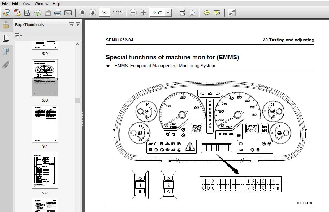
30. Testing and adjusting:
This section explains measuring instruments and measuring methods for testing and adjusting, and method of adjusting each part. The standard values and judgement criteria for testing and adjusting are explained in Testing and adjusting.
40. Troubleshooting:
This section explains how to find out failed parts and how to repair them. The troubleshooting is divided by failure modes. The “S mode” of the troubleshooting related to the engine may be also explained in the Chassis volume and Engine volume. In this case, see the Chassis volume.
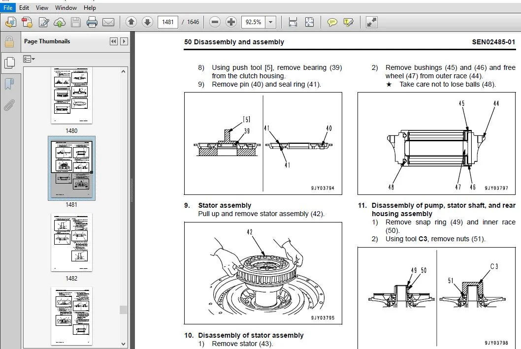
50. Disassembly and assembly:
This section explains the special tools and procedures for removing, installing, disassembling, and assembling each component, as well as precautions for them. In addition, tightening torque and quantity and weight of coating material, oil, grease, and coolant necessary for the work are also explained.
90. Diagrams and drawings (chassis volume)/Repair and replacement of parts (engine volume):
- Chassis volume
This section gives hydraulic circuit diagrams and electrical circuit diagrams. - Engine volume
This section explains the method of reproducing, repairing, and replacing parts.
TABLE OF CONTENTS:
Komatsu HD465-7E0 HD605-7E0 Dump Truck Shop Manual
COVER
................................................................................................................................................................   0
00 Index and foreword.................................................................................................................................................   0
	Index.............................................................................................................................................................   3
		Composition of shop manual....................................................................................................................................   4
		Table of contents.............................................................................................................................................   6
	Foreword and general information..................................................................................................................................  21
		Safety notice.................................................................................................................................................  22
		How to read the shop manual...................................................................................................................................  27
		Explanation of terms for maintenance standard.................................................................................................................  29
		Handling of electric equipment and hydraulic component........................................................................................................  31
		Handling of connectors newly used for engines.................................................................................................................  40
		How to read electric wire code................................................................................................................................  43
		Precautions when carrying out operation.......................................................................................................................  46
		Method of disassembling and connecting push-pull type coupler.................................................................................................  49
		Standard tightening torque table..............................................................................................................................  52
		Conversion table..............................................................................................................................................  56
01 Specification......................................................................................................................................................   0
	Specification and technical data..................................................................................................................................  63
		Specification drawing.........................................................................................................................................  64
		Specifications................................................................................................................................................  66
		Weight table..................................................................................................................................................  74
		Fuel, coolant and lubricants..................................................................................................................................  75
10 Structure, function and maintenance standard.......................................................................................................................   0
	Engine and cooling system.........................................................................................................................................  79
		Radiator, torque converter oil cooler, after cooler, work equipment oil cooler, fuel cooler...................................................................  80
		Fuel system...................................................................................................................................................  82
		Brake oil cooler..............................................................................................................................................  83
		Output shaft..................................................................................................................................................  84
	Power train, Part 1...............................................................................................................................................  87
		Power train skeleton..........................................................................................................................................  88
		Drive shaft...................................................................................................................................................  90
		Torque converter and transmission hydraulic piping............................................................................................................  92
		Brake cooling oil control valve (BCV).........................................................................................................................  94
		Torque converter..............................................................................................................................................  96
		Torque converter valve........................................................................................................................................ 103
		Transmission.................................................................................................................................................. 105
		Transmission control valve.................................................................................................................................... 121
		ECMV.......................................................................................................................................................... 122
	Power train, Part 2............................................................................................................................................... 131
		Axle.......................................................................................................................................................... 132
		Differential.................................................................................................................................................. 134
		Final drive................................................................................................................................................... 135
		Wheels........................................................................................................................................................ 136
	Steering system................................................................................................................................................... 139
		Steering column............................................................................................................................................... 140
		Steering linkage.............................................................................................................................................. 141
	Brake system...................................................................................................................................................... 145
		Brake piping.................................................................................................................................................. 146
		Brake valve................................................................................................................................................... 148
		Secondary brake valve......................................................................................................................................... 151
		Relay valve................................................................................................................................................... 152
		Front brake off valve......................................................................................................................................... 153
		Accumulator charge valve...................................................................................................................................... 154
		Accumulator................................................................................................................................................... 158
		Slack adjuster................................................................................................................................................ 159
		Brake......................................................................................................................................................... 161
		Parking brake solenoid valve.................................................................................................................................. 165
	Undercarriage and frame........................................................................................................................................... 167
		Suspension.................................................................................................................................................... 168
		Suspension cylinder........................................................................................................................................... 170
		Rear axle support............................................................................................................................................. 178
	Hydraulic system.................................................................................................................................................. 181
		Steering and hoist hydraulic piping........................................................................................................................... 182
		Dump body control............................................................................................................................................. 184
		Hydraulic tank................................................................................................................................................ 185
		Steering valve................................................................................................................................................ 186
		Crossover relief valve........................................................................................................................................ 190
		Steering cylinder............................................................................................................................................. 191
		Steering control valve........................................................................................................................................ 192
		Hoist valve................................................................................................................................................... 198
		Dump control valve (EPC valve)................................................................................................................................ 204
		Hoist cylinder................................................................................................................................................ 208
		Hydraulic pump................................................................................................................................................ 209
	Work equipment (Body)............................................................................................................................................. 215
		Auto greasing system.......................................................................................................................................... 216
	Cab and its attachments........................................................................................................................................... 239
		ROPS cab...................................................................................................................................................... 240
		Air conditioner............................................................................................................................................... 241
		Rear view monitor............................................................................................................................................. 247
	Electrical system, Part 1......................................................................................................................................... 251
		Machine monitor system........................................................................................................................................ 252
	Electrical system, Part 2......................................................................................................................................... 285
		Automatic shift control system................................................................................................................................ 286
		Transmission controller....................................................................................................................................... 290
		External power supply heater.................................................................................................................................. 304
		Automatic emergency steering system........................................................................................................................... 306
		Automatic suspension system................................................................................................................................... 310
		Retarder control system....................................................................................................................................... 313
		Battery disconnector switch................................................................................................................................... 324
		Dump control lever............................................................................................................................................ 330
	Electrical system, Part 3......................................................................................................................................... 335
		Payload meter II (Card type).................................................................................................................................. 336
	Electrical system, Part 4......................................................................................................................................... 367
		VHMS controller related....................................................................................................................................... 368
		ASR system (If equipped)...................................................................................................................................... 392
		Sensors, switches............................................................................................................................................. 398
20 Standard value table...............................................................................................................................................   0
	Standard service value table...................................................................................................................................... 419
		Standard value table for engine............................................................................................................................... 420
		Standard value table for machine.............................................................................................................................. 422
30 Testing and adjusting..............................................................................................................................................   0
	Testing and adjusting, Part 1..................................................................................................................................... 433
		Tools for testing, adjusting, and troubleshooting............................................................................................................. 435
		Sketch of special tool........................................................................................................................................ 441
		Testing engine speed.......................................................................................................................................... 442
		Testing air supply pressure (boost pressure).................................................................................................................. 443
		Testing exhaust temperature................................................................................................................................... 444
		Testing exhaust gas color..................................................................................................................................... 446
		Adjustment of valve clearance................................................................................................................................. 448
		Testing of compression pressure............................................................................................................................... 450
		Testing blow-by pressure...................................................................................................................................... 453
		Testing engine oil pressure................................................................................................................................... 454
		Testing EGR valve and bypass valve drive oil pressure......................................................................................................... 455
		Handling of fuel system devices............................................................................................................................... 457
		Releasing residual pressure from fuel system.................................................................................................................. 457
		Testing of fuel pressure...................................................................................................................................... 458
		Reduced cylinder mode operation............................................................................................................................... 459
		No-injection cranking......................................................................................................................................... 459
		Testing of fuel return rate and fuel leakage.................................................................................................................. 460
		Bleeding air from fuel circuit................................................................................................................................ 462
		Testing the fuel circuit for leakage.......................................................................................................................... 463
		Replacement and adjustment of fan belt........................................................................................................................ 464
		Replacement and adjustment of alternator and air conditioner compressor belt.................................................................................. 465
	Testing and adjusting, Part 2..................................................................................................................................... 467
		Testing torque converter stall speed.......................................................................................................................... 469
		Testing power train oil pressure.............................................................................................................................. 470
		Adjusting transmission speed sensor........................................................................................................................... 477
		Testing and adjusting brake oil pressure...................................................................................................................... 478
		Testing of accumulator nitrogen gas pressure and procedure for charging accumulator with nitrogen gas......................................................... 481
		Testing brake performance..................................................................................................................................... 487
		Bleeding air from brake circuit............................................................................................................................... 489
		Testing wear of front brake pad............................................................................................................................... 490
		Testing wear of rear brake disc............................................................................................................................... 491
		Method of releasing parking brake in an emergency............................................................................................................. 492
		Testing and adjusting front suspension cylinder............................................................................................................... 493
		Testing and adjusting rear suspension cylinder................................................................................................................ 497
		Testing and adjusting front suspension cylinder (Automatic suspension specification).......................................................................... 501
		Testing and adjusting hydraulic pressure in steering, hoist circuit........................................................................................... 502
		Testing and adjusting oil pressure in dump EPC circuit........................................................................................................ 505
		Air bleeding from steering cylinder........................................................................................................................... 506
		Procedure for raising dump body in emergency.................................................................................................................. 507
		Procedure for lowering dump body in emergency................................................................................................................. 508
		Adjusting body positioner sensor.............................................................................................................................. 510
		Handling of voltage circuit of engine controller.............................................................................................................. 511
		Adjusting transmission controller............................................................................................................................. 511
		Method for emergency escape at electrical system failure...................................................................................................... 512
	Testing and adjusting, Part 3..................................................................................................................................... 517
		Setting and adjusting of devices.............................................................................................................................. 518
		Special functions of machine monitor (EMMS)................................................................................................................... 530
	Testing and adjusting, Part 4..................................................................................................................................... 553
		Special functions of machine monitor (EMMS)................................................................................................................... 554
	Testing and adjusting, Part 5..................................................................................................................................... 595
		Request for opening ORBCOMM terminal.......................................................................................................................... 596
		VHMS controller initial setting procedure..................................................................................................................... 598
		Using method of KOMTRAX functions of ORBCOMM terminal......................................................................................................... 618
		Precautions for replacing VHMS controller..................................................................................................................... 621
		Pm Clinic check sheet......................................................................................................................................... 627
		Initial setting of payload meter.............................................................................................................................. 631
		Setting of payload meter built in VHMS........................................................................................................................ 632
		Setting of card-type payload meter (PLM-II) after installation or replacement................................................................................. 640
40 Troubleshooting....................................................................................................................................................   0
	General information on troubleshooting............................................................................................................................ 647
		Points to remember when troubleshooting....................................................................................................................... 648
		Sequence of events in troubleshooting......................................................................................................................... 649
		Check before troubleshooting.................................................................................................................................. 650
		Classification and procedures for troubleshooting............................................................................................................. 651
		Contents of troubleshooting table............................................................................................................................. 652
		Connection table for connector pin numbers.................................................................................................................... 654
		T-branch box and T-branch adapter table....................................................................................................................... 690
	Failure code table and fuse locations............................................................................................................................. 695
		Failure codes table........................................................................................................................................... 696
		Fuse locations................................................................................................................................................ 707
	Troubleshooting by failure code, Part 1........................................................................................................................... 713
		Failure code [1500L0] (Dual engagement)....................................................................................................................... 715
		Failure code [15B0NX] (Transmission oil filter: Clogging)..................................................................................................... 716
		Failure code [15F0KM] (R → F shifting abuse 1: Mistake in operation).......................................................................................... 718
		Failure code [15F0MB] (R → F shifting abuse 2: Mistake in operation).......................................................................................... 718
		Failure code [15F7KM] (Forward clutch disk abuse: Mistake in operation or setting)............................................................................ 719
		Failure code [15G0MW] (R clutch: Slipping).................................................................................................................... 720
		Failure code [15G7KM] (Reverse clutch disk abuse: Mistake in operation or setting)............................................................................ 722
		Failure code [15H0MW] (Hi clutch: Slipping)................................................................................................................... 724
		Failure code [15J0MW] ( Lo clutch: Slipping).................................................................................................................. 726
		Failure code [15K0MW] (1st clutch: Slipping).................................................................................................................. 728
		Failure code [15L0MW] (2nd clutch: Slipping).................................................................................................................. 730
		Failure code [15M0MW] (3rd clutch: Slipping).................................................................................................................. 732
		Failure code [15N0MW] (4th clutch: Slipping).................................................................................................................. 734
		Failure code [15SBL1] (R clutch solenoid: Fill signal is ON when command current is OFF)...................................................................... 736
		Failure code [15SBMA] (R clutch solenoid: Malfunction)........................................................................................................ 738
		Failure code [15SCL1] (Hi clutch solenoid: Fill signal is ON when command current is OFF)..................................................................... 739
		Failure code [15SCMA] (Hi clutch solenoid: Malfunction)....................................................................................................... 742
		Failure code [15SDL1] (Lo clutch solenoid: Fill signal is ON when command current is OFF)..................................................................... 743
		Failure code [15SDMA] (Lo clutch solenoid: Malfunction)....................................................................................................... 746
		Failure code [15SEL1] (1st clutch solenoid: Fill signal is ON when command current is OFF).................................................................... 747
		Failure code [15SEMA] (1st clutch solenoid: Malfunction)...................................................................................................... 750
	Troubleshooting by failure code, Part 2........................................................................................................................... 753
		Failure code [15SFL1] 2nd clutch solenoid: Fill signal is ON when command current is OFF...................................................................... 756
		Failure code [15SFMA] 2nd clutch solenoid: Malfunction........................................................................................................ 759
		Failure code [15SGL1] 3rd clutch solenoid: Fill signal is ON when command current is OFF...................................................................... 760
		Failure code [15SGMA] 3rd clutch solenoid: Malfunction........................................................................................................ 763
		Failure code [15SHL1] 4th clutch solenoid: Fill signal is ON when command current is OFF...................................................................... 764
		Failure code [15SHMA] 4th clutch solenoid: Malfunction........................................................................................................ 767
		Failure code [15SJMA] Lockup clutch solenoid: Malfunction..................................................................................................... 768
		Failure code [2C4MNX] Retarder cooling oil filter: Clogging................................................................................................... 770
		Failure code [2F00KM] Parking brake: Mistake in operation or setting.......................................................................................... 772
		Failure code [2G42ZG] Accumulator: Oil pressure reduction (Front)............................................................................................. 775
		Failure code [2G43ZG] Accumulator: Oil pressure reduction (Rear).............................................................................................. 775
		Failure code [6014NX] Hydraulic oil filter: Clogging.......................................................................................................... 776
		Failure code [989A00] Engine over run prevention command signal: Operating.................................................................................... 778
		Failure code [989D00] Rear section tipping over alarm: Alarm is activated..................................................................................... 778
		Failure code [A570NX] Engine oil filter: Clogging............................................................................................................. 779
		Failure code [AA10NX] Air cleaner element: Clogging........................................................................................................... 780
		Failure code [AB00MA] Alternator: Malfunction................................................................................................................. 782
		Failure code [B@BAZG] Abnormal lowering of engine oil pressure: Lowering of oil pressure...................................................................... 784
		Failure code [B@BAZK] Engine oil: Level too low............................................................................................................... 785
		Failure code [B@BCNS] Engine: Overheat........................................................................................................................ 786
		Failure code [B@BCZK] Lowering of radiator coolant: Lowering of level
........................................................................................ 788
		Failure code [B@BFZK] Lowering of fuel level.................................................................................................................. 790
		Failure code [B@C7NS] Brake cooling oil: Overheating (Rear)................................................................................................... 792
		Failure code [B@CENS] Overheating of torque converter oil..................................................................................................... 794
		Failure code [B@GAZK] Battery electrolyte level: Lowering of level............................................................................................ 795
		Failure code [B@JANS] Steering oil temperature: Overheat...................................................................................................... 796
	Troubleshooting by failure code, Part 3........................................................................................................................... 799
		Failure code [CA111] Abnormality in engine controller......................................................................................................... 802
		Failure code [CA115] Engine Ne or Bkup speed sensor error..................................................................................................... 804
		Failure code [CA122] Charge pressure sensor high error........................................................................................................ 806
		Failure code [CA123] Charge pressure sensor low error......................................................................................................... 808
		Failure code [CA131] Throttle sensor high error............................................................................................................... 810
		Failure code [CA132] Throttle sensor low error................................................................................................................ 813
		Failure code [CA135] Engine oil pressure sensor high error.................................................................................................... 814
		Failure code [CA141] Engine oil pressure sensor low error..................................................................................................... 816
		Failure code [CA144] Coolant temperature sensor high error.................................................................................................... 818
		Failure code [CA145] Coolant temperature sensor low error..................................................................................................... 820
		Failure code [CA153] Charge temperature sensor high error..................................................................................................... 822
		Failure code [CA154] Charge temperature sensor low error...................................................................................................... 824
		Failure code [CA187] Sensor power supply 2 low error.......................................................................................................... 824
		Failure code [CA212] Engine oil temperature sensor high error................................................................................................. 826
		Failure code [CA213] Engine oil temperature sensor low error.................................................................................................. 828
		Failure code [CA221] Atmospheric pressure sensor high error................................................................................................... 830
		Failure code [CA222] Atmospheric pressure sensor low error.................................................................................................... 832
		Failure code [CA227] Sensor power supply 2 high error......................................................................................................... 834
		Failure code [CA234] Engine overspeed......................................................................................................................... 836
		Failure code [CA238] Ne speed sensor power supply error....................................................................................................... 838
		Failure code [CA263] Fuel temperature sensor high error....................................................................................................... 840
		Failure code [CA265] Fuel temperature sensor low error........................................................................................................ 842
		Failure code [CA271] PCV1 short circuit....................................................................................................................... 844
		Failure code [CA272] PCV1 disconnection....................................................................................................................... 846
		Failure code [CA273] PCV2 short circuit....................................................................................................................... 848
		Failure code [CA274] PCV2 disconnection....................................................................................................................... 850
		Failure code [CA322] Injector #1 system disconnection or short circuit........................................................................................ 852
		Failure code [CA323] Injector #5 system disconnection or short circuit........................................................................................ 854
		Failure code [CA324] Injector #3 system disconnection or short circuit........................................................................................ 856
		Failure code [CA325] Injector #6 system disconnection or short circuit........................................................................................ 858
		Failure code [CA331] Injector #2 system disconnection or short circuit........................................................................................ 860
		Failure code [CA332] Injector #4 system disconnection or short circuit........................................................................................ 862
		Failure code [CA342] Engine controller data inconsistency..................................................................................................... 864
		Failure code [CA351] Injectors drive circuit error............................................................................................................ 864
		Failure code [CA352] Sensor power supply 1 low error.......................................................................................................... 865
		Failure code [CA386] Sensor power supply 1 high error......................................................................................................... 866
	Troubleshooting by failure code, Part 4........................................................................................................................... 869
		Failure code [CA431] Idle validation switch error............................................................................................................. 872
		Failure code [CA432] Idle validation action error............................................................................................................. 876
		Failure code [CA441] Battery voltage low error................................................................................................................ 876
		Failure code [CA442] Battery voltage high error............................................................................................................... 877
		Failure code [CA449] Common rail pressure high error 2........................................................................................................ 877
		Failure code [CA451] Common rail pressure sensor high error................................................................................................... 878
		Failure code [CA452] Common rail pressure sensor low error.................................................................................................... 880
		Failure code [CA553] Common rail pressure high error 1........................................................................................................ 881
		Failure code [CA554] Common rail pressure sensor: In-range error.............................................................................................. 882
		Failure code [CA559] Supply pump no-pressure feed error 1..................................................................................................... 883
		Failure code [CA689] Engine Ne speed sensor error............................................................................................................. 886
		Failure code [CA731] Engine Bkup speed sensor phase error..................................................................................................... 888
		Failure code [CA757] All engine controller data lost error.................................................................................................... 889
		Failure code [CA778] Engine Bkup speed sensor error........................................................................................................... 890
		Failure code [CA1228] EGR valve servo error 1................................................................................................................. 892
		Failure code [CA1625] EGR valve servo error 2................................................................................................................. 893
		Failure code [CA1626] Short circuit in bypass valve solenoid drive system..................................................................................... 894
		Failure code [CA1627] Disconnection in bypass valve solenoid drive system..................................................................................... 896
		Failure code [CA1628] Bypass valve servo error 1.............................................................................................................. 897
		Failure code [CA1629] Bypass valve servo error 2.............................................................................................................. 898
		Failure code [CA1631] Bypass valve lift sensor high error..................................................................................................... 900
		Failure code [CA1632] Bypass valve lift sensor low error...................................................................................................... 902
		Failure code [CA1633] KOMNET (datalink timeout) error......................................................................................................... 903
		Failure code [CA2185] Throttle sensor supply voltage high error............................................................................................... 904
		Failure code [CA2186] Throttle sensor power supply low error.................................................................................................. 906
		Failure code [CA2249] Supply pump no-pressure feed error 2.................................................................................................... 907
		Failure code [CA2271] EGR valve lift sensor high error........................................................................................................ 908
		Failure code [CA2272] EGR valve lift sensor low error......................................................................................................... 910
		Failure code [CA2351] Short circuit in EGR valve solenoid drive system........................................................................................ 912
		Failure code [CA2352] Disconnection in EGR valve solenoid drive system........................................................................................ 914
		Failure code [CA2555] Intake heater relay voltage low error................................................................................................... 915
		Failure code [CA2556] Intake heater relay voltage high error.................................................................................................. 916
	Troubleshooting by failure code, Part 5........................................................................................................................... 919
		Failure code [D19HKB] Stop lamp relay output system: Short circuit............................................................................................ 921
		Failure code [D5ZKKZ] Front brake cut-off solenoid valve: Disconnection, short circuit or short circuit to power supply line.................................. 922
		Failure code [DAF9KM] Wrong connection of connector........................................................................................................... 924
		Failure code [DAFRKR] Abnormal CAN communication (machine monitor): Abnormal communication.................................................................... 925
		Failure code [DAQ0KK] Transmission controller direct power supply: Lowering of power supply voltage........................................................... 926
		Failure code [DAQ0KT] Transmission controller nonvolatile memory: Abnormality in controller................................................................... 928
		Failure code [DAQ2KK] Transmission controller solenoid power supply: Power supply voltage too low............................................................. 930
		Failure code [DAQ9KQ] Transmission controller: Disagreement of model selection................................................................................ 932
		Failure code [DAQRKR] Abnormality in CAN communication (Transmission)......................................................................................... 933
		Failure code [DAQRMA] Transmission controller option setting: Malfunction..................................................................................... 938
		Failure code [DB10KT] Retarder controller nonvolatile memory: Abnormality in controller....................................................................... 938
		Failure code [DB12KK] Retarder controller solenoid power supply: Power supply system trouble.................................................................. 939
		Failure code [DB13KK] Retarder controller battery direct power supply: Power supply voltage too low........................................................... 941
		Failure code [DB19KQ] Disagreement of model selection (Retarder controller)................................................................................... 943
		Failure code [DB1RKR] CAN communication (retarder controller): Communication disabled......................................................................... 945
		Failure code [DB1RMA] Disagreement of option setting (Retarder controller).................................................................................... 949
		Failure code [DB2RKR] CAN communication (engine controller): Communication disabled........................................................................... 950
		Failure code [DBB0KK] or VHMS_LED display: "n9" → "01" VHMS controller: Low power supply voltage (input)...................................................... 956
		Failure code [DBB0KQ] or VHMS_LED display: "nF" → "11" VHMS controller: Disagreement of model selection signals............................................... 958
		Failure code [DBB3KK] or VHMS_LED display: "n9" → "05" VHMS controller battery power supply: Low power supply voltage (input)................................. 960
		Failure code [DBB5KP] or VHMS_LED display: "n9" → "04" VHMS controller 5 V power supply output: Low output voltage............................................ 962
		Failure code [DBB6KP] or VHMS_LED display: "n9" → "02" VHMS controller 24 V power supply output: Low output voltage........................................... 964
		Failure code [DBB7KP] or VHMS_LED display: "n9" → "03" VHMS controller 12 V power supply output: Low output voltage........................................... 966
		Failure code [DBBQKR] or VHMS_LED display: "n8" → "02" VHMS controller CAN communication: Defective communication (Abnormality in target component system).... 967
		Failure code [DBBRKR] Abnormality in CAN communication (VHMS)................................................................................................. 967
		Failure code [DBC2KK] ABS controller solenoid power supply: Power supply system trouble....................................................................... 968
		Failure code [DBC3KK] ABS controller battery direct power supply: Power supply voltage too low................................................................ 970
		Failure code [DBC9KQ] Disagreement of model selection (ABS controller)........................................................................................ 972
		Failure code [DBCRKR] Abnormality in CAN communication (ABS).................................................................................................. 973
		Failure code [DBCRMA] Disagreement of option setting (ABS controller)......................................................................................... 977
		Failure code [DDD7KX] Trouble in travel speed setting switch system: Out of input signal range................................................................ 978
		Failure code [DDD8KA] ARSC system switch system: Disconnection (If equipped).................................................................................. 980
		Failure code [DDD8KB] ARSC system switch system: Short circuit (If equipped).................................................................................. 982
		Failure code [DDD9KA] ABS system switch system: Disconnection................................................................................................. 984
		Failure code [DDD9KB] ABS system switch system: Short circuit................................................................................................. 986
		Failure code [DDDAKA] ASR system switch: Disconnection........................................................................................................ 988
		Failure code [DDDAKB] ASR system switch: Short circuit........................................................................................................ 990
		Failure code [DDP6L4] Service brake pressure switch trouble (Rear)............................................................................................ 992
		Failure code [DDTHKA] Hi clutch fill switch: Disconnection.................................................................................................... 994
		Failure code [DDTJKA] Lo clutch fill switch: Disconnection.................................................................................................... 996
		Failure code [DDTKKA] 1st clutch fill switch: Disconnection................................................................................................... 998
		Failure code [DDTLKA] 2nd clutch fill switch: Disconnection...................................................................................................1000
		Failure code [DDTMKA] (3rd clutch fill switch: Disconnection).................................................................................................1002
		Failure code [DDTNKA] R clutch fill switch: Disconnection.....................................................................................................1004
		Failure code [DDTPKA] 4th clutch fill switch: Disconnection...................................................................................................1006
		Failure code [DF10KA] Gear shift lever: Disconnection.........................................................................................................1008
		Failure code [DF10KB] Gear shift lever: Short circuit.........................................................................................................1011
		Failure code [DGE5KX] or VHMS_LED display: "n4" → "01" Atmospheric temperature sensor: Out of input signal range..............................................1016
		Failure code [DGF1KX] Transmission oil temperature sensor: Out of input signal range..........................................................................1018
		Failure code [DGR2KZ] Retarder oil temperature sensor system trouble: Ground fault (Rear wheel)...............................................................1020
		Failure code [DGR6KX] Steering oil temperature sensor: Input signal out of range..............................................................................1022
		Failure code [DGT1KX] Torque converter oil temperature sensor: Out of input signal range......................................................................1024
	Troubleshooting by failure code, Part 6...........................................................................................................................1027
		Failure code [DGT4KA] (or VHMS_LED display: “n3” → “12”) (Exhaust gas temperature sensor (F): Disconnection)..................................................1029
		Failure code [DGT4KB] (or VHMS_LED display: “n3” → “11”) (Exhaust gas temperature sensor (F): Short circuit)..................................................1032
		Failure code [DGT5KA] (or VHMS_LED display: “n3” → “22”) (Exhaust gas temperature sensor (R): Disconnection)..................................................1035
		Failure code [DGT5KB] (or VHMS_LED display: “n3” → “21”) (Exhaust gas temperature sensor (R): Short circuit)..................................................1038
		Failure code [DHE5KB] (or VHMS_LED display: “n3” → “32”) (Blow-by pressure sensor: Short circuit).............................................................1041
		Failure code [DHE5KY] (or VHMS_LED display: “n3” → “31”) (Blow-by pressure sensor: Short circuit with power supply line)......................................1044
		Failure code [DHP4KY] (or VHMS_LED display: “n5” → “44”) Short circuit in suspension pressure sensor system (Front right).....................................1046
		Failure code [DHP4KZ] (or VHMS_LED display: “n5” → “43”) Disconnection or ground fault in suspension pressure sensor system (Front right).....................1048
		Failure code [DHP5KY] (or VHMS_LED display: “n5” → “54”) Short circuit in suspension pressure sensor system (Front left)......................................1050
		Failure code [DHP5KZ] (or VHMS_LED display: “n5” → “53”) Disconnection or ground fault in suspension pressure sensor system (Front left)......................1052
		Failure code [DHP6KA] Trouble in suspension pressure sensor system (Right rear)...............................................................................1054
		Failure code [DHP6KX] Trouble in suspension pressure sensor system (Right rear)...............................................................................1055
		Failure code [DHP6KY] (or VHMS_LED display: “n5” → “64”) Short circuit in suspension pressure sensor system (Right rear)......................................1058
		Failure code [DHP6KZ] (or VHMS_LED display: “n5” → “63”) Disconnection or ground fault in suspension pressure sensor system (Right rear)......................1060
		Failure code [DHP7KA] Suspension pressure sensor system: Disconnection (Left rear)............................................................................1062
		Failure code [DHP7KX] Failure in suspension pressure sensor system trouble: Out of input signal range (Left rear).............................................1064
		Failure code [DHP7KY] or VHMS_LED display: "n5" → "74" Suspension pressure sensor system: Short circuit (Left rear)...........................................1066
		Failure code [DHP7KZ] or VHMS_LED display: "n5" → "73" Suspension pressure sensor system: Disconnection or ground fault (Left rear)...........................1068
		Failure code [DHT5KX] Torque converter oil pressure sensor: Out of input signal range.........................................................................1070
		Failure code [DHT5L6] Torque converter oil pressure sensor: Disagreement of run and stop condition with signal................................................1072
		Failure code [DHU2KX] Front accumulator oil pressure sensor: Out of input signal range........................................................................1074
		Failure code [DHU3KX] Rear accumulator oil pressure sensor: Out of input signal range.........................................................................1076
		Failure code [DHU6KX] Trouble in ABS control valve pressure sensor (Front right)..............................................................................1078
		Failure code [DHU7KX] Trouble in ABS control valve pressure sensor (Front left)...............................................................................1080
		Failure code [DHU8KX] Trouble in ABS control valve pressure sensor (Front right)..............................................................................1082
		Failure code [DHU9KX] Trouble in ABS control valve pressure sensor (Front right)..............................................................................1084
		Failure code [DJF1KA] Fuel level sensor: Disconnection........................................................................................................1086
		Failure code [DK30KX] Steering angle potentiometer: Trouble (Disconnection)...................................................................................1088
		Failure code [DK51L5] Retarder lever potentiometer: Potentiometer signal is inconsistent with swich signal....................................................1089
		Failure code [DK52KX] Failure in hoist lever potentiometer 1: Out of input signal range.......................................................................1092
		Failure code [DK53L8] Failure in hoist lever potentiometer 2: Disagreement of analog signal...................................................................1094
		Failure code [DK54KX] Body positioner sensor: Out of input signal range.......................................................................................1096
		Failure code [DKD0L6] Failure in steering speed sensor........................................................................................................1098
		Failure code [DKH0KX] Clinometer sensor signal out of range...................................................................................................1100
		Failure code [DKH1KX] or VHMS_LED display: "n4"→"33" Abnormality in clinometer sensor.........................................................................1102
		Failure code [DLF1KA] Transmission input shaft speed sensor: Disconnection....................................................................................1104
		Failure code [DLF1LC] Transmission input shaft speed sensor: Disagreement of revolution speed signal..........................................................1106
		Failure code [DLF2KA] Transmission intermediate shaft speed sensor: Disconnection.............................................................................1108
		Failure code [DLF2LC] Transmission intermediate shaft speed sensor: Disagreement of revolution speed signal...................................................1110
	Troubleshooting by failure code, Part 7...........................................................................................................................1113
		Failure code [DLF6KA] Disconnection in wheel speed sensor (Front right).......................................................................................1115
		Failure code [DLF6L3] Trouble in wheel speed sensor (Front right).............................................................................................1116
		Failure code [DLF7KA] Disconnection in wheel speed sensor (Front left)........................................................................................1117
		Failure code [DLF7L3] Trouble in wheel speed sensor (Front left)..............................................................................................1118
		Failure code [DLF8KA] Disconnection in wheel speed sensor (Right rear)........................................................................................1120
		Failure code [DLF8L3] Trouble in wheel speed sensor (Right rear)..............................................................................................1122
		Failure code [DLF8LC] Trouble in wheel speed sensor system (Right rear).......................................................................................1124
		Failure code [DLF8MA] Disconnection in wheel speed sensor (Right rear)........................................................................................1125
		Failure code [DLF9KA] Disconnection in wheel speed sensor (Left rear).........................................................................................1126
		Failure code [DLF9L3] Trouble in wheel speed sensor (Left rear)...............................................................................................1128
		Failure code [DLF9LC] Trouble in wheel speed sensor system (Left rear)........................................................................................1130
		Failure code [DLF9MA] Disconnection in wheel speed sensor (Left rear).........................................................................................1131
		Failure code [DLT3KA] Disconnection in transmission output shaft speed sensor system..........................................................................1132
		Failure code [DLT3LC] Trouble in transmission output shaft speed sensor.......................................................................................1134
		Failure code [DLT4KA] Disconnection in transmission output shaft speed sensor.................................................................................1136
		Failure code [DLT4MA] Disconnection in transmission output shaft speed sensor.................................................................................1138
		Failure code [DV00KB] Short circuit in buzzer output..........................................................................................................1140
		Failure code [DW2AKA] Disconnection in main pressure variable valve output....................................................................................1142
		Failure code [DW2AKB] Ground fault in main pressure variable valve output circuit.............................................................................1144
		Failure code [DW2AKY] Hot short in main pressure variable valve output circuit................................................................................1146
		Failure code [DW2AL1] Defective reset of main pressure variable valve.........................................................................................1148
		Failure code [DW2ALH] Malfunction of main pressure variable valve.............................................................................................1150
		Failure code [DW35KZ] Trouble in output system of auto suspension solenoid 1 (Disconnection or short circuit).................................................1152
		Failure code [DW36KZ] Trouble in output system of auto suspension solenoid 2 (Disconnection or short circuit).................................................1154
		Failure code [DW72KZ] Trouble in kick-out solenoid output system (Disconnection or short circuit).............................................................1156
		Failure code [DW73KZ] Trouble in hoist select valve output system (Disconnection or short circuit)............................................................1158
		Failure code [DW78KZ] Trouble in brake cooling valve (BCV) (rear wheel) output system (Disconnection or short circuit)........................................1160
		Failure code [DWNBK4] Trouble in ASR shut-off valve (Valve keeps operating)...................................................................................1162
		Failure code [DWNBKA] Disconnection in ASR shut-off valve output circuit......................................................................................1164
		Failure code [DWNBKB] Ground fault in ASR shut-off valve output circuit.......................................................................................1166
		Failure code [DWNBKY] Short circuit in ASR shut-off valve output circuit......................................................................................1168
		Failure code [DWNBMA] Trouble in ASR shut-off valve (Valve does not operate)..................................................................................1169
		Failure code [DWNDKZ] Trouble in ABS cut-off valve (Front) system.............................................................................................1170
		Failure code [DWNDMA] Defective ABS cut-off valve (Front).....................................................................................................1172
		Failure code [DWNEKZ] Trouble in ABS cut-off valve (Rear) system..............................................................................................1174
		Failure code [DWNEMA] Defective ABS cut-off valve (Rear)......................................................................................................1176
	Troubleshooting by failure code, Part 8...........................................................................................................................1179
		Failure code [DX11K4] Trouble in rear brake proportional pressure reducing solenoid valve (Valve keeps operating).............................................1182
		Failure code [DX11KA] Disconnection in rear brake proportional pressure reducing solenoid valve output circuit................................................1184
		Failure code [DX11KB] Short circuit in rear brake proportional pressure reducing solenoid valve...............................................................1185
		Failure code [DX11KY] Short circuit in rear wheel proportional pressure reducing solenoid valve output circuit................................................1186
		Failure code [DX11MA] Trouble in rear wheel proportional pressure reducing solenoid valve (Valve does not operate)............................................1187
		Failure code [DX13KA] Disconnection in hoist EPC valve output circuit.........................................................................................1188
		Failure code [DX13KB] Short circuit in hoist EPC valve output circuit.........................................................................................1190
		Failure code [DX13KY] Short circuit in hoist EPC valve output circuit.........................................................................................1192
		Failure code [DX17K4] Trouble in ASR proportional pressure reducing solenoid valve (right) (Valve keeps operating)............................................1194
		Failure code [DX17KA] Disconnection in ASR proportional pressure reducing solenoid valve (right) output circuit...............................................1196
		Failure code [DX17KB] Ground fault in ASR proportional pressure reducing solenoid valve (right) output circuit................................................1198
		Failure code [DX17KY] Short circuit in ASR proportional pressure reducing solenoid valve (right) output circuit...............................................1200
		Failure code [DX17MA] Trouble in ASR proportional pressure reducing solenoid valve (right) (Valve does not operate)...........................................1200
		Failure code [DX18K4] Trouble in ASR proportional pressure reducing solenoid valve (left) (Valve keeps operating).............................................1202
		Failure code [DX18KA] Disconnection in ASR proportional pressure reducing solenoid valve (left) output circuit................................................1204
		Failure code [DX18KB] Ground fault in ASR proportional pressure reducing solenoid valve (left) output circuit.................................................1206
		Failure code [DX18KY] Short circuit in ASR proportional pressure reducing solenoid valve (left) output circuit................................................1208
		Failure code [DX18MA] Trouble in ASR proportional pressure reducing solenoid valve (left) (Valve does not operate)............................................1208
		Failure code [DX21KA] Disconnection in ABS control valve output circuit (Front right).........................................................................1209
		Failure code [DX21KB] Ground fault in ABS control valve output circuit (Front right)..........................................................................1210
		Failure code [DX21KY] Hot short in ABS control valve output circuit (Front right).............................................................................1211
		Failure code [DX21MA] Defective ABS control valve (Front right)...............................................................................................1212
		Failure code [DX22KA] Disconnection in ABS control valve output circuit (Front left)..........................................................................1213
		Failure code [DX22KB] Ground fault in ABS control valve output circuit (Front left)...........................................................................1214
		Failure code [DX22KY] Hot short in ABS control valve output circuit (Front left)..............................................................................1215
		Failure code [DX22MA] Defective ABS control valve (Front left)................................................................................................1216
		Failure code [DX23KA] Disconnection in ABS control valve output circuit (Rear right)..........................................................................1217
		Failure code [DX23KB] Ground fault in ABS control valve output circuit (Rear right)...........................................................................1218
		Failure code [DX23KY] Hot short in ABS control valve output circuit (Rear right)..............................................................................1219
		Failure code [DX23MA] Defective ABS control valve (Rear right)................................................................................................1220
		Failure code [DX24KA] Disconnection in ABS control valve output circuit (Rear left)...........................................................................1221
		Failure code [DX24KB] Ground fault in ABS control valve output circuit (Rear left)............................................................................1222
		Failure code [DX24KY] Hot short in ABS control valve output circuit (Rear left)...............................................................................1223
		Failure code [DX24MA] Defective ABS control valve (Rear left).................................................................................................1224
		Failure code [DX25MA] Defective ABS front wheel system control valve..........................................................................................1225
		Failure code [DX26MA] Defective ABS rear wheel system control valve...........................................................................................1225
	Troubleshooting by failure code, Part 9...........................................................................................................................1227
		Failure code [DXH1KA] Lockup clutch solenoid output circuit: Disconnection....................................................................................1230
		Failure code [DXH1KB] Lockup clutch solenoid output circuit: Short circuit....................................................................................1232
		Failure code [DXH1KY] Lockup clutch solenoid output circuit: Short circuitto power supply line................................................................1234
		Failure code [DXH2KA] Hi clutch solenoid output circuit: Disconnection........................................................................................1236
		Failure code [DXH2KB] Hi clutch solenoid output circuit: Short circuit........................................................................................1238
		Failure code [DXH2KY] Hi clutch solenoid output circuit: Short circuit top ower supply line...................................................................1240
		Failure code [DXH3KA] Lo clutch solenoid output circuit: Disconnection........................................................................................1244
		Failure code [DXH3KB] Lo clutch solenoid output circuit: Short circuit........................................................................................1246
		Failure code [DXH3KY] Lo clutch solenoid output circuit: Short circuit in power supply line...................................................................1248
		Failure code [DXH4KA] 1st clutch solenoid output circuit: Disconnection.......................................................................................1252
		Failure code [DXH4KB] 1st clutch solenoid output circuit: Short circuit.......................................................................................1254
		Failure code [DXH4KY] 1st clutch solenoid output circuit: Short circuit to power supply line..................................................................1256
		Failure code [DXH5KA] 2nd clutch solenoid output circuit: Disconnection.......................................................................................1260
		Failure code [DXH5KB] 2nd clutch solenoid output circuit: Short circuit.......................................................................................1262
		Failure code [DXH5KY] 2nd clutch solenoid output circuit: Short circuit in power supply line..................................................................1264
		Failure code [DXH6KA] 3rd clutch solenoid output circuit: Disconnection.......................................................................................1268
		Failure code [DXH6KB] 3rd clutch solenoid output circuit: Short circuit.......................................................................................1270
		Failure code [DXH6KY] 3rd clutch solenoid output circuit: Short circuit to power supply line..................................................................1272
		Failure code [DXH7KA] R clutch solenoid output circuit: Disconnection.........................................................................................1276
		Failure code [DXH7KB] R clutch solenoid output circuit: Short circuit.........................................................................................1278
		Failure code [DXH7KY] R clutch solenoid output circuit: Short circuit to power supply line....................................................................1280
		Failure code [DXHHKA] 4th clutch solenoid output circuit: Disconnection.......................................................................................1282
		Failure code [DXHHKB] 4th clutch solenoid output circuit: Short circuit.......................................................................................1284
		Failure code [DXHHKY] 4th clutch solenoid output circuit: Short circuit to power supply line..................................................................1286
		Failure code [F@BBZL] or VHMS_LED display: "n3"→"38" Blow-by pressure: High error.............................................................................1289
		Failure code [F@BYNR] or VHMS_LED display: "n3"→"62" Exhaust gas temperature (F): Abnormal heat...............................................................1290
		Failure code [F@BYNS] or VHMS_LED display: "n3"→"61" Exhaust gas temperature (F): Overheat....................................................................1292
		Failure code [F@BZNR] or VHMS_LED display: "n3"→"72" Exhaust gas temperature (R): Abnormal heat...............................................................1294
		Failure code [F@BZNS] or VHMS_LED display: "n3"→"71" Exhaust gas temperature (R): Overheat....................................................................1296
	Troubleshooting of electrical system (E-mode).....................................................................................................................1299
		Before troubleshooting of electric system.....................................................................................................................1301
		Contents of troubleshooting table.............................................................................................................................1302
		E-1 Engine does not start.....................................................................................................................................1303
		E-2 Automatic preheating does not operate.....................................................................................................................1306
		E-3 Machine monitor does not display all, when starting switch is turned ON...................................................................................1310
		E-4 Machine monitor does not operate when starting switch is OFF..............................................................................................1312
		E-5 Alarm buzzer does not sound...............................................................................................................................1314
		E-6 Alarm buzzer does not stop sounding.......................................................................................................................1316
		E-7 Gauges of machine monitor, caution lamps or character display section do not display properly.............................................................1318
		E-8 A selection of the display in character display section cannot be changed.................................................................................1319
		E-9 Power mode selecting function does not operate properly...................................................................................................1322
		E-10 AISS function does not operate properly..................................................................................................................1323
		E-11 Seat belt caution lamp does not display properly.........................................................................................................1324
		E-12 Turn signal lamp or turning lamp (hazard lamp) do not work properly......................................................................................1325
		E-13 Night illumination (lighting) does not work properly.....................................................................................................1328
		E-14 Emergency steering does not operate......................................................................................................................1340
		E-15 Hoist lever does not operate normally....................................................................................................................1346
		E-16 Electric priming pump does not operate or does not stop automatically....................................................................................1348
	Troubleshooting of hydraulic and mechanical system (H-mode).......................................................................................................1351
		Contents of troubleshooting table.............................................................................................................................1353
		H-1 Machine does not start....................................................................................................................................1354
		H-2 Machine does not travel smoothly (hunting)................................................................................................................1356
		H-3 Lockup cannot be cancelled................................................................................................................................1356
		H-4 Excessive shock when starting or shifting excessive.......................................................................................................1357
		H-5 Transmission does not shift up............................................................................................................................1358
		H-6 Machine lacks power or speed when traveling...............................................................................................................1360
		H-7 Time lag is excessive when starting or shifting gear......................................................................................................1364
		H-8 Torque converter oil temperature is high..................................................................................................................1366
		H-9 Torque converter oil pressure is low......................................................................................................................1367
		H-10 Front brake is ineffective...............................................................................................................................1368
		H-11 Rear brake is ineffective................................................................................................................................1369
		H-12 Steering wheel is heavy..................................................................................................................................1370
		H-13 Steering wheel does not work.............................................................................................................................1371
		H-14 Steering wheel vibrates..................................................................................................................................1372
		H-15 Dump body lifting speed is slow..........................................................................................................................1373
		H-16 Dump body does not work..................................................................................................................................1374
		H-17 Excessive hydraulic drift of dump body...................................................................................................................1375
	Troubleshooting of engine (S-mode)................................................................................................................................1377
		Method of using troubleshooting chart.........................................................................................................................1380
		S-1 Starting performance of engine is poor....................................................................................................................1384
		S-2 Engine does not start.....................................................................................................................................1386
		S-3 Engine does not pick up smoothly..........................................................................................................................1390
		S-4 Engine stops during operation.............................................................................................................................1391
		S-5 Engine does not rotate smoothly...........................................................................................................................1392
		S-6 Engine lack output (or lacks power).......................................................................................................................1393
		S-7 Exhaust gas is black (incomplete combustion)..............................................................................................................1394
		S-8 Oil consumption is excessive (or exhaust gas is blue).....................................................................................................1396
		S-9 Oil becomes dirty quickly.................................................................................................................................1397
		S-10 Fuel consumption is excessive............................................................................................................................1398
		S-11 Oil is in coolant (or coolant spurts back or coolant level goes down)....................................................................................1399
		S-12 Oil pressure drops.......................................................................................................................................1400
		S-13 Oil level rises (Entry of coolant or fuel)...............................................................................................................1402
		S-14 Coolant temperature becomes too high (Overheating).......................................................................................................1404
		S-15 Abnormal noise is made...................................................................................................................................1405
		S-16 Vibration is excessive...................................................................................................................................1406
		S-17 Air cannot be bled from fuel circuit.....................................................................................................................1408
50 Disassembly and assembly...........................................................................................................................................   0
	General information on disassembly and assembly...................................................................................................................1411
		How to read this manual.......................................................................................................................................1412
		Coating materials list........................................................................................................................................1414
		Special tool list.............................................................................................................................................1417
		Sketches of special tools.....................................................................................................................................1420
	Engine and cooling system.........................................................................................................................................1425
		Removal and installation of fuel supply pump assembly.........................................................................................................1426
		Removal and installation of fuel injector assembly............................................................................................................1429
		Removal and installation of cylinder head assembly............................................................................................................1433
		Removal and installation of engine front seal.................................................................................................................1445
		Removal and installation of engine rear seal..................................................................................................................1448
		Removal and installation of engine assembly...................................................................................................................1452
		Removal and installation of radiator assembly.................................................................................................................1459
		Removal and installation of output shaft assembly.............................................................................................................1463
		Disassembly and assembly of output shaft assembly.............................................................................................................1464
		Removal and installation of brake and power train oil cooler assembly.........................................................................................1467
	Power train, Part 1...............................................................................................................................................1471
		Removal and installation of torque converter and transmission assembly........................................................................................1472
		Separation and coupling of transmission assembly and torque converter assembly................................................................................1475
		Disassembly and assembly of transmission assembly and torque converter assembly...............................................................................1476
		Disassembly and assembly of torque converter assembly.........................................................................................................1478
		Disassembly and assembly of transmission assembly.............................................................................................................1488
		Removal and installation of transmission control valve assembly (ECMV assembly)...............................................................................1519
		Disassembly and assembly of transmission control valve assembly (ECMV assembly)...............................................................................1520
	Power train, Part 2...............................................................................................................................................1525
		Removal and installation of differential assembly.............................................................................................................1526
		Disassembly and assembly of differential assembly.............................................................................................................1528
		Removal and installation of final drive carrier assembly......................................................................................................1540
		Disassembly and assembly of final drive carrier assembly......................................................................................................1541
		Disassembly and assembly of front wheel hub assembly..........................................................................................................1542
	Steering system...................................................................................................................................................1547
		Disassembly and assembly of steering cylinder assembly........................................................................................................1548
	Brake system......................................................................................................................................................1553
		Removal and installation of front brake caliper pads..........................................................................................................1554
		Removal and installation of front brake calipers assembly.....................................................................................................1555
		Disassembly and assembly of front brake calipers assembly.....................................................................................................1556
		Removal and installation of final drive and rear brake assembly...............................................................................................1558
		Removal and installation of final drive, rear brake, and parking brake assembly...............................................................................1561
		Disassembly and assembly of final drive, rear brake, and parking brake assembly...............................................................................1562
	Undercarriage and frame...........................................................................................................................................1575
		Removal and installation of front wheel assembly..............................................................................................................1576
		Removal and installation of rear wheel assembly...............................................................................................................1578
		Removal and installation of front suspension cylinder assembly................................................................................................1580
		Disassembly and assembly of front suspension cylinder assembly (Cylinder with buffer ring)....................................................................1582
		Removal and installation of rear suspension cylinder assembly.................................................................................................1585
		Disassembly and assembly of rear suspension cylinder assembly (Cylinder with buffer ring).....................................................................1586
	Hydraulic system..................................................................................................................................................1591
		Disassembly and assembly of hoist cylinder assembly...........................................................................................................1592
	Body..............................................................................................................................................................1597
		Removal and installation of body assembly.....................................................................................................................1598
	Cab and its attachments...........................................................................................................................................1603
		Disassembly and assembly of operator's seat assembly..........................................................................................................1604
		Removal and installation of air conditioner unit assembly.....................................................................................................1613
	Electrical system.................................................................................................................................................1617
		Removal and installation of engine controller assembly........................................................................................................1618
		Removal and installation of transmission controller assembly..................................................................................................1619
		Removal and installation of retarder controller assembly......................................................................................................1620
90 Diagrams and drawings..............................................................................................................................................   0
	Hydraulic diagrams and drawings...................................................................................................................................1623
		Power train hydraulic circuit diagram.........................................................................................................................1624
		Steering and hoist hydraulic circuit diagram..................................................................................................................1625
		Brake hydraulic circuit diagram...............................................................................................................................1627
	Electrical diagrams and drawings..................................................................................................................................1631
		Electrical circuit diagram inside cab (1/3)...................................................................................................................1633
		Electrical circuit diagram inside cab (2/3)...................................................................................................................1634
		Electrical circuit diagram inside cab (3/3)...................................................................................................................1635
		Electrical circuit diagram outside cab (1/3)..................................................................................................................1636
		Electrical circuit diagram outside cab (2/3)..................................................................................................................1637
		Electrical circuit diagram outside cab (3/3)..................................................................................................................1638
		Electrical circuit diagram for VHMS...........................................................................................................................1639
		Electrical circuit diagram for ASR (If equipped)..............................................................................................................1640
		Air conditioner electrical circuit diagram....................................................................................................................1641
		Electrical circuit diagram for auto greasing (If equipped)....................................................................................................1642
		Electrical circuit diagram of external power supply heater....................................................................................................1643
		Connectors table and arrangement drawing
.....................................................................................................................1644
KOMATSU HD465-7E0 HD605-7E0 DUMP TRUCK SHOP MANUAL SEN01081-18 – PDF DOWNLOAD:
IMAGES PREVIEW OF THE MANUAL:
PLEASE NOTE:
- This is the SAME MANUAL used by the dealerships to diagnose your vehicle
- No waiting for couriers / posts as this is a PDF manual and you can download it within 2 minutes time once you make the payment.
- Your payment is all safe and the delivery of the manual is INSTANT – You will be taken to the DOWNLOAD PAGE.
- So have no hesitations whatsoever and write to us about any queries you may have : heydownloadss @gmail.com


