
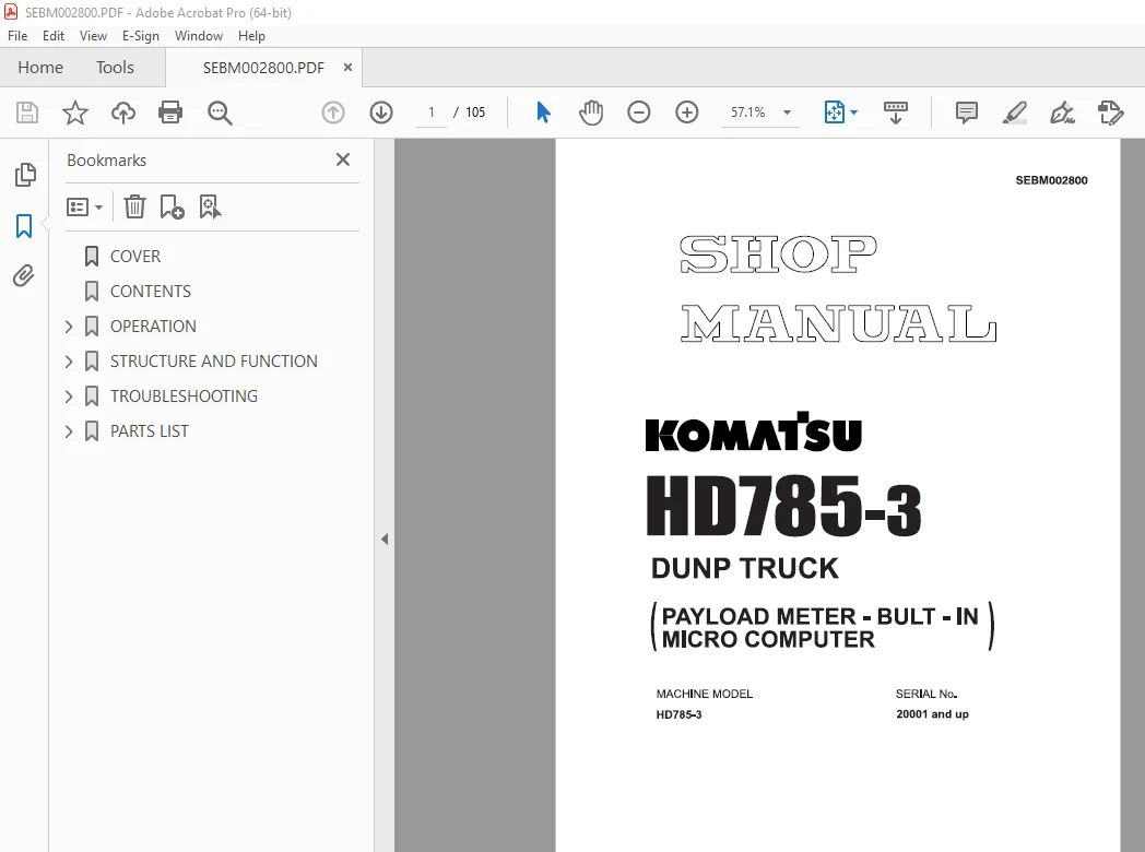
Komatsu HD785-3 Dump Truck Shop Manual SEBM002800 PDF
$26.95
Komatsu HD785-3 Dump Truck Shop Manual SEBM002800 – PDF DOWNLOAD
MACHINE MODEL SERIAL No.
HD785-3 20001 and up
Description
Komatsu HD785-3 Dump Truck Shop Manual SEBM002800 – PDF DOWNLOAD
FILE DETAILS:
Komatsu HD785-3 Dump Truck Shop Manual SEBM002800 – PDF DOWNLOAD
Language : English
Pages : 105
Downloadable : Yes
File Type : PDF
IMAGES PREVIEW OF THE MANUAL:
DESCRIPTION:
Komatsu HD785-3 Dump Truck Shop Manual SEBM002800 – PDF DOWNLOAD
MACHINE MODEL SERIAL No.
HD785-3 20001 and up
1. INTRODUCTION:
• The signals from the pressure sensors, clinometer (not installed on -6О0С specification machine),
body float detection, and neutral detection are input to the payload meter. These
signals are processed Ьу the built-in micro computer, the payload is calculated and displayed
on the panel. At the same time, the external display lamps show the loading
condition.
• The payload meter always carries out self diagnosis of this system, and if any abnormality
or warning is generated, it displays the details.
• Using the control switches on the payload meter, it is possiЫe to display various data, such
as the total payload from а certain time, the overall number of cycles, or the abnormalities
and warnings that are now being generated or have occurred and have already been
corrected.
• The payload meter automatically stores in memory various operating data for the dump
truck such as the payload, time, distance, travel speed for each cycle, the date and time
that the engine was started and stopped, the date and time of abnormalities or warnings
that occurred or were canceled, and the total payload and the overall number of cycles
from а certain time.
• These automatically recorded data are retained even when the power is switched off, so if
а personal computer is connected to the payload meter through the connection port for the
communications саЫе inside the саЬ, it is possiЫe to send (download) the data later to а
personal computer using саЫе communication (ANSI/EIA RS-232C).
ln addition, based оп these data, it is possiЫe to display the operation data on the screen
of the computer, to print out the data, or to convert the data for use with Lotus 1-2-3.
• lt is also possiЫe to set а memory card in the payload meter and to write the various data
to the memory card. This memory card сап then Ье used to load the data into а personal
computer and to сапу out the same data processing that is availaЫe using саЫе communications.
* То download the data, read the data from the memory card to the personal computer, and
сапу out the data processing, it is necessary to use the personal computer software provided
Ьу Komatsu.
• lt is possiЫe to set the machine ID, open ID, and speed limit for each payload meter (that
is, each machine).
TABLE OF CONTENTS:
Komatsu HD785-3 Dump Truck Shop Manual SEBM002800 – PDF DOWNLOAD
MACHINE MODEL SERIAL No.
HD785-3 20001 and up
COVER 1
CONTENTS 2
OPERATION 3
1 INTRODUCTION 4
2 GENERAL LOCATIONS 5
3 CONTENT OF DISPLAY (CONTROLLER,EXTERNAL DISPLAY LAMPS) 8
4 EXTERNAL DISPLAY LAMPS 12
5 DETAILS OF DATA STORED IN MEMORY OF PAYLOAD METER 14
6 OPERATION OF SWITCHES 19
6 1 CARRYING OUT CALIBRATION 20
6 2 FORCED DISPLAY OF TOTAL PAYLOAD AND OVERALL NUMBER OF CYCLES FORCED DISPLAY OF ABNORMALITIES,WARNINGS WHEN THEY HAVE OCCURRED 21
6 3 OPERATOR CHECK MODE 25
6 4 DIMMING LIGHTS ON MONITOR DISPLAY 39
6 5 ADJUSTING BUZZER SOUND LEVEL 39
7 ABNORMALITY AND WARNING DISPLAY (ERROR CODE) 40
8 WHEN F-09 IS DISPLAYED FOR THE ERROR CODE (PROCEDURE FOR REPLACING BATTERY) 48
9 OPERATION IF F-CAL IS DISPLAYED AS AN ERROR CODE OR THE CONTROLLER IS REPLACED 51
STRUCTURE AND FUNCTION 52
STRUCTURE OF SYSTEM 53
ELECTRICAL WIRING DIAGRAM 54
PRINCIPLE OF CALCULATION 55
FEATURES OF EQUIPMENT 57
TROUBLESHOOTING 69
PRECAUTIONS WHEN CARRYING OUT MAINTENANCE 70
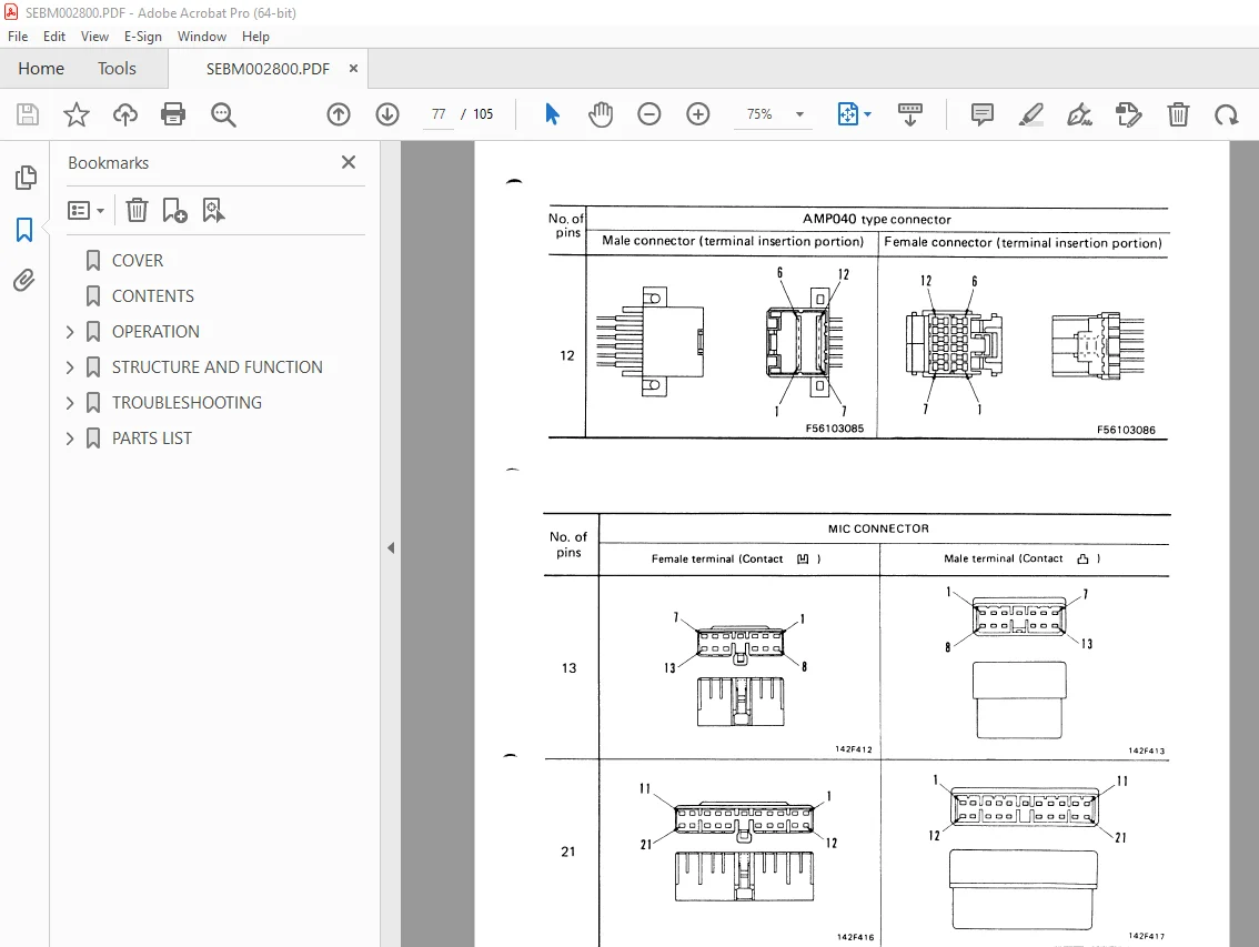
CONNECTION TABLE FOR CONNECTOR PINS 75
TROUBLESHOOTING FOR PAYLOAD METER SYSTEM 81
L-1 DISPLAY DOES NOT APPEAR WHEN STARTING SWITCH IS TURNED ON 82
L-2 NO EXTERNAL DISPLAY LAMPS LIGHT UP AFTER STARTING SWITCH IS TURNED ON 83
L-3 LIGHTING UP OF EXTERNAL DISPLAY LAMPS DOES NOT MATCH CONDITIONS FOR LIGHTING UP 84
L-4 LIGHTING UP LEVEL OF EXTERNAL DISPLAY LAMPS IS NOT CORRECT 85
L-5 CYCLE DATA IS NOT RECORDED,ENGINE DATA IS NOT RECORDED 86
L-6 CALIBRATION CANNOT BE CARRIED OUT,TIME DISPLAY IS GIVEN WITHOUT FULFILLING CONDITIONS 87
L-7 ABNORMALITY IN DISPLAY LOGIC 88
a) AFTER LOADING,0 DISPLAY REMAINS EVEN WHEN STARTING TO DRIVE LOADED MACHINE 88
b) AFTER STARTING TO DRIVE LOADED MACHINE,VALUE ON TRAVEL DISTANCE DISPLAY DOES NOT INCREASE 88
c) TRAVEL SPEED IS ABOVE SPEED LIMIT BUT SP:SP DISPLAY IS NOT GIVEN 88
d) TOTAL PAYLOAD DISPLAY IS NOT GIVEN 88
L-8 B-FL DISPLAY REMAINS AND DOES NOT CHANGE 89
L-9 F-09 IS DISPLAYED:DROP IN VOLTAGE OF BACKUP BATTERY BUILT INTO PAYLOAD METER 90
L-10 [ ] FULL DISPLAY IS GIVEN 90
・ L FUL:CYCLE OPERATED 90
・ E FUL:ENGINE ON/OFF COUNT 90
・ F FUL:ABNORMALITY,WARNING 90
・ H FUL:TOTAL PAYLOAD,OVERALL NUMBER OF CYCLES 90
L-11 F-20 IS DISPLAYED 91
L-12 F-21-24 IS DISPLAYED:DISCONNECTION,SHORT CIRCUIT WITH GROUND IN SUSPENSION PRESSURE SENSOR SYSTEM 92
L-13 F-25-28 IS DISPLAYED:SHORT CIRCUIT IN POWER SOURCE FOR SUSPENSION PRESSURE SENSOR SYSTEM 94
L-14 F-CAL IS DISPLAYED:CALIBRATION NOT CARRIED OUT,DATA INSIDE PAYLOAD METER DAMAGED 95
L-15 F-41-45 IS DISPLAYED:SHORT CIRCUIT IN POWER SOURCE FOR EXTERNAL DISPLAY LAMP RELAY 96
L-16 L-BAD IS DISPLAYED:CYCLE DATA RECORDED WHEN MACHINE WAS ROCKING 97
L-17 MACHINE IS NOT BEING LOADED,BUT EXTERNAL DISPLAY LAMP GIVES ESTIMATE DISPLAY AFTER LOADING,DISPLAY CHANGES TO TIME DISPLAY BEFORE MACHINE TRAVELS 160 M 98
L-18 F-31 IS DISPLAYED:SHORT CIRCUIT,DISCONNECTION IN CLINOMETER SYSTEM 99
L-19 F-32 IS DISPLAYED:SHORT CIRCUIT WITH POWER SOURCE FOR CLINOMETER SYSTEM 100
PARTS LIST 101
PAYLOAD METER (OP) 102
S.V 18/12/24



