Trusted Business
Verified & Licensed
Virus Free Files
100% Safe Downloads
Secure Payment
SSL Protected
Instant Delivery
Available Immediately
Sale!


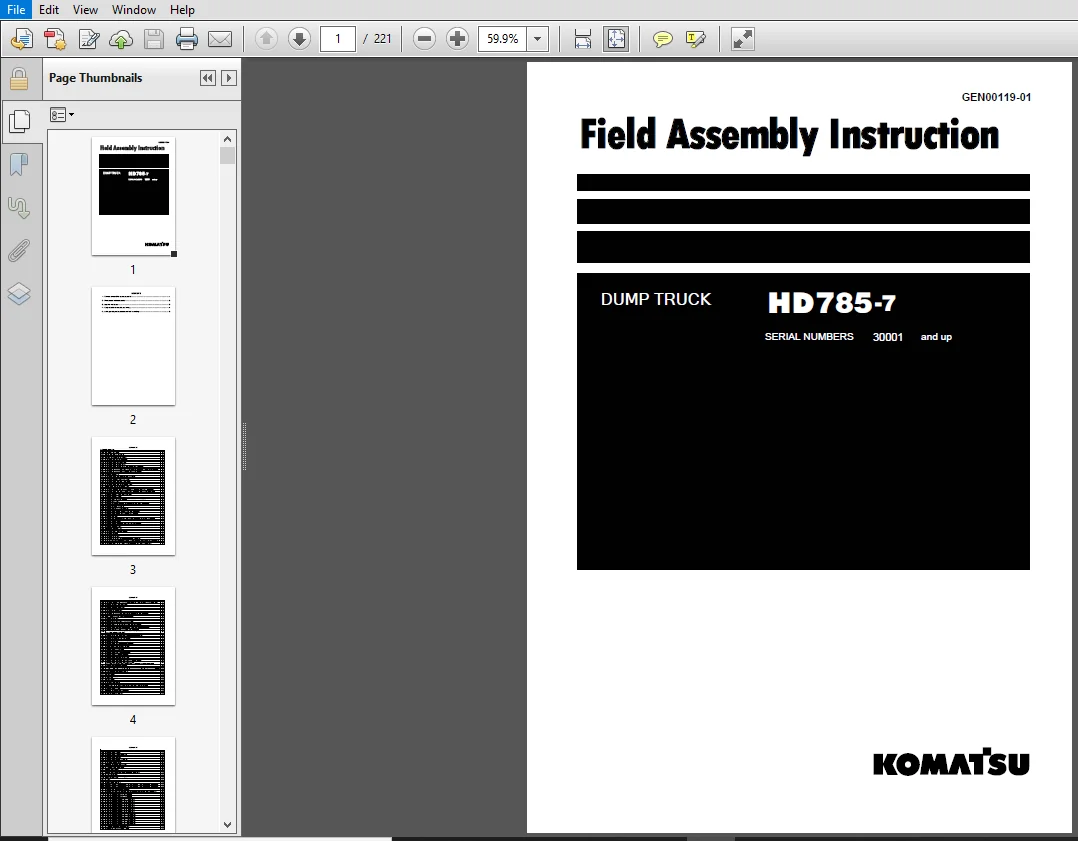
Komatsu HD785-7 Dump Truck Field Assembly Instruction Manual 30001 and up – PDF DOWNLOAD
Original price was: $39.95.$18.95Current price is: $18.95.
Komatsu HD785-7 Dump Truck Field Assembly Instruction Manual
SERIAL NUMBERS 30001 and up
Book Code: GEN00119-01
Instant PDF Download
Available immediately
Save to Your Device
Download & keep forever
Antivirus Scanned
100% virus-free
Trusted Worldwide
175,000+ customers
Description
Komatsu HD785-7 Dump Truck Field Assembly Instruction Manual
FILE DETAILS:
Komatsu HD785-7 Dump Truck Field Assembly Instruction Manual
Brands: Komatsu
Equipment Type: Dump Truck
Manuals Type: Field Assembly Instruction Manual
Machine Model: HD785-7
Serial Number: 30001 and up
Book Code: GEN00119-01
Language: English
Pages: 221
File Format: Portable Document Format (PDF)
KOMATSU HD785-7 DUMP TRUCK FIELD ASSEMBLY INSTRUCTION MANUAL 30001 AND UP – PDF DOWNLOAD:
IMAGES PREVIEW OF THE MANUAL:
TABLE OF CONTENTS:
Komatsu HD785-7 Dump Truck Field Assembly Instruction Manual
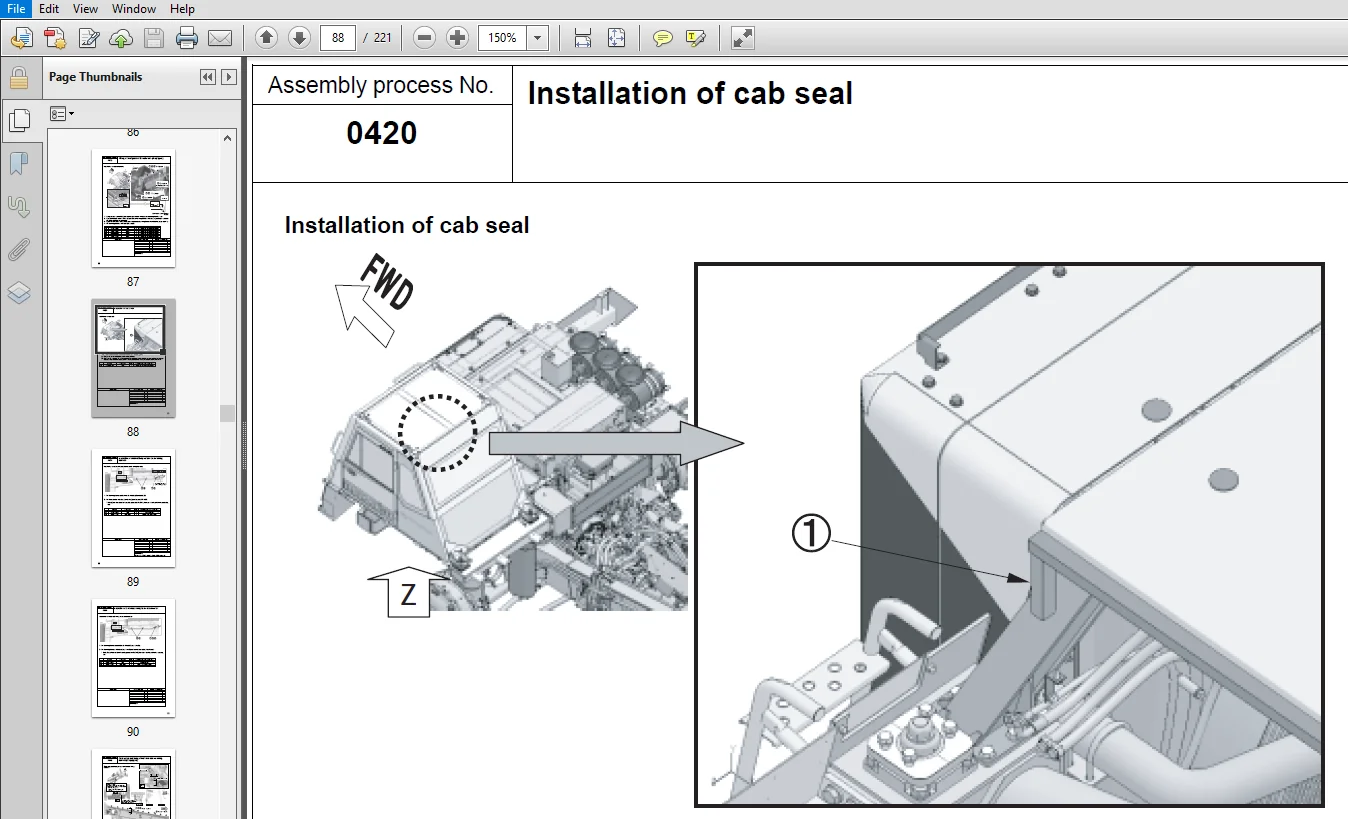
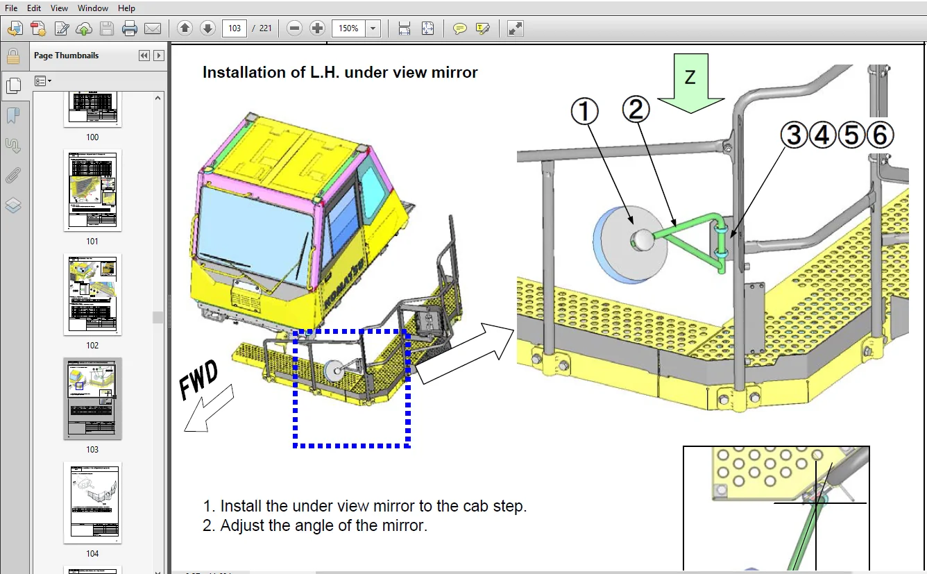
COVER...........................................................................................................................................................  1
CONTENTS........................................................................................................................................................  2
1. Outline of division (Only main components)...................................................................................................................  8
2. Dimensions of main components................................................................................................................................  9
3. Layout of work space......................................................................................................................................... 10
4. Rough schedule of assembly and welding....................................................................................................................... 11
5. List of jigs, tools, and consumables for field assembling.................................................................................................... 16
6. Assembly process No..........................................................................................................................................  0
	No. 0010 Oil, grease, and coolant........................................................................................................................... 23
	No. 0020 Levels of oil, grease, and coolant................................................................................................................. 24
	No. 0030 Positioning rear axle assembly..................................................................................................................... 25
	No. 0040 Slinging and moving of bare machine................................................................................................................ 26
	No. 0050 Connection of rod and rear suspension.............................................................................................................. 27
	No. 0060 Positioning bare machine........................................................................................................................... 28
	No. 0070 Connection of rear axle cooling hose............................................................................................................... 29
	No. 0080 Connection of rear axle brake hose................................................................................................................. 30
	No. 0085 Connection of rear axle brake hose (ASR specification: If equipped)................................................................................ 31
	No. 0086 Connection of valve sub-assembly wiring harness (ASR specification: If equipped)................................................................... 32
	No. 0087 Connection and fixing of piping going to rear axle (Sand terrain/ASR specification: If equipped)................................................... 33
	No. 0090 Connection and fixing of rear grease piping and supply of grease................................................................................... 34
	No. 0100 Preparation for installing front axle.............................................................................................................. 35
	No. 0110 Installation of front axle......................................................................................................................... 36
	No. 0120 Connection of front axle suspension pressure sensor................................................................................................ 37
	No. 0125 Connection of front axle wheel speed sensor (ABS specification: If equipped)....................................................................... 38
	No. 0130 Connection of steering cylinder and tie rod........................................................................................................ 39
	No. 0140 Connection of front axle brake cooling hoses....................................................................................................... 40
	No. 0150 Connection of front axle brake hoses............................................................................................................... 41
	No. 0160 Connection of front axle auto suspension piping.................................................................................................... 42
	No. 0165 Fixing of front axle auto suspension piping........................................................................................................ 43
	No. 0166 Fixing of front axle auto grease piping (If equipped: Auto grease specification)................................................................... 44
	No. 0167 Connection of left front axle auto grease piping (If equipped: Auto grease specification).......................................................... 45
	No. 0168 Connection of right front axle auto grease piping (If equipped: Auto grease specification)......................................................... 46
	No. 0170 Installation of bumper and front axle steps........................................................................................................ 47
	No. 0171 Installation of front axle step (EU specification)................................................................................................. 48
	No. 0173 Installation of front axle step.................................................................................................................... 49
	No. 0174 Installation of front axle step: Diagonal ladder specification (If equipped)....................................................................... 50
	No. 0180 Installation of tire and wheel assembly............................................................................................................ 51
	No. 0190 Installation of drive shaft........................................................................................................................ 52
	No. 0200 Installation of oil quick charge box (If equipped: Oil quick charge specification)................................................................. 53
	No. 0260 Installation of fuel tank wiring harness cover..................................................................................................... 54
	No. 0270 Installation of toolbox and tool kit............................................................................................................... 55
	No. 0275 Installation of fuel tank step (If equipped)....................................................................................................... 56
	No. 0280 Installation of rear support....................................................................................................................... 57
	No. 0281 Installation of rear support (Muffler specification: If equipped).................................................................................. 58
	No. 0282 Installation of rear support (ABS specification: If equipped)...................................................................................... 59
	No. 0283 Installation of rear support (Sand terrain specification: If equipped)............................................................................. 60
	No. 0290 Installation of muffler............................................................................................................................ 61
	No. 0291 Installation of muffler (Body heating-less/Exhaust selector box specification: If equipped)........................................................ 62
	No. 0300 Installation of fire prevention cover.............................................................................................................. 63
	No. 0310 Installation of front support...................................................................................................................... 64
	No. 0315 Installation of front support (Fog lamp specification: If equipped)................................................................................ 65
	No. 0317 Installation of front support (Fog lamp, beacon lamp, HID headlamp specification: If equipped)..................................................... 66
	No. 0320 Installation of steering valve..................................................................................................................... 67
	No. 0330 Preparation for installing cab..................................................................................................................... 68
	No. 0340 Installation of cab................................................................................................................................ 69
	No. 0345 Connection of ABS piping (If equipped)............................................................................................................. 70
	No. 0350 Connection of column............................................................................................................................... 71
	No. 0355 Installation of washer tank........................................................................................................................ 72
	No. 0370 Connection of cab wiring........................................................................................................................... 73
	No. 0375 Connection of cab wiring (ASR/ABS specification: If equipped)...................................................................................... 74
	No. 0376 Connection of engine prelubrication harness to cab (If equipped: Engine prelubrication specification).............................................. 75
	No. 0377 Connection and fixing of engine compartment lamp wiring harness (If equipped)...................................................................... 76
	No. 0378 Connection of auto grease harness to cab (If equipped: Auto grease specification).................................................................. 77
	No. 0379 Connection of engine stop harness to cab (If equipped: Engine emergency stop specification)........................................................ 78
	No. 0380 Installation and fixing of steering hoses.......................................................................................................... 79
	No. 0385 Fixing of air conditioner drain hose............................................................................................................... 80
	No. 0390 Installation of steering hose cover................................................................................................................ 81
	No. 0395 Connection of air conditioner and heater hoses..................................................................................................... 82
	No. 0400 Connection of cab floor wiring..................................................................................................................... 83
	No. 0405 Fixing of ASR/ABS wiring harness (If equipped)..................................................................................................... 84
	No. 0406 Connection and fixing of ABS wiring harness (ABS specification: If equipped)....................................................................... 85
	No. 0410 Installation of cover under cab.................................................................................................................... 86
	No. 0415 Wiring of front glass with heater wire (If equipped)............................................................................................... 87
	No. 0420 Installation of cab seal........................................................................................................................... 88
	No. 0430 Installation of ambient temperature sensor wiring harness.......................................................................................... 89
	No. 0440 Installation of undercab wiring harness connector.................................................................................................. 90
	No. 0445 Connection and fixing of rear view camera wiring harness (if equipped)............................................................................. 91
	No. 0451 Installation of hand rail and mirror to the R.H. platform assembly................................................................................. 92
	No. 0470 Installation of right fender....................................................................................................................... 93
	No. 0472 Installation of right fender (If equipped: Body heating-less muffler specification)................................................................ 94
	No. 0475 Installation of fuel tank quick charge-less hose (If equipped)..................................................................................... 95
	No. 0476 Installation of fuel tank quick chargeless hose: Muffler specification (If equipped: muffler specification)........................................ 96
	No. 0481 Assembly of diagonal ladder (if equipped).......................................................................................................... 97
	No. 0482 Installation of cab step: Diagonal ladder specification (if equipped).............................................................................. 98
	No. 0483 Installation of diagonal ladder 1 (if equipped).................................................................................................... 99
	No. 0484 Installation of diagonal ladder 2 (if equipped)....................................................................................................100
	No. 0485 Installation of diagonal ladder 3 (if equipped)....................................................................................................101
	No. 0489 Installation of cab step...........................................................................................................................102
	No. 0491 Installation of L.H. under view mirror (If equipped)...............................................................................................103
	No. 0500 Installation of fire extinguisher (If equipped)....................................................................................................104
	No. 0511 Installing radio antenna and fixing its cable......................................................................................................105
	No. 0520 Installation of L.H. fender........................................................................................................................106
	No. 0530 Installation of left side mudguard.................................................................................................................107
	No. 0540 Installation of grille guard.......................................................................................................................108
	No. 0550 Installation of left payload lamp (If equipped)....................................................................................................109
	No. 0555 Installation of left side lamp (If equipped).......................................................................................................110
	No. 0560 Installation of right payload lamp (If equipped)...................................................................................................111
	No. 0565 Installation of right side lamp (If equipped)......................................................................................................112
	No. 0570 Installation of left fender side lamp wiring harness (If equipped).................................................................................113
	No. 0580 Installation of right fender side lamp wiring harness (If equipped)................................................................................114
	No. 0581 Installation of right fender side lamp wiring harness. (If equipped: Body heating-less muffler, exhaust gas selector box muffler specification)....115
	No. 0590 Installation of KOMTRAX (If equipped)..............................................................................................................116
	No. 0595 Fixing of ORBCOMM antenna (If equipped)............................................................................................................117
	No. 0597 Connection and fixing of harness and hose going to auto grease pump -1 (If equipped: Auto grease specification)....................................118
	No. 0598 Connection and fixing of harness and hose going to auto grease pump - 2 (If equipped: Auto grease specification)...................................119
	No. 0600 Removal of hoist cylinder fixing bracket...........................................................................................................120
	No. 0610 Connection of hoist cylinder piping................................................................................................................121
	No. 0620 Welding of body....................................................................................................................................122
	No. 0630 Sticking of body decal.............................................................................................................................123
	No. 0640 Supply of oil......................................................................................................................................124
	No. 0650 Slinging of body...................................................................................................................................125
	No. 0660 Installation of hinge pin..........................................................................................................................126
	No. 0670 Connecting hoist cylinder..........................................................................................................................127
	No. 0680 Hoist cylinder grease piping.......................................................................................................................128
	No. 0685 Fixing of auto grease piping to body (If equipped: Auto grease specification)......................................................................129
	No. 0700 Installation of field welding protection cover.....................................................................................................130
	No. 0710 Installation of body mount.........................................................................................................................131
	No. 0720 Procedure for adjusting body mount shim............................................................................................................132
	No. 0730 Field welding of exhaust tube......................................................................................................................133
	No. 0740 Assembly of body heater cover......................................................................................................................134
	No. 0770 Installation of poke ejector.......................................................................................................................135
	No. 0780 Installation of poke ejector storage pin...........................................................................................................136
	No. 0790 Installation of body mudguard......................................................................................................................137
	No. 0800 Installation of body lock pin......................................................................................................................138
	No. 0810 Installation of transmission underguard............................................................................................................139
	No. 0830 Installation of front handle.......................................................................................................................140
	No. 0850 Connection of dump sensor..........................................................................................................................141
	No. 0860 Procedure for adjusting dump sensor................................................................................................................142
	No. 0870 Calibrating dump control...........................................................................................................................143
	No. 0880 Adjustment of optical axis of light................................................................................................................144
	No. 0900 Bleeding air from brake............................................................................................................................145
	No. 0901 Bleeding air from brake of ASR specification (ASR specification: If equipped)......................................................................146
	No. 0905 Bleeding air from ABS circuit (ABS specification: If equipped).....................................................................................147
	No. 0910 Adjusting suspension...............................................................................................................................148
	No. 0920 Charging air conditioner with refrigerant..........................................................................................................149
	No. 0930 Fitting of floating seal...........................................................................................................................150
	No. 0950 Painting...........................................................................................................................................151
	No. 0960 Touchup............................................................................................................................................152
	No. 1000 Sticking of front axle decal.......................................................................................................................153
	No. 1020-1 Operating procedure of prelubrication system (If equipped: Engine prelubrication specification)..................................................154
	No. 1020-2 Operating procedure of prelubrication system (If equipped: Engine prelubrication specification)..................................................155
	No. 1100 Installation of chocks (If equipped)...............................................................................................................156
	No. 1200 Installation of radiator curtain (If equipped).....................................................................................................157
	No. 1300 Installation and connection of beacon lamp (If equipped: Yellow beacon lamp specification).........................................................158
	No. 1400 Assembly of power ladder step -1 (If equipped).....................................................................................................159
	No. 1410 Assembly of power ladder step -2 (If equipped).....................................................................................................160
	No. 1420 Assembly of power ladder step -3 (If equipped).....................................................................................................161
	No. 1430 Assembly of power ladder main part -1 (If equipped)................................................................................................162
	No. 1440 Assembly of power ladder main part -2 (If equipped)................................................................................................163
	No. 1450 Assembly of power ladder main part -3 (If equipped)................................................................................................164
	No. 1460 Assembly of power ladder main part -4 (If equipped)................................................................................................165
	No. 1470 Assembly of power ladder main part -5 (If equipped)................................................................................................166
	No. 1480 Assembly of power ladder main part -6 (If equipped)................................................................................................167
	No. 1490 Assembly of power ladder main part -7 (If equipped)................................................................................................168
	No. 1500 Assembly of power ladder main part -8 (If equipped)................................................................................................169
	No. 1510 Assembly of power ladder main part -9 (If equipped)................................................................................................170
	No. 1520 Assembly of power ladder main part -10 (If equipped)...............................................................................................171
	No. 1530 Assembly of power ladder main part -11 (If equipped)...............................................................................................172
	No. 1540 Assembly of power ladder main part -12 (If equipped)...............................................................................................173
	No. 1550 Assembly of power ladder main part -13 (If equipped)...............................................................................................174
	No. 1560 Assembly of power ladder main part -14 (If equipped)...............................................................................................175
	No. 1570 Assembly of power ladder main part -15 (If equipped)...............................................................................................176
	No. 1580 Assembly of power ladder main part -16 (If equipped)...............................................................................................177
	No. 1590 Refilling power ladder with oil....................................................................................................................178
	No. 1600 Adjustment of power ladder operating time..........................................................................................................179
	No. 1610 Installation of additional under view mirror.......................................................................................................180
No. 7. Adjustment procedure.....................................................................................................................................  0
	No. T-0010 Bleeding air from fuel circuit 1 (If equipped: Extra low-grade fuel specification)...............................................................181
	No. T-0020 Bleeding air from fuel circuit 2 (If equipped: Extra low-grade fuel specification)...............................................................182
	No. T-0030 Setting of machine monitor.......................................................................................................................183
	No. T-0040 Selection of machine model.......................................................................................................................184
	No. T-0050 Selection of optional component..................................................................................................................185
	No. T-0060 Selection of option..............................................................................................................................186
	No. T-0070 Option setting/no-setting selection screen - Saving of change of option selection................................................................187
	No. T-0080 OFF setting of corrosion resistor with maintenance monitor.......................................................................................188
	No. T-0090 Adjustment of body positioner sensor.............................................................................................................189
	No. T-0100 Deletion of electrical system fault history (1)..................................................................................................190
	No. T-0110 Deletion of electrical system fault history (2)..................................................................................................191
No. 8. Welding procedure........................................................................................................................................  0
	No. C-0010 Preparation of welding body......................................................................................................................192
	No. C-0020 Assembly of split body (1/2).....................................................................................................................193
	No. C-0030 Assembly of split body (2/2).....................................................................................................................194
	No. C-0040 Tack welding body................................................................................................................................195
	No. C-0050 Welding body (1/2)...............................................................................................................................196
	No. C-0060 Welding body (2/2)...............................................................................................................................197
	No. C-0070 Welding body instruction (1/2)...................................................................................................................198
	No. C-0080 Welding body instruction (2/2)...................................................................................................................199
	No. C-0090 Turn over the body...............................................................................................................................200
	No. C-0100 Welding body protector (1/2).....................................................................................................................201
	No. C-0110 Welding body protector (2/2).....................................................................................................................202
	No. C-0120 Finishing and painting welded parts of body......................................................................................................203
	No. C-0130 Welding front body mount bracket.................................................................................................................204
Appendix........................................................................................................................................................  0
	Field assembly inspection report............................................................................................................................206
PLEASE NOTE:
- This is not a physical manual but a digital manual – meaning no physical copy will be couriered to you. The manual can be yours in the next 2 mins as once you make the payment, you will be directed to the download page IMMEDIATELY.
- This is the same manual used by the dealers inorder to diagnose your vehicle of its faults.
- Require some other service manual or have any queries: please WRITE to us at [email protected]


