KOMATSU HD785-7 DUMP TRUCK SERVICE REPAIR MANUAL – PDF DOWNLOAD
Original price was: $85.95.$26.95Current price is: $26.95.
- KOMATSU HD785-7 DUMP TRUCK SERVICE REPAIR MANUAL
- SERIAL NUMBERS A10001 & UP
- PUBLICATION NUMBER:CEBM019012
Description
KOMATSU HD785-7 DUMP TRUCK SERVICE REPAIR MANUAL
KOMATSU HD785-7 DUMP TRUCK SERVICE REPAIR MANUAL – PDF DOWNLOAD:
IMAGE PREVIEW:
DESCRIPTION:
KOMATSU HD785-7 DUMP TRUCK SERVICE REPAIR MANUAL
This shop manual contains the necessary technical information for services performed in a workshop. For ease of understanding, the manual is divided into the following sections.
00. Index and foreword
This section explains the shop manuals list, table of contents, safety, and basic information.
01. Specification
This section explains the specifications of the machine.
10. Structure, function and maintenance standard
This section explains the structure, function, and maintenance standard values of each component. The structure and function sub-section explains the structure and function of each component. It serves not only to give an understanding of the structure, but also serves as reference material for troubleshooting. The maintenance standard sub-section explains the criteria and remedies for disassembly and service.
20. Standard value table
This section explains the standard values for new machine and judgement criteria for testing, adjusting, and troubleshooting. This standard value table is used to check the standard values in testing and adjusting and to judge parts in troubleshooting.
30. Testing and adjusting
This section explains measuring instruments and measuring methods for testing and adjusting, and method of adjusting each part. The standard values and judgement criteria for testing and adjusting are explained in Testing and adjusting.
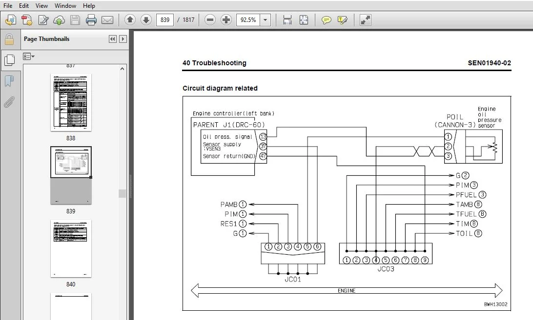
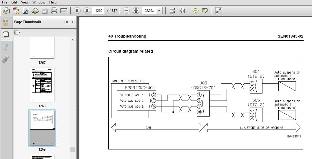
40. Troubleshooting
This section explains how to find out failed parts and how to repair them. The troubleshooting is divided by failure modes. The S mode of the troubleshooting related to the engine may be also explained in the Chassis volume and Engine volume. In this case, see the Chassis volume.
50. Disassembly and assembly
This section explains the special tools and procedures for removing, installing, disassembling, and assembling each component, as well as precautions for them. In addition, tightening torque and quantity and weight of coating material, oil, grease, and coolant necessary for the work are also explained.
90. Diagrams and drawings (chassis volume)/Repair and replacement of parts (engine volume)
Chassis volume
This section gives hydraulic circuit diagrams and electrical circuit diagrams.
Engine volume
This section explains the method of reproducing, repairing, and replacing parts.
TABLE OF CONTENTS:
KOMATSU HD785-7 DUMP TRUCK SERVICE REPAIR MANUAL
COVER...................................................................................................................................................................   1
00 Index and foreword...................................................................................................................................................   3
	Index...............................................................................................................................................................   3
		Composition of shop manual......................................................................................................................................   4
		Table of contents...............................................................................................................................................   6
	Foreword and general information....................................................................................................................................  23
		Safety notice...................................................................................................................................................  24
		How to read the shop manual.....................................................................................................................................  29
		Explanation of terms for maintenance standard...................................................................................................................  31
		Handling of electric equipment and hydraulic component..........................................................................................................  33
		Handling of connectors newly used for engines...................................................................................................................  42
		How to read electric wire code..................................................................................................................................  45
		Precautions when carrying out operation.........................................................................................................................  48
		Method of disassembling and connecting push-pull type coupler...................................................................................................  51
		Standard tightening torque table................................................................................................................................  54
		Conversion table................................................................................................................................................  58
01 Specification........................................................................................................................................................  65
	Specification and technical data....................................................................................................................................  65
		Specification drawing...........................................................................................................................................  66
		Specifications..................................................................................................................................................  68
		Weight table....................................................................................................................................................  71
		Fuel, coolant and lubricants....................................................................................................................................  72
10 Structure, function and maintenance standard.........................................................................................................................  77
	Engine and cooling system...........................................................................................................................................  77
		Radiator, brake, torque converter oil cooler, aftercooler, steering, hoist oil cooler...........................................................................  78
		Fuel system.....................................................................................................................................................  80
	Power train, Part 1.................................................................................................................................................  83
		Power train skeleton............................................................................................................................................  84
		Output shaft....................................................................................................................................................  86
		Drive shaft.....................................................................................................................................................  88
		Torque converter and transmission hydraulic piping..............................................................................................................  90
		Brake cooling oil control valve (BCV)...........................................................................................................................  92
		Torque converter................................................................................................................................................  93
		Torque converter valve.......................................................................................................................................... 101
		Transmission.................................................................................................................................................... 104
		Transmission control valve...................................................................................................................................... 132
		ECMV............................................................................................................................................................ 134
		Lubricating oil amount selector valve........................................................................................................................... 141
	Power train, Part 2................................................................................................................................................. 145
		Axle............................................................................................................................................................ 146
		Differential.................................................................................................................................................... 148
		Final drive..................................................................................................................................................... 149
		Wheels.......................................................................................................................................................... 150
	Steering system..................................................................................................................................................... 153
		Steering column................................................................................................................................................. 154
		Steering linkage................................................................................................................................................ 155
	Brake system........................................................................................................................................................ 159
		Brake piping.................................................................................................................................................... 160
		Brake valve..................................................................................................................................................... 162
		Secondary brake valve........................................................................................................................................... 165
		Accumulator charge valve........................................................................................................................................ 166
		Accumulator..................................................................................................................................................... 170
		Slack adjuster.................................................................................................................................................. 172
		Brake, parking brake............................................................................................................................................ 176
		Parking brake solenoid.......................................................................................................................................... 182
		Retarder control valve.......................................................................................................................................... 183
		Exhaust brake................................................................................................................................................... 184
	Undercarriage and frame............................................................................................................................................. 187
		Suspension...................................................................................................................................................... 188
		Suspension cylinder............................................................................................................................................. 190
		Rear axle support............................................................................................................................................... 198
	Hydraulic system.................................................................................................................................................... 201
		Steering and hoist hydraulic piping............................................................................................................................. 202
		Steering, hoist filter (high pressure circuit).................................................................................................................. 204
		Dump body control............................................................................................................................................... 206
		Hydraulic tank.................................................................................................................................................. 208
		Steering valve.................................................................................................................................................. 209
		Crossover relief valve.......................................................................................................................................... 213
		Steering cylinder............................................................................................................................................... 214
		Steering control valve.......................................................................................................................................... 215
		Hoist valve..................................................................................................................................................... 224
		Dump control valve (EPC valve).................................................................................................................................. 230
		Hydraulic pump.................................................................................................................................................. 234
	Work equipment (Body)............................................................................................................................................... 239
		Auto greasing system............................................................................................................................................ 240
		Hoist cylinder.................................................................................................................................................. 251
	Cab and its attachments............................................................................................................................................. 253
		ROPS cab........................................................................................................................................................ 254
		Air conditioner................................................................................................................................................. 255
		Rear view monitor............................................................................................................................................... 264
		Controller related.............................................................................................................................................. 267
	Electrical system, Part 1........................................................................................................................................... 269
		Machine monitor system.......................................................................................................................................... 270
	Electrical system, Part 2........................................................................................................................................... 295
		Automatic shift control system.................................................................................................................................. 296
		Automatic emergency steering system............................................................................................................................. 316
		Automatic suspension system..................................................................................................................................... 320
		Retarder control system......................................................................................................................................... 323
		Battery disconnector switch..................................................................................................................................... 336
		Dump control lever.............................................................................................................................................. 340
	Electrical system, Part 3........................................................................................................................................... 345
		VHMS controller related......................................................................................................................................... 346
		ABS/ASR system.................................................................................................................................................. 372
		Altitude setting function....................................................................................................................................... 390
	Electrical system, Part 4........................................................................................................................................... 395
		Sensors, switches............................................................................................................................................... 396
20 Standard value table................................................................................................................................................. 415
	Standard service value table........................................................................................................................................ 415
		Standard value table for engine................................................................................................................................. 416
		Standard value table for machine................................................................................................................................ 418
30 Testing and adjusting................................................................................................................................................ 431
	Testing and adjusting, Part 1....................................................................................................................................... 431
		Testing and adjusting tools list................................................................................................................................ 433
		Testing engine speed............................................................................................................................................ 439
		Testing air supply pressure (boost pressure).................................................................................................................... 440
		Testing exhaust temperature..................................................................................................................................... 442
		Testing exhaust gas color....................................................................................................................................... 444
		Adjustment of valve clearance................................................................................................................................... 446
		Testing compression pressure.................................................................................................................................... 448
		Testing blow-by pressure........................................................................................................................................ 450
		Testing engine oil pressure..................................................................................................................................... 451
		Handling of fuel system devices................................................................................................................................. 452
		Releasing residual pressure from fuel system.................................................................................................................... 452
		Testing fuel pressure........................................................................................................................................... 453
		Reduced cylinder mode operation................................................................................................................................. 454
		No-injection cranking........................................................................................................................................... 454
		Testing leakage-from pressure limiter and return rate from injector............................................................................................. 455
		Bleeding air from fuel circuit (Standard spec.)................................................................................................................. 458
		Bleeding air from fuel circuit (Extra low-grade fuel spec.)..................................................................................................... 460
		Testing the fuel circuit for leakage............................................................................................................................ 462
		Replacement and adjustment of fan belt.......................................................................................................................... 463
		Testing and adjusting alternator belt tension................................................................................................................... 464
		Testing and adjusting air conditioner compressor belt........................................................................................................... 465
	Testing and adjusting, Part 2....................................................................................................................................... 467
		Testing torque converter stall speed............................................................................................................................ 469
		Testing power train oil pressure................................................................................................................................ 471
		Adjusting transmission speed sensor............................................................................................................................. 479
		Testing and adjusting brake oil pressure........................................................................................................................ 480
		Testing of accumulator nitrogen gas pressure and procedure for charging accumulator with nitrogen gas........................................................... 483
		Testing brake performance....................................................................................................................................... 487
		Bleeding air from brake circuit................................................................................................................................. 489
		Bleeding air from ASR circuit (if equipped)..................................................................................................................... 491
		Testing wear of front brake disc................................................................................................................................ 492
		Testing wear of rear brake disc................................................................................................................................. 493
		Method of releasing parking brake in an emergency............................................................................................................... 494
		Testing and adjusting front suspension cylinder................................................................................................................. 495
		Testing and adjusting rear suspension cylinder.................................................................................................................. 499
		Testing and adjusting front suspension cylinder (Automatic suspension specification)............................................................................ 503
		Testing and adjusting hydraulic pressure in steering, hoist circuit............................................................................................. 504
		Testing and adjusting oil pressure in dump EPC circuit.......................................................................................................... 507
		Air bleeding from steering cylinder............................................................................................................................. 508
		Procedure for raising dump body in emergency.................................................................................................................... 509
		Adjusting body positioner sensor................................................................................................................................ 510
		Handling of high voltage circuit of engine controller........................................................................................................... 512
		Adjusting transmission controller............................................................................................................................... 512
		Method for emergency escape at electrical system failure........................................................................................................ 513
	Testing and adjusting, Part 3....................................................................................................................................... 519
		Setting and adjusting of devices................................................................................................................................ 520
	Testing and adjusting, Part 4....................................................................................................................................... 533
		Special functions of machine monitor (EMMS)..................................................................................................................... 534
	Testing and adjusting, Part 5....................................................................................................................................... 603
		Opening ORBCOMM terminal........................................................................................................................................ 604
		VHMS controller initial setting procedure....................................................................................................................... 606
		Precautions for replacing VHMS controller....................................................................................................................... 631
		Pm Clinic check sheet........................................................................................................................................... 637
		Initial setting of payload meter................................................................................................................................ 641
		Setting of payload meter built in VHMS.......................................................................................................................... 642
40 Troubleshooting...................................................................................................................................................... 651
	Failure code table and fuse locations............................................................................................................................... 651
		Failure codes table............................................................................................................................................. 652
		Fuse locations.................................................................................................................................................. 668
	General information on troubleshooting.............................................................................................................................. 675
		Points to remember when troubleshooting......................................................................................................................... 676
		Sequence of events in troubleshooting........................................................................................................................... 677
		Check before troubleshooting.................................................................................................................................... 678
		Classification and procedures for troubleshooting............................................................................................................... 679
		Contents of troubleshooting table............................................................................................................................... 680
		Connection table for connector pin numbers...................................................................................................................... 682
		T- branch box and T- branch adapter table....................................................................................................................... 718
	Troubleshooting by failure code, Part 1............................................................................................................................. 723
		Failure code [1500L0] Dual engagement........................................................................................................................... 725
		Failure code [15B0NX] Transmission oil filter: Clogging......................................................................................................... 726
		Failure code [15F0KM] R → F shifting abuse 1: Mistake in operation.............................................................................................. 728
		Failure code [15F0MB] R → F shifting abuse 2: Mistake in operation.............................................................................................. 728
		Failure code [15F7KM] Forward clutch disk abuse: Mistake in operation or setting................................................................................ 729
		Failure code [15G0MW] R clutch: Slipping........................................................................................................................ 730
		Failure code [15G7KM] Reverse clutch disk abuse: Mistake in operation or setting................................................................................ 732
		Failure code [15H0MW] Hi clutch: Slipping....................................................................................................................... 734
		Failure code [15J0MW] Lo clutch: Slipping....................................................................................................................... 736
		Failure code [15K0MW] 1st clutch: Slipping...................................................................................................................... 738
		Failure code [15L0MW] 2nd clutch: Slipping...................................................................................................................... 740
		Failure code [15M0MW] 3rd clutch: Slipping...................................................................................................................... 742
		Failure code [15N0MW] 4th clutch: Slipping...................................................................................................................... 744
		Failure code [15SBL1] R clutch solenoid: Fill signal is ON when command current is OFF.......................................................................... 746
		Failure code [15SBMA] R clutch solenoid: Malfunction............................................................................................................ 748
		Failure code [15SCL1] Hi clutch solenoid: Fill signal is ON when command current is OFF......................................................................... 750
		Failure code [15SCMA] Hi clutch solenoid: Malfunction........................................................................................................... 754
		Failure code [15SDL1] Lo clutch solenoid: Fill signal is ON when command current is OFF......................................................................... 756
		Failure code [15SDMA] Lo clutch solenoid: Malfunction........................................................................................................... 760
		Failure code [15SEL1] 1st clutch solenoid: Fill signal is ON when command current is OFF........................................................................ 762
		Failure code [15SEMA] 1st clutch solenoid: Malfunction.......................................................................................................... 766
	Troubleshooting by failure code, Part 2............................................................................................................................. 769
		Failure code [15SFL1] 2nd clutch solenoid: Fill signal is ON when command current is OFF........................................................................ 771
		Failure code [15SFMA] 2nd clutch solenoid: Malfunction.......................................................................................................... 774
		Failure code [15SGL1] 3rd clutch solenoid: Fill signal is ON when command current is OFF........................................................................ 776
		Failure code [15SGMA] 3rd clutch solenoid: Malfunction.......................................................................................................... 780
		Failure code [15SHL1] 4th clutch solenoid: Fill signal is ON when command current is OFF........................................................................ 782
		Failure code [15SHMA] 4th clutch solenoid: Malfunction.......................................................................................................... 786
		Failure code [15SJMA] Lockup clutch solenoid: Malfunction....................................................................................................... 788
		Failure code [2F00KM] Parking brake: Mistake in operation or setting............................................................................................ 789
		Failure code [2G42ZG] Accumulator: Oil pressure reduction (Front)............................................................................................... 792
		Failure code [2G43ZG] Accumulator: Oil pressure reduction (Rear)................................................................................................ 792
		Failure code [989A00] Engine over run prevention command signal: Operating...................................................................................... 793
		Failure code [989D00] Rear section tipping over alarm: Alarm is activated....................................................................................... 793
		Failure code [A570NX] Engine oil filter: Clogging............................................................................................................... 794
		Failure code [AA10NX] Air cleaner element: Clogging............................................................................................................. 796
		Failure code [AB00L4] Alternator: Failure on battery charge circuit (R terminal signal is present and engine is stopped)........................................ 798
		Failure code [AB00MA] Alternator: Malfunction................................................................................................................... 800
		Failure code [AB00MB] Alternator: Failure on battery charge circuit (Absence of R terminal signal and detection error).......................................... 802
		Failure code [B@BAZG] Abnormal lowering of engine oil pressure: Lowering of oil pressure........................................................................ 804
		Failure code [B@BAZK] Engine oil: Level too low................................................................................................................. 806
		Failure code [B@BCNS] Engine: Overheat.......................................................................................................................... 808
		Failure code [B@BCZK] Lowering of radiator coolant: Lowering of level........................................................................................... 810
		Failure code [B@BFZK] Lowering of fuel level.................................................................................................................... 812
		Failure code [B@C6NS] Brake cooling oil: Overheating (Front).................................................................................................... 814
		Failure code [B@C7NS] Brake cooling oil: Overheating (Rear)..................................................................................................... 815
		Failure code [B@CENS] Overheating of torque converter oil....................................................................................................... 816
		Failure code [B@GAZK] Battery electrolyte level: Lowering of level.............................................................................................. 817
		Failure code [B@JANS] Steering oil: Overheat.................................................................................................................... 818
	Troubleshooting by failure code, Part 3............................................................................................................................. 821
		Failure code [CA111] Engine controller (Left bank): Internal abnormality........................................................................................ 824
		Failure code [CB111] Engine controller (Right bank): Internal abnormality....................................................................................... 826
		Failure code [CA115] Abnormal engine Ne and Bkup speed sensors (Left bank): Abnormal speed sensor signal........................................................ 828
		Failure code [CB115] Abnormal engine Ne and Bkup speed sensors (Right bank): Abnormal speed sensor signal....................................................... 829
		Failure code [CA122] Charge pressure sensor too high (At left bank only): Excessively high voltage detected..................................................... 830
		Failure code [CA123] Charge pressure sensor too low (At left bank only): Excessively low voltage detected....................................................... 832
		Failure code [CA131] Throttle sensor high error (At left bank only)............................................................................................. 834
		Failure code [CA132] Throttle sensor low error (At left bank only).............................................................................................. 837
		Failure code [CA135] Oil pressure sensor too high (At left bank only): Excessively high voltage detected........................................................ 838
		Failure code [CA141] Oil pressure sensor too low (At left bank only): Excessively low voltage detected.......................................................... 840
		Failure code [CA144] Coolant temperature sensor too high: Excessively high voltage detected..................................................................... 842
		Failure code [CA145] Coolant temperature sensor too low (At left bank only): Excessively low voltage detected................................................... 844
		Failure code [CA153] Charge temperature sensor too high (At left bank only): Excessively high voltage detected.................................................. 846
		Failure code [CA154] Charge temperature sensor too low (At left bank only): Excessively low voltage detected.................................................... 848
		Failure code [CA187] Sensor power supply (2) abnormally low level (Left bank): Low voltage detection............................................................ 850
		Failure code [CB187] Sensor power supply (2) abnormally low level (Right bank): Low voltage detection........................................................... 850
		Failure code [CA212] Engine oil temperature sensor abnormally high level (At left bank only): High voltage detection............................................ 852
		Failure code [CA213] Engine oil temperature sensor abnormally low level (At left bank only): Low voltage detection.............................................. 854
		Failure code [CA221] Atmospheric pressure sensor too high (At left bank only): Excessively high voltage detected................................................ 856
		Failure code [CA222] Atmospheric pressure sensor too low (At left bank only): Excessively low voltage detected.................................................. 858
		Failure code [CA227] Sensor power source (2) too high (Left bank): Excessively high voltage detected............................................................ 860
		Failure code [CB227] Sensor power supply (2) abnormally high level (Right bank): High voltage detection......................................................... 862
		Failure code [CA234] Engine over speed (At left bank only): Excessively high speed.............................................................................. 864
		Failure code [CA238] Abnormal power source for Ne speed sensor (At left bank only): Excessively low voltage detected............................................ 866
		Failure code [CB238] Abnormal power source for Ne speed sensor (At right bank only): Excessively low voltage detected........................................... 868
		Failure code [CA263] Fuel temperature sensor too high (Left bank): Excessively high voltage detected............................................................ 870
		Failure code [CB263] Fuel temperature sensor too high (Right bank): Excessively high voltage detected........................................................... 872
		Failure code [CA265] Fuel temperature sensor abnormally low level (Left bank): Low voltage detection............................................................ 874
		Failure code [CB265] Fuel temperature sensor abnormally low level (Right bank): Low voltage detection........................................................... 874
		Failure code [CA271] PCV1 short circuit (Left bank): Short circuit.............................................................................................. 875
		Failure code [CB271] PCV1 short circuit (Right bank): Short circuit............................................................................................. 876
		Failure code [CA272] PCV1 disconnection (Left bank): Disconnection.............................................................................................. 877
		Failure code [CB272] PCV1 disconnection (Right bank): Disconnection............................................................................................. 878
		Failure code [CA273] PCV2 short circuit (Left bank): Short circuit.............................................................................................. 879
		Failure code [CB273] PCV2 short circuit (Right bank): Short circuit............................................................................................. 880
		Failure code [CA274] PCV2 disconnection (Left bank): Disconnection.............................................................................................. 881
		Failure code [CB274] PCV2 disconnection (Right bank): Disconnection............................................................................................. 882
	Troubleshooting by failure code, Part 4............................................................................................................................. 885
		Failure code [CA322] Injector No. 1 (L/B No.1) system disconnection or short circuit (Left bank): Disconnection, short circuit.................................. 888
		Failure code [CA323] Injector No. 5 (L/B No.5) system disconnection or short circuit (Left bank): Disconnection, short circuit.................................. 890
		Failure code [CA324] Injector No. 3 (L/B No.3) system disconnection or short circuit (Left bank): Disconnection, short circuit.................................. 892
		Failure code [CA325] Injector No. 6 (L/B No.6) system disconnection or short circuit (Left bank): Disconnection, short circuit.................................. 894
		Failure code [CA331] Injector No. 2 (L/B No.2) system disconnection or short circuit (Left bank): Disconnection, short circuit.................................. 896
		Failure code [CA332] Injector No. 4 (L/B No.4) system disconnection or short circuit (Left bank): Disconnection, short circuit.................................. 898
		Failure code [CA342] Engine controller data mismatch (Left bank): Mismatch...................................................................................... 900
		Failure code [CB342] Engine controller data mismatch (Right bank): Mismatch..................................................................................... 900
		Failure code [CA351] Abnormal injector drive circuit (Left bank): Abnormal circuit.............................................................................. 902
		Failure code [CB351] Injector drive circuit abnormality (Right bank): Circuit abnormality....................................................................... 904
		Failure code [CA352] Sensor power supply (1) abnormally low level (Left bank): Low voltage detection............................................................ 906
		Failure code [CB352] Sensor power supply (1) abnormally low level (Right bank): Low voltage detection........................................................... 906
		Failure code [CA386] Sensor power supply (1) abnormally high level (Left bank): High voltage detection.......................................................... 908
		Failure code [CB386] Sensor power supply (1) abnormally high level (Right bank): High voltage detection......................................................... 910
		Failure code [CA431] Trouble in idle validation switch.......................................................................................................... 912
		Failure code [CA432] Idle validation action error............................................................................................................... 916
		Failure code [CA441] Power supply voltage abnormally low level (Left bank): Low voltage detection............................................................... 917
		Failure code [CB441] Power supply voltage abnormally low level (Right bank): Low voltage detection.............................................................. 917
		Failure code [CA442] Power supply voltage abnormally high level (Left bank): High voltage detection............................................................. 918
		Failure code [CB442] Power supply voltage abnormally high level (Right bank): High voltage detection............................................................ 918
		Failure code [CA449] Common rail abnormally high pressure (2) (Left bank): Abnormally high pressure occurrence.................................................. 919
		Failure code [CB449] Common rail abnormally high pressure (2) (Right bank): Abnormally high pressure occurrence................................................. 919
		Failure code [CA451] Common rail pressure sensor too high (Left bank): Excessively high voltage detected........................................................ 920
		Failure code [CB451] Common rail pressure sensor abnormally high level (Right bank): High voltage detection..................................................... 922
		Failure code [CA452] Common rail pressure sensor abnormally low level (Left bank): Abnormally low voltage detection............................................. 924
		Failure code [CB452] Common rail pressure sensor abnormally low level (Right bank): Abnormally low voltage detection............................................ 924
		Failure code [CA553] Common rail pressure too high (1) (Left bank): Excessively high pressure detected.......................................................... 925
		Failure code [CB553] Common rail pressure too high (1) (Right bank): Excessively high pressure detected......................................................... 926
		Failure code [CA554] In-range error in common rail pressure sensor (Left bank): In-range error.................................................................. 927
		Failure code [CB554] In-range error in common rail pressure sensor (Right bank): In-range error................................................................. 927
		Failure code [CA559] Loss of pressure feed from supply pump (1) (Left bank): Loss of pressure feed detected..................................................... 928
		Failure code [CB559] Loss of pressure feed from supply pump (1) (Right bank): Loss of pressure feed detected.................................................... 932
		Failure code [CA689] Abnormal engine Ne speed sensor (Left bank): Abnormal signal............................................................................... 936
		Failure code [CB689] Abnormal engine Ne speed sensor (Right bank): Abnormal signal.............................................................................. 938
		Failure code [CA691] Intake air temperature sensor abnormally high level (At left bank only): High voltage detection............................................ 940
		Failure code [CA692] Intake air temperature sensor abnormally low level (At left bank only): Low voltage detection.............................................. 942
		Failure code [CA731] Abnormal engine Bkup speed sensor phase (Left bank): Abnormal phase........................................................................ 943
		Failure code [CB731] Abnormal engine Bkup speed sensor phase (Right bank): Abnormal phase....................................................................... 943
	Troubleshooting by failure code, Part 5............................................................................................................................. 945
		Failure code [CA757] Loss of all engine controller data (Left bank): Loss of all data........................................................................... 947
		Failure code [CB757] Loss of all engine controller data (Right bank): Loss of all data.......................................................................... 947
		Failure code [CA778] Abnormal engine Bkup speed sensor (Left bank): Abnormal Bkup signal........................................................................ 948
		Failure code [CB778] Engine Bkup speed sensor abnormality (Right bank): Bkup signal error....................................................................... 950
		Failure code [CA781] Inter-multicontroller communication error (Left bank): Communication error................................................................. 952
		Failure code [CB781] Inter-multicontroller communication error (Right bank): Communication error................................................................ 954
		Failure code [CA1257] Multicontroller distinction wiring harness key error (Left bank): Distinction error....................................................... 955
		Failure code [CB1257] Multicontroller distinction wiring harness key error (Right bank): Distinction error...................................................... 956
		Failure code [CB1548] Injector #7 (R/B #1) system disconnection/short circuit (Right bank): Disconnection/Short circuit......................................... 958
		Failure code [CB1549] Injector #8 (R/B #2) system disconnection/short circuit (Right bank): Disconnection/Short circuit......................................... 960
		Failure code [CB1551] Injector #10 (R/B #4) system disconnection/short circuit (Right bank): Disconnection/Short circuit........................................ 962
		Failure code [CB1552] Injector #11 (R/B #5) system disconnection/short circuit (Right bank): Disconnection/Short circuit........................................ 964
		Failure code [CB1553] Injector #12 (R/B #6) system disconnection/short circuit (Right bank): Disconnection/Short circuit........................................ 966
		Failure code [CB1622] Injector #9 (R/B #3) system disconnection/short circuit (Right bank): Disconnection/Short circuit......................................... 968
		Failure code [CA1633] KOMNET abnormality (Left bank): Communication error....................................................................................... 970
		Failure code [CA2185] Throttle sensor supply voltage high error................................................................................................. 972
		Failure code [CA2186] Throttle sensor power supply low error.................................................................................................... 974
		Failure code [CA2249] Loss of pressure feed from supply pump (2) (Left bank): Loss of pressure feed detected.................................................... 975
		Failure code [CB2249] Loss of pressure feed from supply pump (2) (Right bank): Loss of pressure feed detected................................................... 975
		Failure code [CA2555] Intake heater relay voltage low error (Left bank)......................................................................................... 976
		Failure code [CA2556] Intake heater relay voltage high error (Left bank)........................................................................................ 978
	Troubleshooting by failure code, Part 6............................................................................................................................. 981
		Failure code [D180KA] Preheating relay output system: Disconnection............................................................................................. 983
		Failure code [D180KB] Preheating relay output system: Grounding fault........................................................................................... 984
		Failure code [D180KY] Preheating relay output system: Hot short circuit......................................................................................... 986
		Failure code [D19HKB] Stop lamp relay output system: Short circuit.............................................................................................. 988
		Failure code [D1EFKA] Pre-lubrication start relay output system: Disconnection.................................................................................. 990
		Failure code [D1EFKB] Pre-lubrication start relay output system: Grounding fault................................................................................ 992
		Failure code [D1EFKY] Pre-lubrication start relay output system: Hot short circuit.............................................................................. 994
		Failure code [DAF9KM] Wrong connection of connector............................................................................................................. 996
		Failure code [DAFRKR] CAN communication error (Machine monitor): Communication error............................................................................ 997
		Failure code [DAQ0KK] Transmission controller direct power supply: Lowering of source voltage...................................................................1000
		Failure code [DAQ0KT] Transmission controller nonvolatile memory: Abnormality in controller.....................................................................1002
		Failure code [DAQ2KK] Transmission controller solenoid power source: Power source voltage too low...............................................................1003
		Failure code [DAQ9KQ] Transmission controller: Disagreement of model selection..................................................................................1004
		Failure code [DAQRKR] Abnormality in CAN communication (Transmission)...........................................................................................1004
		Failure code [DAQRMA] Transmission controller option setting: Malfunction.......................................................................................1005
		Failure code [DB10KT] Retarder controller nonvolatile memory: Abnormality in controller.........................................................................1005
		Failure code [DB12KK] Retarder controller solenoid power source: Power source system trouble....................................................................1006
		Failure code [DB13KK] Retarder controller battery direct power source: Power source voltage too low.............................................................1008
		Failure code [DB19KQ] Disagreement of model selection (Retarder controller).....................................................................................1010
		Failure code [DB1RKR] CAN communication (retarder controller): Communication disabled...........................................................................1011
		Failure code [DB1RMA] Disagreement of option setting (Retarder controller)......................................................................................1014
		Failure code [DB2RKR] CAN communication (engine controller): Communication disabled.............................................................................1015
		Failure code [dB2RKR] CAN communication (engine controller): Communication disabled.............................................................................1018
		Failure code [DBB0KK] (or VHMS_LED display: "n9" → "01") VHMS controller: Low source voltage (input)............................................................1022
		Failure code [DBB0KQ] (or VHMS_LED display: "nF" → "11") (VHMS controller: Disagreement of model selection signals).............................................1024
		Failure code [DBB3KK] (or VHMS_LED display: "n9" → "05") VHMS controller battery power supply: Low source voltage (input).......................................1026
		Failure code [DBB5KP] (or VHMS_LED display: "n9" → "04") (VHMS controller 5 V power supply output: Low output voltage)..........................................1028
		Failure code [DBB6KP] (or VHMS_LED display: "n9" → "02") (VHMS controller 24 V power supply output: Low output voltage).........................................1030
		Failure code [DBB7KP] (or VHMS_LED display: "n9" → "03") (VHMS controller 12 V power supply output: Low output voltage).........................................1032
		Failure code [DBBQKR] (or VHMS_LED display: "n8" → "02") VHMS controller CAN communication: Defective communication (Abnormality in target component system)....1034
		Failure code [DBBRKR] Abnormality in CAN communication (VHMS)...................................................................................................1036
		Failure code [DBC2KK] ABS controller solenoid power source: Power source system trouble.........................................................................1038
		Failure code [DBC3KK] ABS controller battery direct power source: Power source voltage too low..................................................................1040
		Failure code [DBC9KQ] Disagreement of model selection (ABS controller)..........................................................................................1042
		Failure code [DBCRKR] Abnormality in CAN communication (ABS)....................................................................................................1042
		Failure code [DBCRMA] Disagreement of option setting (ABS controller)...........................................................................................1043
		Failure code [DBG2KK] Solenoid power supply: Low voltage........................................................................................................1044
		Failure code [DBG3KK] Battery direct power supply: Low voltage..................................................................................................1046
		Failure code [DBG9KQ] Model selection signal: Abnormal..........................................................................................................1048
		Failure code [DDD7KX] Trouble in travel speed setting switch system: Out of input signal range..................................................................1050
		Failure code [DDD8KA] ARSC system switch system: Disconnection..................................................................................................1052
		Failure code [DDD8KB] ARSC system switch system: Short circuit..................................................................................................1054
		Failure code [DDD9KA] ABS system switch system: Disconnection...................................................................................................1056
		Failure code [DDD9KB] ABS system switch system: Short circuit...................................................................................................1058
		Failure code [DDDAKA] ASR system switch: Disconnection..........................................................................................................1060
		Failure code [DDDAKB] ASR system switch: Short circuit..........................................................................................................1062
		Failure code [DDE2KB] Engine oil pressure switch error: Grounding fault.........................................................................................1064
		Failure code [DDE2L6] Engine oil pressure switch error: Disconnection or hot short circuit......................................................................1066
		Failure code [DDP6L4] Service brake pressure switch trouble (Rear)..............................................................................................1068
		Failure code [DDTHKA] Hi clutch fill switch: Disconnection......................................................................................................1070
		Failure code [DDTJKA] Lo clutch fill switch: Disconnection......................................................................................................1072
		Failure code [DDTKKA] 1st clutch fill switch: Disconnection.....................................................................................................1074
		Failure code [DDTLKA] 2nd clutch fill switch: Disconnection.....................................................................................................1076
		Failure code [DDTMKA] 3rd clutch fill switch: Disconnection.....................................................................................................1078
		Failure code [DDTNKA] R clutch fill switch: Disconnection.......................................................................................................1080
		Failure code [DDTPKA] 4th clutch fill switch: Disconnection.....................................................................................................1082
		Failure code [DF10KA] Gear shift lever: Disconnection...........................................................................................................1084
		Failure code [DF10KB] Gear shift lever: Short circuit...........................................................................................................1087
		Failure code [DGE5KX] (or VHMS_LED display: "n4" → "01") (Atmospheric temperature sensor: Out of input signal range)............................................1090
		Failure code [DGF1KX] Transmission oil temperature sensor: Out of input signal range............................................................................1092
		Failure code [DGR2KB] Trouble in retarder oil temperature sensor (rear wheel) system (Disconnection and short circuit)..........................................1094
		Failure code [DGR2KZ] Trouble in retarder oil temperature sensor (rear wheel) system (Ground fault).............................................................1096
		Failure code [DGR4KB] Trouble in retarder oil temperature sensor (front wheel) system (Disconnection and short circuit).........................................1098
		Failure code [DGR4KZ] Trouble in retarder oil temperature sensor (front wheel) system (Ground fault)............................................................1100
		Failure code [DGR6KX] Steering oil temperature sensor: Input signal out of range................................................................................1102
		Failure code [DGT1KX] Torque converter oil temperature sensor: Out of input signal range........................................................................1104
	Troubleshooting by failure code, Part 7.............................................................................................................................1107
		Failure code [DGT5KA] (or VHMS_LED display: "n3" → "12") Left bank exhaust temperature sensor system (Front): Disconnection.....................................1109
		Failure code [dGT5KA] (or VHMS_LED display: "n3" → "22") Left bank exhaust temperature sensor system (Rear): Disconnection......................................1112
		Failure code [DGT5KB] (or VHMS_LED display: "n3" → "11") Left bank exhaust temperature sensor system (Front): Short circuit.....................................1115
		Failure code [dGT5KB] (or VHMS_LED display: "n3" → "21") Left bank exhaust temperature sensor system (Rear): Short circuit......................................1118
		Failure code [DGT6KA] (or VHMS_LED display: "n3" → "24") Right bank exhaust temperature sensor system (Front): Disconnection....................................1121
		Failure code [dGT6KA] (or VHMS_LED display: "n3" → "26") Right bank exhaust temperature sensor system (Rear): Disconnection.....................................1124
		Failure code [DGT6KB] (or VHMS_LED display: "n3" → "23") Right bank exhaust temperature sensor system (Front): Short circuit....................................1127
		Failure code [dGT6KB] (or VHMS_LED display: "n3" → "25") Right bank exhaust temperature sensor system (Rear): Short circuit.....................................1130
		Failure code [DHE5KB] (or VHMS_LED display: "n3" → "32") (Blow-by pressure sensor: Short circuit)...............................................................1134
		Failure code [DHE5KY] (or VHMS_LED display: "n3" → "31") (Blow-by pressure sensor: Short circuit with power supply line)........................................1136
		Failure code [DHP4KY] (or VHMS_LED display: "n5" → "44") Suspension pressure sensor system: Short circuit (Right front).........................................1138
		Failure code [DHP4KZ] (or VHMS_LED display: "n5" → "43") Suspension pressure sensor system: Disconnection or ground fault (Right front).........................1140
		Failure code [DHP5KY] (or VHMS_LED display: "n5" → "54") Suspension pressure sensor system: Short circuit (Left front)..........................................1142
		Failure code [DHP5KZ] (or VHMS_LED display: "n5" → "53") Suspension pressure sensor system: Disconnection or ground fault (Left front)..........................1144
		Failure code [DHP6KA] Suspension pressure sensor system: Disconnection (Right rear).............................................................................1146
		Failure code [DHP6KX] Failure in suspension pressure sensor system trouble: Out of input signal range (Right rear)..............................................1148
		Failure code [DHP6KY] (or VHMS_LED display: "n5" → "64") Suspension pressure sensor system: Short circuit (Right rear)..........................................1150
		Failure code [DHP6KZ] (or VHMS_LED display: "n5" → "63") Suspension pressure sensor system: Disconnection or ground fault (Right rear)..........................1152
		Failure code [DHP7KA] Suspension pressure sensor system: Disconnection (Left rear)..............................................................................1154
		Failure code [DHP7KX] Failure in suspension pressure sensor system: Out of input signal range (Left rear).......................................................1156
		Failure code [DHP7KY] (or VHMS_LED display: "n5" → "74") Suspension pressure sensor system: Short circuit (Left rear)...........................................1158
		Failure code [DHP7KZ] (or VHMS_LED display: "n5" → "73") Suspension pressure sensor system: Disconnection or ground fault (Left rear)...........................1160
		Failure code [DHT5KX] Torque converter oil pressure sensor: Out of input signal range...........................................................................1162
		Failure code [DHT5L6] Torque converter oil pressure sensor: Disagreement of run and stop condition with signal..................................................1164
		Failure code [DHU2KX] Front accumulator oil pressure sensor: Out of input signal range..........................................................................1166
		Failure code [DHU3KX] Rear accumulator oil pressure sensor: Out of input signal range...........................................................................1168
		Failure code [DHU6KX] Trouble in ABS control valve pressure sensor (Front right)................................................................................1170
		Failure code [DHU7KX] Trouble in ABS control valve pressure sensor (Front left).................................................................................1172
		Failure code [DHU8KX] Trouble in ABS control valve pressure sensor (Rear right).................................................................................1174
		Failure code [DHU9KX] Trouble in ABS control valve pressure sensor (Rear left)..................................................................................1176
		Failure code [DJF1KA] Fuel level sensor: Disconnection..........................................................................................................1178
		Failure code [DK30KX] Steering angle potentiometer: Trouble (Disconnection).....................................................................................1179
		Failure code [DK51L5] Trouble in retarder lever potentiometer and RVS...........................................................................................1180
		Failure code [DK52KX] Failure in hoist lever potentiometer 1: Out of input signal range.........................................................................1184
		Failure code [DK53L8] Failure in hoist lever potentiometer 2: Disagreement of analog signal.....................................................................1186
		Failure code [DK54KX] Body positioner sensor: Out of input signal range.........................................................................................1188
		Failure code [DKD0L6] Failure in steering angle speed sensor....................................................................................................1190
		Failure code [DKH0KX] Pitch angle sensor: Out of input signal range.............................................................................................1192
		Failure code [DKH1KX] (or VHMS_LED display: "n4" → "33") Pitch angle sensor: Abnormality........................................................................1194
		Failure code [DLF1KA] Transmission input shaft speed sensor: Disconnection......................................................................................1196
		Failure code [DLF1LC] Transmission input shaft speed sensor: Disagreement of revolution speed signal............................................................1198
		Failure code [DLF2KA] Transmission intermediate shaft speed sensor: Disconnection...............................................................................1200
		Failure code [DLF2LC] Transmission intermediate shaft speed sensor: Disagreement of revolution speed signal.....................................................1202
	Troubleshooting by failure code, Part 8.............................................................................................................................1205
		Failure code [DLF6KA] Disconnection in wheel speed sensor (Front right).........................................................................................1208
		Failure code [DLF6L3] Trouble in wheel speed sensor (Front right)...............................................................................................1210
		Failure code [DLF7KA] Disconnection in wheel speed sensor (Front left)..........................................................................................1212
		Failure code [DLF7L3] Trouble in wheel speed sensor (Front left)................................................................................................1214
		Failure code [DLF8KA] Wheel speed sensor: Disconnection (Rear right)............................................................................................1216
		Failure code [DLF8L3] Wheel speed sensor: Disconnection (Rear right)............................................................................................1218
		Failure code [DLF8LC] Wheel speed sensor: Trouble (Rear right)..................................................................................................1220
		Failure code [DLF8MA] Wheel speed sensor: Disconnection (Rear right)............................................................................................1220
		Failure code [DLF9KA] Wheel speed sensor: Disconnection (Rear left).............................................................................................1222
		Failure code [DLF9L3] Wheel speed sensor: Trouble (Rear left)...................................................................................................1224
		Failure code [DLF9LC] Wheel speed sensor: Trouble (Rear left)...................................................................................................1226
		Failure code [DLF9MA] Wheel speed sensor: Disconnection (Rear left).............................................................................................1226
		Failure code [DLT3KA] Transmission output shaft speed sensor: Disconnection.....................................................................................1228
		Failure code [DLT3LC] Transmission output shaft speed sensor: Disagreement of revolution speed signal...........................................................1230
		Failure code [DLT4KA] Transmission output shaft speed sensor: Disconnection.....................................................................................1232
		Failure code [DLT4MA] Transmission output shaft speed sensor: Disconnection.....................................................................................1234
		Failure code [DUM7KY] Pre-lubrication operation lamp output abnormality: Hot short circuit......................................................................1236
		Failure code [DUM7KZ] Pre-lubrication operation lamp output abnormality: Disconnection or grounding fault.......................................................1238
		Failure code [DV00KB] Buzzer output: Short circuit..............................................................................................................1240
		Failure code [DW2AKA] Main pressure variable valve output: Disconnection........................................................................................1242
		Failure code [DW2AKB] Main pressure variable valve output circuit: Ground fault.................................................................................1244
		Failure code [DW2AKY] Main pressure variable valve output circuit: Hot short....................................................................................1246
		Failure code [DW2AL1] Main pressure variable valve: Defective reset.............................................................................................1248
		Failure code [DW2ALH] Main pressure variable valve: Malfunction.................................................................................................1250
		Failure code [DW2BKA] Main oil level selector valve output: Disconnection.......................................................................................1251
		Failure code [DW2BKB] Main oil level selector valve output circuit: Ground fault................................................................................1252
		Failure code [DW2BKY] Main oil level selector valve output circuit: Hot short...................................................................................1254
		Failure code [DW2BL1] Main oil level selector valve: Defective reset............................................................................................1256
		Failure code [DW2BLH] Main oil level selector valve: Malfunction................................................................................................1258
		Failure code [DW2CKA] Transmission lubrication variable valve output: Disconnection.............................................................................1259
		Failure code [DW2CKB] Transmission lubrication variable valve output circuit: Ground fault......................................................................1260
		Failure code [DW2CKY] Transmission lubrication variable valve output circuit: Hot short.........................................................................1262
		Failure code [DW2CL1] Transmission lubrication variable valve: Defective reset..................................................................................1264
		Failure code [DW2CLH] Transmission lubrication variable valve: Malfunction......................................................................................1266
		Failure code [DW35KZ] Failure in output system of auto suspension solenoid 1: Disconnection or short circuit....................................................1268
		Failure code [DW36KZ] Failure in output system of auto suspension solenoid 2: Disconnection or short circuit....................................................1270
		Failure code [DW71KZ] Exhaust brake output system trouble (Disconection/Ground fault/Hot short).................................................................1272
		Failure code [DW72KZ] Kick-out solenoid output system trouble: Disconnection or short circuit...................................................................1274
		Failure code [DW73KZ] Failure in hoist select valve output system: Disconnection or short circuit...............................................................1276
		Failure code [DW78KZ] Brake cooling valve (BCV) (rear wheel) output system trouble: Disconnection or short circuit..............................................1278
		Failure code [DWNBK4] ASR shut-off valve: Trouble (Valve keeps operating).......................................................................................1280
		Failure code [DWNBKA] ASR shut-off valve output circuit: Disconnection..........................................................................................1282
		Failure code [DWNBKB] ASR shut-off valve output circuit: Ground fault...........................................................................................1284
		Failure code [DWNBKY] ASR shut-off valve output circuit: Short circuit..........................................................................................1286
		Failure code [DWNBMA] ASR shut-off valve: Trouble (Valve does not operate)......................................................................................1286
		Failure code [DWNDKZ] Trouble in ABS cut-off valve (Front) system...............................................................................................1288
		Failure code [DWNDMA] Defective ABS cut-off valve (Front).......................................................................................................1290
		Failure code [DWNEKZ] Trouble in ABS cut-off valve (Rear) system................................................................................................1292
		Failure code [DWNEMA] Defective ABS cut-off valve (Rear)........................................................................................................1294
	Troubleshooting by failure code, Part 9.............................................................................................................................1297
		Failure code [DX11K4] Rear brake proportional pressure reducing solenoid valve: Out of control..................................................................1300
		Failure code [DX11KA] Rear brake proportional pressure reducing solenoid valve output circuit: Disconnection....................................................1302
		Failure code [DX11KB] Rear brake proportional pressure reducing solenoid valve: Short circuit...................................................................1303
		Failure code [DX11KY] Rear brake proportional pressure reducing solenoid valve: Short circuit to power source line..............................................1304
		Failure code [DX11MA] Rear brake proportional pressure reducing solenoid valve: Malfunction.....................................................................1306
		Failure code [DX12K4] Front brake proportional pressure reducing solenoid valve: Out of control.................................................................1308
		Failure code [DX12KA] Front brake proportional pressure reducing solenoid valve output circuit: Disconnection...................................................1310
		Failure code [DX12KB] Front brake proportional pressure reducing solenoid valve: Short circuit..................................................................1311
		Failure code [DX12KY] Front brake proportional pressure reducing solenoid valve: Short circuit to power source line.............................................1312
		Failure code [DX12MA] Front brake proportional pressure reducing solenoid valve: Malfunction....................................................................1314
		Failure code [DX13KA] Output circuit of hoist EPC valve: Disconnection..........................................................................................1316
		Failure code [DX13KB] Output circuit of hoist EPC valve: Short circuit..........................................................................................1318
		Failure code [DX13KY] Output circuit of hoist EPC valve: Short circuit with power source line...................................................................1320
		Failure code [DX17K4] ASR proportional pressure reducing solenoid valve (right): Trouble (Valve keeps operating)................................................1322
		Failure code [DX17KA] ASR proportional pressure reducing solenoid valve (right) output circuit: Disconnection...................................................1324
		Failure code [DX17KB] ASR proportional pressure reducing solenoid valve (right) output circuit: Ground fault....................................................1326
		Failure code [DX17KY] ASR proportional pressure reducing solenoid valve (right) output circuit: Short circuit...................................................1328
		Failure code [DX17MA] ASR proportional pressure reducing solenoid valve (right): Trouble (Valve does not operate)...............................................1328
		Failure code [DX18K4] ASR proportional pressure reducing solenoid valve (left): Trouble (Valve keeps operating).................................................1330
		Failure code [DX18KA] ASR proportional pressure reducing solenoid valve (left) output circuit: Disconnection....................................................1332
		Failure code [DX18KB] ASR proportional pressure reducing solenoid valve (left) output circuit: Ground fault.....................................................1334
		Failure code [DX18KY] ASR proportional pressure reducing solenoid valve (left) output circuit: Short circuit....................................................1336
		Failure code [DX18MA] ASR proportional pressure reducing solenoid valve (left): Trouble (Valve does not operate)................................................1336
		Failure code [DX21KA] Disconnection in ABS control valve output circuit (Front right)...........................................................................1337
		Failure code [DX21KB] Ground fault in ABS control valve output circuit (Front right)............................................................................1338
		Failure code [DX21KY] Hot short in ABS control valve output circuit (Front right)...............................................................................1339
		Failure code [DX21MA] Defective ABS control valve (Front right).................................................................................................1340
		Failure code [DX22KA] Disconnection in ABS control valve output circuit (Front left)............................................................................1341
		Failure code [DX22KB] Ground fault in ABS control valve output circuit (Front left).............................................................................1342
		Failure code [DX22KY] Hot short in ABS control valve output circuit (Front left)................................................................................1343
		Failure code [DX22MA] Defective ABS control valve (Front left)..................................................................................................1344
		Failure code [DX23KA] Disconnection in ABS control valve output circuit (Rear right)............................................................................1345
		Failure code [DX23KB] Ground fault in ABS control valve output circuit (Rear right).............................................................................1346
		Failure code [DX23KY] Hot short in ABS control valve output circuit (Rear right)................................................................................1347
		Failure code [DX23MA] Defective ABS control valve (Rear right)..................................................................................................1348
		Failure code [DX24KA] Disconnection in ABS control valve output circuit (Rear left).............................................................................1349
		Failure code [DX24KB] Ground fault in ABS control valve output circuit (Rear left)..............................................................................1350
		Failure code [DX24KY] Hot short in ABS control valve output circuit (Rear left).................................................................................1351
		Failure code [DX24MA] Defective ABS control valve (Rear left)...................................................................................................1352
		Failure code [DX25MA] Defective ABS front wheel system control valve............................................................................................1353
		Failure code [DX26MA] Defective ABS rear wheel system control valve.............................................................................................1353
	Troubleshooting by failure code, Part 10............................................................................................................................1355
		Failure code [DXH1KA] Lockup clutch solenoid output circuit: Disconnection......................................................................................1357
		Failure code [DXH1KB] Lock-up clutch solenoid output circuit: Short circuit.....................................................................................1358
		Failure code [DXH1KY] Lockup clutch solenoid output circuit: Short circuit to power source line.................................................................1359
		Failure code [DXH2KA] Hi clutch solenoid output circuit: Disconnection..........................................................................................1360
		Failure code [DXH2KB] Hi clutch solenoid output circuit: Short circuit..........................................................................................1362
		Failure code [DXH2KY] Hi clutch solenoid output circuit: Short circuit to power source line.....................................................................1364
		Failure code [DXH3KA] Lo clutch solenoid output circuit: Disconnection..........................................................................................1368
		Failure code [DXH3KB] Lo clutch solenoid output circuit: Short circuit..........................................................................................1370
		Failure code [DXH3KY] Lo clutch solenoid output circuit: Short circuit in power source line.....................................................................1372
		Failure code [DXH4KA] 1st clutch solenoid output circuit: Disconnection.........................................................................................1376
		Failure code [DXH4KB] 1st clutch solenoid output circuit: Short circuit.........................................................................................1378
		Failure code [DXH4KY] 1st clutch solenoid output circuit: Short circuit to power source line....................................................................1380
		Failure code [DXH5KA] 2nd clutch solenoid output circuit: Disconnection.........................................................................................1384
		Failure code [DXH5KB] 2nd clutch solenoid output circuit: Short circuit.........................................................................................1386
		Failure code [DXH5KY] 2nd clutch solenoid output circuit: Short circuit in power source line....................................................................1388
		Failure code [DXH6KA] 3rd clutch solenoid output circuit: Disconnection.........................................................................................1392
		Failure code [DXH6KB] 3rd clutch solenoid output circuit: Short circuit.........................................................................................1394
		Failure code [DXH6KY] 3rd clutch solenoid output circuit: Short circuit to power source line....................................................................1396
		Failure code [DXH7KA] R clutch solenoid output circuit: Disconnection...........................................................................................1400
		Failure code [DXH7KB] R clutch solenoid output circuit: Short circuit...........................................................................................1402
		Failure code [DXH7KY] R clutch solenoid output circuit: Short circuit to power source line......................................................................1404
		Failure code [DXHHKA] 4th clutch solenoid output circuit: Disconnection.........................................................................................1406
		Failure code [DXHHKB] 4th clutch solenoid output circuit: Short circuit.........................................................................................1408
		Failure code [DXHHKY] 4th clutch solenoid output circuit: Short circuit to power source line....................................................................1410
		Failure code [F@BBZL] (or VHMS_LED display: "n3" → "38") (Blow-by pressure: High error..........................................................................1414
		Failure code [F@BYNS] (or VHMS_LED display "n3" → "61") Left front exhaust temperature sensor (1): Exhaust temperature abnormal rise............................1416
		Failure code [f@BYNS] (or VHMS_LED display "n3" → "71") Left rear exhaust temperature sensor (1): Exhaust temperature abnormal rise.............................1418
		Failure code [F@BZNS] (or VHMS_LED display "n3" → "81") Right front exhaust temperature sensor (1): Exhaust temperature abnormal rise...........................1420
		Failure code [f@BZNS] (or VHMS_LED display "n3" → "91") Right rear exhaust temperature sensor (1): Exhaust temperature abnormal rise............................1422
		Failure code [F@BYNR] (or VHMS_LED display "n3" → "62") Left front exhaust temperature sensor (2): Exhaust temperature abnormal rise............................1424
		Failure code [f@BYNR] (or VHMS_LED display "n3" → "72") Left rear exhaust temperature sensor (2): Exhaust temperature abnormal rise.............................1426
		Failure code [F@BZNR] (or VHMS_LED display "n3" → "82") Right front exhaust temperature sensor (2): Exhaust temperature abnormal rise...........................1428
		Failure code [f@BZNR] (or VHMS_LED display "n3" → "92") Right rear exhaust temperature sensor (2): Exhaust temperature abnormal rise............................1430
	Troubleshooting of electrical system (E-mode).......................................................................................................................1433
		Before troubleshooting of electric system.......................................................................................................................1435
		Contents of troubleshooting table...............................................................................................................................1436
		E-1 Engine does not start.......................................................................................................................................1437
		E-2 Automatic preheating does not operate.......................................................................................................................1440
		E-3 Machine monitor does not display all, when starting switch is turned ON.....................................................................................1444
		E-4 Machine monitor does not operate when starting switch is OFF................................................................................................1446
		E-5 Alarm buzzer does not sound.................................................................................................................................1448
		E-6 Alarm buzzer does not stop sounding.........................................................................................................................1450
		E-7 Gauges of machine monitor, caution lamps or character display section do not display properly...............................................................1451
		E-8 A selection of the display in character display section cannot be changed...................................................................................1453
		E-9 Power mode selecting function does not operate properly.....................................................................................................1456
		E-10 AISS function does not operate properly....................................................................................................................1457
		E-11 Seat belt caution lamp does not display properly...........................................................................................................1458
		E-12 Turn signal lamp or turning lamp (hazard lamp) do not work properly........................................................................................1459
		E-13 Night illumination (lighting) does not work properly.......................................................................................................1462
		E-14 Emergency steering does not operate........................................................................................................................1474
		E-15 Hoist lever does not operate normally......................................................................................................................1480
		E-16 Power supply system (Air conditioner does not operate).....................................................................................................1482
		E-17 Compressor and refrigerant system (Air is not cooled)......................................................................................................1484
		E-18 Blower motor system (Air does not come out or air flow is abnormal)........................................................................................1486
	Troubleshooting of hydraulic and mechanical system (H-mode).........................................................................................................1489
		Contents of troubleshooting table...............................................................................................................................1491
		H-1 Machine does not start......................................................................................................................................1492
		H-2 Machine does not travel smoothly (hunting)..................................................................................................................1494
		H-3 Lockup cannot be cancelled..................................................................................................................................1494
		H-4 Excessive shock when starting or shifting excessive.........................................................................................................1495
		H-5 Transmission does not shift up..............................................................................................................................1496
		H-6 Machine lacks power or speed when traveling.................................................................................................................1498
		H-7 Time lag is excessive when starting or shifting gear........................................................................................................1502
		H-8 Torque converter oil temperature is high....................................................................................................................1504
		H-9 Torque converter oil pressure is low........................................................................................................................1505
		H-10 Front brake is ineffective.................................................................................................................................1506
		H-11 Rear brake is ineffective..................................................................................................................................1507
		H-12 Steering wheel is heavy....................................................................................................................................1508
		H-13 Steering wheel does not work...............................................................................................................................1509
		H-14 Steering wheel vibrates....................................................................................................................................1510
		H-15 Dump body lifting speed is slow............................................................................................................................1511
		H-16 Dump body does not work....................................................................................................................................1512
		H-17 Excessive hydraulic drift of dump body.....................................................................................................................1513
	Troubleshooting of engine (S-mode)..................................................................................................................................1515
		Method of using troubleshooting charts..........................................................................................................................1517
		S-1 Starting performance is poor................................................................................................................................1520
		S-2 Engine does not start.......................................................................................................................................1521
		S-3 Engine does not pick up smoothly............................................................................................................................1524
		S-4 Engine stops during operations..............................................................................................................................1525
		S-5 Engine does not rotate smoothly.............................................................................................................................1526
		S-6 Engine lacks output (or lacks power)........................................................................................................................1527
		S-7 Exhaust smoke is black (incomplete combustion)..............................................................................................................1529
		S-8 Oil consumption is excessive (or exhaust smoke is blue).....................................................................................................1530
		S-9 Oil becomes contaminated quickly............................................................................................................................1531
		S-10 Fuel consumption is excessive..............................................................................................................................1532
		S-11 Oil is in coolant (or coolant spurts back or coolant level goes down)......................................................................................1533
		S-12 Oil pressure drops.........................................................................................................................................1534
		S-13 Oil level rises (Entry of coolant or fuel).................................................................................................................1535
		S-14 Coolant temperature becomes too high (overheating).........................................................................................................1536
		S-15 Abnormal noise is made.....................................................................................................................................1537
		S-16 Vibration is excessive.....................................................................................................................................1538
50 Disassembly and assembly.............................................................................................................................................1541
	General information on disassembly and assembly.....................................................................................................................1541
		How to read this manual.........................................................................................................................................1542
		Coating materials list..........................................................................................................................................1544
		Special tool list...............................................................................................................................................1547
		Sketches of special tools.......................................................................................................................................1550
	Engine and cooling system...........................................................................................................................................1557
		Removal and installation of fuel supply pump assembly...........................................................................................................1558
		Removal and installation of fuel injector assembly..............................................................................................................1560
		Removal and installation of cylinder head assembly..............................................................................................................1561
		Removal and installation of engine hood assembly................................................................................................................1574
		Removal and installation of radiator assembly...................................................................................................................1575
		Removal and installation of engine assembly.....................................................................................................................1584
		Removal and installation of engine front oil seal...............................................................................................................1589
		Removal and installation of engine rear oil seal................................................................................................................1592
	Power train, Part 1.................................................................................................................................................1597
		Removal and installation of front drive shaft...................................................................................................................1598
		Removal and installation of rear drive shaft....................................................................................................................1600
		Removal and installation of output shaft assembly...............................................................................................................1601
		Disassembly and assembly of damper assembly.....................................................................................................................1606
		Removal and installation of torque converter and transmission assembly..........................................................................................1608
		Disconnection and connection of torque converter assembly and transmission assembly.............................................................................1611
		Disassembly and assembly of torque converter PTO assembly.......................................................................................................1618
		Disassembly and assembly of transmission assembly...............................................................................................................1631
	Power train, Part 2.................................................................................................................................................1665
		Removal and installation of final drive carrier assembly........................................................................................................1666
		Disassembly and assembly of final drive carrier assembly........................................................................................................1668
		Removal and installation of differential assembly...............................................................................................................1670
		Disassembly and assembly of differential assembly...............................................................................................................1673
	Steering system.....................................................................................................................................................1687
		Removal and installation of steering cylinder assembly..........................................................................................................1688
		Disassembly and assembly of steering cylinder assembly..........................................................................................................1689
		Removal and installation of steering valve assembly.............................................................................................................1693
		Disassembly and assembly of steering valve assembly.............................................................................................................1694
	Brake system........................................................................................................................................................1707
		Removal and installation of front wheel hub and brake assembly..................................................................................................1708
		Disassembly and assembly of front wheel hub and brake assembly..................................................................................................1712
		Removal and installation of final drive and rear brake assembly.................................................................................................1720
		Disassembly and assembly of final drive and rear brake assembly.................................................................................................1722
	Undercarriage and frame.............................................................................................................................................1737
		Removal and installation of front wheel assembly................................................................................................................1738
		Removal and installation of rear wheel assembly.................................................................................................................1740
		Removal and installation of front suspension cylinder assembly..................................................................................................1742
		Disassembly and assembly of front suspension cylinder assembly (cylinder with buffer ring)......................................................................1744
		Removal and installation of king pin............................................................................................................................1747
		Removal and installation of rear suspension cylinder assembly...................................................................................................1749
		Disassembly and assembly of rear suspension cylinder assembly...................................................................................................1750
	Hydraulic system....................................................................................................................................................1755
		Removal and installation of hoist valve assembly................................................................................................................1756
		Disassembly and assembly of hoist valve assembly................................................................................................................1757
		Disassembly and assembly of hoist cylinder assembly.............................................................................................................1759
	Body................................................................................................................................................................1763
		Removal and installation of body assembly.......................................................................................................................1764
	Cab and its attachments.............................................................................................................................................1769
		Disassembly and assembly of operator’s seat assembly............................................................................................................1770
		Removal and installation of air conditioner unit assembly.......................................................................................................1780
	Electrical system...................................................................................................................................................1783
		Removal and installation of engine controller assembly..........................................................................................................1784
		Removal and installation of transmission controller assembly....................................................................................................1784
		Removal and installation of retarder controller assembly........................................................................................................1785
		Removal and installation of ABS controller assembly.............................................................................................................1785
		Removal and installation of VHMS controller assembly............................................................................................................1786
90 Diagrams and drawings................................................................................................................................................1789
	Hydraulic diagrams and drawings.....................................................................................................................................1789
		Power train hydraulic circuit diagram...........................................................................................................................1791
		Steering and hoist hydraulic circuit diagram....................................................................................................................1792
		Brake hydraulic circuit diagram.................................................................................................................................1793
		Brake hydraulic circuit diagram (ASR specification).............................................................................................................1794
		Brake hydraulic circuit diagram (ABS specification).............................................................................................................1795
		Brake hydraulic circuit diagram (ASR and ABS specification).....................................................................................................1796
	Electrical diagrams and drawings....................................................................................................................................1799
		Electrical circuit diagram for outside cab (1/3)................................................................................................................1801
		Electrical circuit diagram for outside cab (2/3)................................................................................................................1802
		Electrical circuit diagram for outside cab (3/3)................................................................................................................1803
		Electrical circuit diagram for inside cab (1/3).................................................................................................................1804
		Electrical circuit diagram for inside cab (2/3).................................................................................................................1805
		Electrical circuit diagram for inside cab (3/3).................................................................................................................1806
		Electrical circuit diagram for VHMS (If equipped)...............................................................................................................1807
		Electrical circuit diagram for ABS (Outside cab) (If equipped)..................................................................................................1808
		Electrical circuit diagram for ABS (Inside cab) (If equipped)...................................................................................................1809
		Electrical circuit diagram for ASR (If equipped)................................................................................................................1810
		Air conditioner electrical circuit diagram (If equipped)........................................................................................................1811
		Electrical circuit diagram for auto greasing (If equipped)......................................................................................................1812
		Connectors table and arrangement drawing........................................................................................................................1814
PLEASE NOTE:
⦁ This is the same manual used by the dealers to diagnose and troubleshoot your vehicle
⦁ You will be directed to the download page as soon as the purchase is completed. The whole payment and downloading process will take anywhere between 2-5 minutes
⦁ Need any other service / repair / parts manual, please feel free to contact [email protected] . We still have 50,000 manuals unlisted


