
Komatsu HD785-8E0 Dump Truck Field Assembly Instruction Manual GEN00209-02 – PDF DOWNLOAD
Original price was: $86.95.$28.95Current price is: $28.95.
Komatsu HD785-8E0 Dump Truck Field Assembly Instruction Manual GEN00209-02 – PDF DOWNLOAD
SERIAL NUMBERS 55001 and up
Description
Komatsu HD785-8E0 Dump Truck Field Assembly Instruction Manual GEN00209-02 – PDF DOWNLOAD
IMAGES PREVIEW OF THE MANUAL:
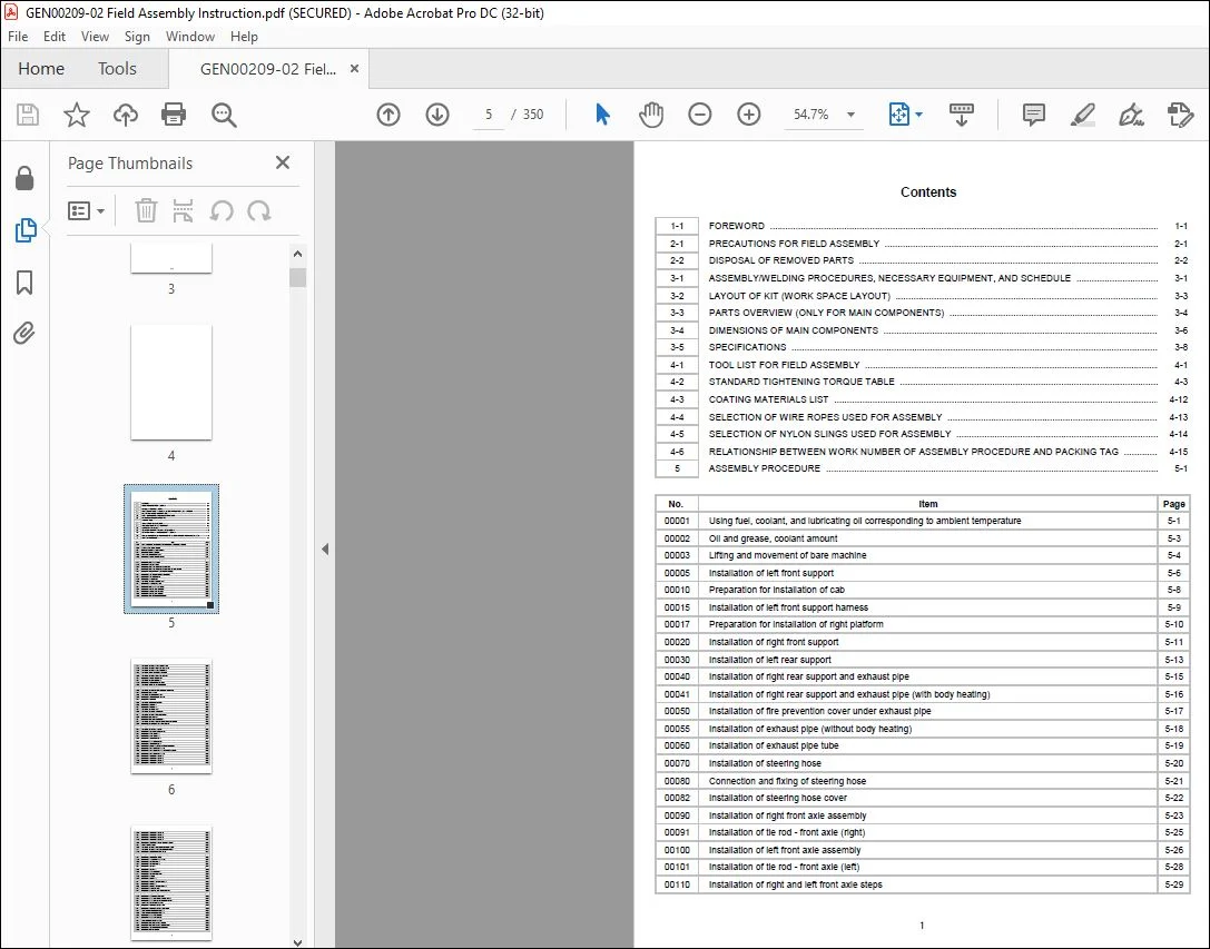
TABLE OF CONTENTS:
Komatsu HD785-8E0 Dump Truck Field Assembly Instruction Manual GEN00209-02 – PDF DOWNLOAD
00001 Using fuel, coolant, and lubricating oil corresponding to ambient temperature 5-1
00002 Oil and grease, coolant amount 5-3
00003 Lifting and movement of bare machine 5-4
00005 Installation of left front support 5-6
00010 Preparation for installation of cab 5-8
00015 Installation of left front support harness 5-9
00017 Preparation for installation of right platform 5-10
00020 Installation of right front support 5-11
00030 Installation of left rear support 5-13
00040 Installation of right rear support and exhaust pipe 5-15
00041 Installation of right rear support and exhaust pipe (with body heating) 5-16
00050 Installation of fire prevention cover under exhaust pipe 5-17
00055 Installation of exhaust pipe (without body heating) 5-18
00060 Installation of exhaust pipe tube 5-19
00070 Installation of steering hose 5-20
00080 Connection and fixing of steering hose 5-21
00082 Installation of steering hose cover 5-22
00090 Installation of right front axle assembly 5-23
00091 Installation of tie rod – front axle (right) 5-25
00100 Installation of left front axle assembly 5-26
00101 Installation of tie rod – front axle (left) 5-28
00110 Installation of right and left front axle steps 5-29
1
00120 Connection and fixing of left front axle sensor 5-30
00130 Connection and fixing of right front axle sensor 5-31
00135 Connection and fixing of left front axle hose 5-32
00140 Connection of front axle brake cooling hose 5-33
00145 Connection and fixing of right front axle hose 5-34
00150 Installation of left front support step 5-35
00160 Connection of rear propeller shaft 5-36
00170 Installation of rear propeller shaft guard 5-38
00180 Connection of cab – left accumulator hose 5-39
00183 Connection of cab brake hose 5-40
00185 Connection of brake hose under the air cleaner to CAB 5-41
00190 Installation of right fender 5-42
00191 Connection of right fender side lamp 5-43
00192 Installation of cover under right platform 5-44
00200 Installation of left fender 5-45
00201 Connection of left fender side lamp 5-46
00210 Installation of rear axle – 1 5-47
00220 Installation of rear axle – 2 5-49
00225 Connection of rear axle hose 5-51
00230 Connection of rear axle cooling hose 5-52
00232 Connection and fixing of rear axle harness 5-54
00235 Installation of right platform 5-55
00237 Installation of right platform mudguard 5-57
00250 Connection and fixing of rear suspension oil pressure sensor 5-58
00280 Installation of air conditioner hose fixing bracket 5-59
00281 Fixing of air conditioner drain hose 5-60
00290 Connection of radiator heater hose 5-61
00300 Installation of left payload meter harness 5-62
00350 Installation of radio antenna – 1 5-63
00360 Installation of radio antenna – 2 5-64
00370 Installation of cover under cab – 1 5-66
00372 Installation of mudguard under cab 5-67
00380 Installation of cover under cab – 2 5-68
00385 Installation of battery disconnect box (without jump start) 5-69
00400 Installation of diagonal ladder step – 1-1 5-70
00401 Installation of diagonal ladder step – 1-2 (shipping by travel) 5-72
00402 Installation of diagonal ladder step – 1-3 5-73
00410 Installation of diagonal ladder step – 2 5-74
00420 Installation of diagonal ladder step – 3 5-76
00430 Installation of diagonal ladder step – 4 5-78
00440 Installation of diagonal ladder step – 5 5-80
2
00445 Installation of diagonal ladder step – 6 5-82
00450 Installation of diagonal ladder step – 7 5-84
00460 Installation of diagonal ladder step – 8 5-86
00470 Installation of diagonal ladder step – 9 5-87
00480 Installation of diagonal ladder step – 10 (without radar) 5-89
00500 Fixing of catwalk mirror 5-90
00510 Connection and fixing of right fender side lamp harness 5-91
00520 Connection and fixing of left fender side lamp harness 5-92
00530 Installation of battery isolator cable cover 5-93
00550 Wiring of engine emergency stop box harness 5-94
00560 Installation of cover in front of cab 5-95
00570 Installation of step support in front of cab 5-96
00580 Installation of catwalk mount – 1 5-97
00590 Installation of catwalk mount – 2 5-98
00600 Installation of catwalk – 1 5-99
00601 Installation of catwalk – 2 5-100
00610 Installation of step in front of cab 5-101
00620 Installation of catwalk mount cover 5-103
00630 Installation of front tire 5-104
00640 Installation of rear tire – 1 5-106
00641 Installation of rear tire – large bore valve – 1 5-108
00650 Installation of rear tire – 2 5-110
00651 Installation of rear tire – large bore valve – 2 5-112
00655 Installation of front wheel valve 5-114
00656 Installation of front wheel valve – large bore valve 5-116
00660 Installation of engine underguard 5-118
00670 Installation of transmission underguard 5-120
00690 Installation of mudguard for left KomVision camera 5-122
00700 Installation of mudguard for right KomVision camera 5-123
00709 Fixing of KomVision camera harness 5-124
00710 Installation of KomVision harness cover 5-125
00712 Installation of KomVision harness cover (Right) 5-126
00720 Wiring of right heater mirror harness – 1 5-127
00730 Wiring of right heater mirror harness – 2 5-129
00740 Installation of heater mirror (upper) 5-130
00750 Installation of heater mirror (lower) 5-131
00755 Wiring of left heater mirror harness 5-132
00765 Installation of right platform sub assembly 5-133
00767 Installation of right platform sub assembly mirror 5-135
00770 Installation of upper handrail of radiator guard 5-137
00780 Installation of fire extinguisher 5-138
3
00790 Installation of fire prevention cover of right platform 5-139
00800 Installation of left front support mudguard 5-140
00810 Installation of right front support mudguard 5-142
00820 Installation of chock 5-144
00830 Installation of battery disconnect box 5-146
00840 Installation of engine emergency stop box 5-148
01000 Installation of cab 5-149
01001 Installation procedure of cab – 1 5-150
01002 Installation procedure of cab – 2 5-151
01003 Connection of harness under cab – 1 5-152
01004 Connection of harness under cab – 2 5-153
01005 Connection of harness under cab – 3 5-154
01006 Connection of harness under cab – 4 5-155
01007 Connection of harness under cab – 5 5-156
01008 Connection of harness under cab – 6 5-157
01009 Connection of harness under cab – 7 5-158
01011 Connection of harness under cab – 9 5-160
01012 Connection of harness under cab – 10 5-161
01013 Connection of harness under cab – 11 5-162
01014 Connection of harness under cab – 12 5-164
01015 Connection of harness under cab – 13 5-166
01016 Connection of harness under cab – 14 5-167
01017 Connection of harness under cab – 15 5-168
01018 Connection of harness under cab – 16 5-169
01019 Connection of harness under cab – 17 5-170
01020 Connection of ground – 1 5-171
01021 Connection of ground – 2 5-172
01022 Fixing of hydraulic tank hose 5-173
01025 Installation of cab – engine harness – 1 5-174
01027 Installation of cab – engine harness – 2 5-175
01029 Connection of cab – engine harness 5-176
01050 Installation of washer tank 5-177
01051 Installation procedure of washer tank 5-178
01100 Installation of KomVision camera (right) 5-179
01101 Installation of KomVision camera (left) 5-180
01102 Installation of KomVision camera (on step front) – 1 5-182
01103 Installation of KomVision camera (on step front) – 2 5-183
01105 Connection of payload meter (left) 5-184
01500 Wiring of GPS, iridium, and ORBCOMM – 1 5-185
01501 Wiring of GPS, iridium, and ORBCOMM – 2 5-186
01502 Wiring of GPS, iridium, and ORBCOMM – 3 5-187
4
01060 Connection of floor column 5-178-1
01503 Wiring of GPS, iridium, and ORBCOMM – 4 5-188
01504 Wiring of GPS, iridium, and ORBCOMM – 5 5-189
01505 Wiring of GPS, iridium, and ORBCOMM – 6 5-190
01506 Wiring of GPS, iridium, and ORBCOMM – 7 5-191
01507 Wiring of GPS, iridium, and ORBCOMM – 8 5-192
01900 Assembly of ORBCOMM antenna – 1 5-193
01901 Assembly of ORBCOMM antenna – 2 5-194
01902 Assembly of ORBCOMM antenna – 3 5-195
02000 Fixing of ORBCOMM antenna – 1 5-196
02001 Fixing of ORBCOMM antenna – 2 5-197
02002 Fixing of ORBCOMM antenna – 3 5-198
02003 Fixing of ORBCOMM antenna – 4 5-199
02004 Fixing of ORBCOMM antenna – 5 5-201
02005 Fixing of ORBCOMM antenna – 6 5-203
02006 Fixing of ORBCOMM antenna – 7 5-204
02007 Fixing of ORBCOMM antenna – 8 5-205
02008 Installation of wireless LAN modem 5-206
02009 Connection of wireless LAN modem sub 5-207
02010 Installation of right support rear cover – 1 5-209
02020 Installation of fuel tank ladder 5-211
02030 Installation of radiator curtain and limbus 5-212
03000 Preparation of body 5-213
03001 Installation of body cab guard 5-214
03002 Installation of body platform guard 5-215
03003 Installation of rear grease piping 5-216
03004 Connection of hoist cylinder grease piping 5-217
03005 Connection of hoist cylinder piping 5-218
03006 Installation of hinge pin 5-219
03007 Connection of hoist cylinder 5-220
03008 Installation of body mount -1 5-221
03009 Installation of body mount -2 5-222
03010 Installation procedure of body mount 5-223
03011 Installation of rock ejector – 1 5-225
03012 Installation of rock ejector – 2 5-226
03013 Installation of body mudguard 5-227
03014 Installation of pin 5-229
03015 Installation of closed bolt – 1 5-230
03016 Installation of closed bolt – 2 5-231
03017 Installation of body positioner sensor rod 5-232
03018 Adjustment procedure of angle sensor 5-233
03019 Dump control calibration 5-234
5
03020 Adjustment of rear suspension 5-235
03021 Sticking of body decal – 1 5-236
03022 Sticking of body decal – 2 5-237
03023 Sticking of body decal – 3 5-238
03024 Sticking of body decal – 4 5-239
03100 Installation of body guard 5-240
05000 Sticking of front suspension decal 5-242
05001 Sticking of front suspension decal (5AC11) 5-243
05010 Sticking of fender decal 5-244
05011 Sticking of fender decal EU 5-245
06000 KomVision setting 5-246
06010 KomVision setting – 1 5-247
06020 KomVision setting – 2 5-248
06030 KomVision setting – 3 5-249
06040 KomVision setting – 4 5-250
06050 KomVision setting – 5 5-251
06060 KomVision setting – 6 5-252
06100 Charging of air conditioner gas 5-253
06110 Procedure of installation and adjustment of front suspension 5-254
06120 Procedure of installation and adjustment of rear suspension 5-255
06130 Air bleeding procedure of brake 5-256
06140 Procedure of air bleeding from steering cylinder 5-257
06150 Procedure of air bleeding from hoist cylinder 5-258
06160 Greasing 5-260
06161 Grease lubrication – 2 5-262
06170 Adjustment procedure of light optical axis 5-264
07000 Replacement of brake cooling filter 5-265
C-0010 Preparation of body welding 5-266
C-0020 Assembly work of body – 1 5-268
C-0030 Assembly work of body – 2 5-269
C-0040 Temporary Installation of body 5-270
C-0050 Welding of body – 1 5-271
C-0060 Welding of body – 2 5-272
C-0070 Welding procedure of body – 1 5-273
C-0080 Welding procedure of body – 2 5-274
C-0090 Turning over of body 5-276
C-0100 Welding of body protector – 1 5-279
C-0110 Welding of body protector – 2 5-280
C-0111 Welding of body protector – 3 5-282
C-0120 Weld finishing and painting of body 5-283
C-0130 Welding of front body mount bracket 5-284
6
C-0140 Replacement of bracket for installing rock ejector (for failure handling) 5-285
C-0150 Making of scaffolding for welding body protector – 1 5-287
C-0151 Making of scaffolding for welding body protector – 2 5-288
C-0152 Making of scaffolding for welding body protector – 3 5-289
6-1 Machine check sheet for field assembly ..
Questions? Email us: [email protected]
https://vimeo.com/742207580
DESCRIPTION:
Komatsu HD785-8E0 Dump Truck Field Assembly Instruction Manual GEN00209-02 – PDF DOWNLOAD
SERIAL NUMBERS 55001 and up
FOREWORD:
- Since this machine is large in size, it is divided into some units to meet the transportation condition
and regulations applied to the transportation route when shipped from our factory. - This manual describes how to assemble the units into the complete machine in the field. We hope
that this machine will display its quality and you will use it safely according to the operation manual. - Many units are large in size and heavy in weight and may be handled in a dangerous place or
posture and many workers may have to work together to sling them with cranes. Accordingly, before
starting the assembly work, the work supervisor is required to hold a safety meeting to oblige the
workers to put on protective gear and appoint a work leader and a crane work signal man and allot
roles to all the workers for safe work. - In particular, the above meeting is more important when worker of different languages and customs
work together. - The following is a reference supervision system diagram.
PLEASE NOTE:
- This is the SAME exact manual used by your dealers to fix your vehicle.
- The same can be yours in the next 2-3 mins as you will be directed to the download page immediately after paying for the manual.
- Any queries / doubts regarding your purchase, please feel free to contact [email protected]
S.V



