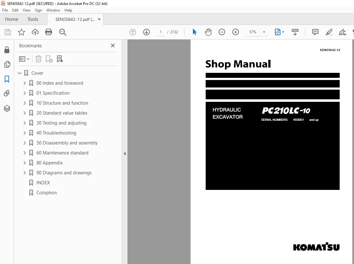
Komatsu Hydraulic Excavator PC210LC-10 Shop Manual SEN05842-12 PDF
$36.95
Komatsu Hydraulic Excavator PC210LC-10 Shop Manual SEN05842-12 – PDF DOWNLOAD
SERIAL NUMBERS 450001 and up
Description
Komatsu Hydraulic Excavator PC210LC-10 Shop Manual SEN05842-12 – PDF DOWNLOAD
FILE DETAILS:
Komatsu Hydraulic Excavator PC210LC-10 Shop Manual SEN05842-12 – PDF DOWNLOAD
Language : English
Pages :2132
Downloadable : Yes
File Type : PDF
IMAGES PREVIEW OF THE MANUAL:
DESCRIPTION:
Komatsu Hydraulic Excavator PC210LC-10 Shop Manual SEN05842-12 – PDF DOWNLOAD
SERIAL NUMBERS 450001 and up
General precautions
Inappropriate handling causes an extreme danger. Read and understand what is described in the operation and maintenance manual before operating the machine. Read and understand what is described in this manual before starting the work.
- Before performing any greasing or repairs, read all the safety labels stuck to the machine. For the locations of the safety labels and detailed explanation of precautions, see the operation and maintenance manual.
- Locate a place in the repair workshop to keep the tools and removed parts. Always keep the tools and parts in their correct places. Always keep the work area clean and make sure that there is no dirt, water or oil on the floor. Smoke only in the areas provided for smoking. Never smoke while working.
- When performing any work, always wear the safety shoes and helmet. Do not wear loose work cloths, or clothes with buttons missing. 1. Always wear the protective eyeglasses when hitting parts with a hammer. 2. Always wear the protective eyeglasses when grinding parts with a grinder, etc.
- When performing any work with 2 or more workers, always agree on the working procedure before starting. While working, always keep conversations of the work between your fellow workers and your self on any step of the work. During the work, hang the warning tag of “UNDER WORKING” in the operator’s compartment.
- Only qualified workers must perform the work and operation which require license or qualification.
- Keep the tools in good condition. And learn the correct way to use the tools, and use the proper ones among them. Before starting the work, thoroughly check the tools, lift truck, service vehicle, etc.
- If welding repairs is required, always have a trained and experienced welder with good knowledge of welding perform the work. When performing welding work, always wear welding gloves, apron, shielding goggles, cap, etc.
- Before starting work, warm up your body thoroughly to start work under good condition.
- Avoid continuing work for long hours and take rests with proper intervals to keep your body in good condition. Take a rest in a specified safe place.
TABLE OF CONTENTS:
Komatsu Hydraulic Excavator PC210LC-10 Shop Manual SEN05842-12 – PDF DOWNLOAD
SERIAL NUMBERS 450001 and up
Cover 1
00 Index and foreword 3
Index 4
Foreword, safety and general information 16
Important safety notice 16
How to read the shop manual 23
Explanation of terms for maintenance standard 25
Handling equipment of fuel system devices 27
Handling of intake system parts 28
Handling of hydraulic equipment 29
Method of disconnecting and connecting of push-pull type coupler 31
Handling of electrical equipment 34
How to read electric wire code 42
Precautions when performing operation 45
Practical use of KOMTRAX 50
Standard tightening torque table 51
List of abbreviation 57
Conversion table 62
01 Specification 67
Table of contents 68
Specifications 69
Specification drawing 69
Working range drawings 70
Specifications 71
Weight table 74
Table of fuel, coolant, and lubricants 75
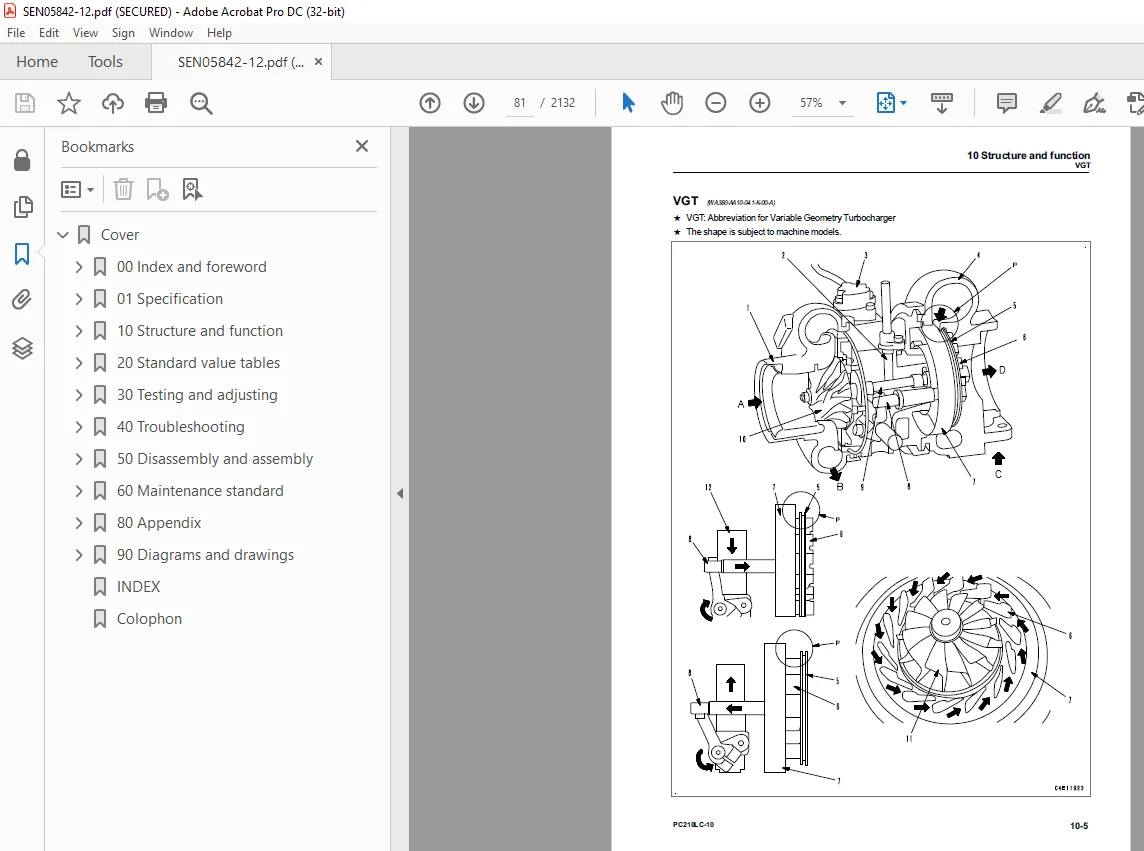
10 Structure and function 77
Table of contents 78
Engine and cooling system 79
Engine related parts 79
VGT 81
EGR system piping drawing 88
EGR system circuit diagram 90
EGR valve 92
EGR cooler 94
KCCV layout drawing 95
KCCV ventilator 97
KDPF 99
Cooling system 103
Power train 105
Power train system 105
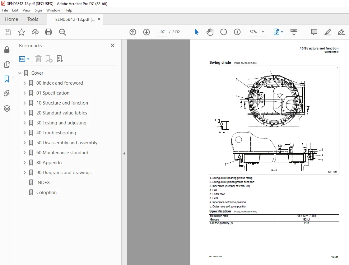
Swing circle 107
Swing machinery 108
Final drive 110
Undercarriage and frame 112
Track frame and idler cushion 112
Hydraulic system 114
Hydraulic equipment layout drawing 114
Valve control 116
Hydraulic tank 118
CLSS 120
Main pump 125
Control valve 150
Swing motor 207
Travel motor 219
PPC valve 232
Solenoid valve 254
Attachment circuit selector valve (for high pressure circuit) 257
Attachment circuit selector valve (for low pressure circuit) 259
Anti-drop valve for boom 262
Anti-drop valve for arm 267
Center swivel joint 272
Accumulator 274
Work equipment 275
Work equipment 275
Work equipment shim 276
Bucket play adjustment shim 277
Cab and its attachments 278
Cab mount and cab tipping stopper 278
ROPS cab 279
Electrical system 280
Electrical control system 280
Machine monitor system 331
KOMTRAX system 353
Sensor 356
20 Standard value tables 377
Table of contents 378
Standard service value table 379
Standard value table for engine 379
Standard value table for machine 381
Standard value table for electrical system 394
30 Testing and adjusting 405
Table of contents 406
Related information on testing and adjusting 407
Tools for testing and adjusting 407
Sketch of tools for testing and adjusting 411
Engine and cooling system 412
Testing engine speed 412
Testing boost pressure 413
Testing exhaust gas color 415
Testing mass air flow and temperature sensor 418
Testing and adjusting valve clearance 421
Testing compression pressure 424
Testing blowby pressure 428
Testing engine oil pressure 429
Testing EGR valve and VGT oil pressures 430
Measuring fuel pressure 431
Measuring fuel delivery, return and leakage 437
Bleeding air from fuel system 442
Testing fuel circuit for leakage 444
Handling cylinder cutout mode operation 445
Handling no-injection cranking operation 446
Testing and adjusting air conditioner compressor belt tension 447
Replacing fan belt 449
Power train 450
Testing swing circle bearing clearance 450
Undercarriage and frame 451
Testing and adjusting track tension 451
Hydraulic system 452
Releasing remaining pressure from hydraulic circuit 452
Testing and adjusting oil pressure in work equipment, swing, and travel circuits 456
Testing oil pressure of control circuit 460
Testing and adjusting oil pressure in pump PC control circuit 463
Testing and adjusting oil pressure in pump LS control circuit 466
Testing output pressure of solenoid valve 471
Testing PPC valve output pressure 475
Adjusting play of work equipment and swing PPC valves 477
Testing pump swash plate sensor 478
Isolating the parts causing hydraulic drift in work equipment 479
Testing oil leakage 481
Bleeding air from hydraulic circuit 484
Testing and charging accumulator (manufactured by NOK) nitrogen gas pressure for attachment (low pressure side) 486
Testing and charging accumulator nitrogen gas pressure for attachment (high pressure side) 488
Replacing accumulator bladder on high pressure side for accumulator piping 490
Cab and its attachments 496
Testing cab tipping stopper 496
Adjusting mirrors 497
Electrical system 499
Special functions of machine monitor 499
Adjusting rearview camera angle 566
Handling voltage circuit of engine controller 568
Handling battery disconnect switch 569
Testing diodes 570
Pm clinic 571
Pm Clinic service 571
40 Troubleshooting 581
Table of contents 582
Related information on troubleshooting 589
Troubleshooting points 589
Sequence of events in troubleshooting 591
Testing before troubleshooting 593
Inspection procedure before troubleshooting 595
Preparation work for troubleshooting of electrical system 614
Classification and procedure for troubleshooting 618
Symptom and troubleshooting numbers 621
Information in troubleshooting table 628
Diagnostic procedure for wiring harness open curcuit of pressure sensor system 630
Connector/electrical wiring connection table 632
Connector contact identification 652
T-branch box and T-branch adapter table 691
Fuse location table 696
Precautions for KDPF (KCSF and KDOC) Cleaning and Replacement 698
Preparation of dummy temperature sensor (for KDOC and KDPF temperature sensors) 701
Preparation of short circuit electrical connector (for failure codes [CA1883] and [CA3135]) 702
Failure codes table 703
Troubleshooting by failure code (Display of code) 712
Failure code [879AKA] 712
Failure code [879AKB] 713
Failure code [879BKA] 714
Failure code [879BKB] 716
Failure code [879CKA] 718
Failure code [879CKB] 719
Failure code [879DKZ] 720
Failure code [879EMC] 722
Failure code [879FMC] 723
Failure code [879GKX] 724
Failure code [989L00] 726
Failure code [989M00] 727
Failure code [989N00] 728
Failure code [A1U0N3] 729
Failure code [A1U0N4] 731
Failure code [AA10NX] 733
Failure code [AB00KE] 735
Failure code [B@BAZG] 737
Failure code [B@BAZK] 738
Failure code [B@BCNS] 740
Failure code [B@BCZK] 741
Failure code [B@HANS] 743
Failure code [CA115] 744
Failure code [CA122] 745
Failure code [CA123] 747
Failure code [CA131] 749
Failure code [CA132] 751
Failure code [CA144] 753
Failure code [CA145] 755
Failure code [CA153] 757
Failure code [CA154] 759
Failure code [CA187] 761
Failure code [CA221] 763
Failure code [CA222] 765
Failure code [CA227] 767
Failure code [CA234] 768
Failure code [CA238] 769
Failure code [CA239] 770
Failure code [CA271] 771
Failure code [CA272] 773
Failure code [CA295] 775
Failure code [CA322] 776
Failure code [CA323] 778
Failure code [CA324] 780
Failure code [CA325] 782
Failure code [CA331] 784
Failure code [CA332] 786
Failure code [CA343] 788
Failure code [CA351] 789
Failure code [CA352] 790
Failure code [CA356] 792
Failure code [CA357] 794
Failure code [CA386] 796
Failure code [CA428] 797
Failure code [CA429] 799
Failure code [CA435] 801
Failure code [CA441] 803
Failure code [CA442] 805
Failure code [CA449] 806
Failure code [CA451] 807
Failure code [CA452] 809
Failure code [CA488] 811
Failure code [CA515] 812
Failure code [CA516] 814
Failure code [CA553] 816
Failure code [CA555] 818
Failure code [CA556] 819
Failure code [CA559] 820
Failure code [CA595] 822
Failure code [CA687] 823
Failure code [CA689] 825
Failure code [CA691] 828
Failure code [CA692] 830
Failure code [CA697] 832
Failure code [CA698] 833
Failure code [CA731] 834
Failure code [CA778] 836
Failure code [CA1117] 841
Failure code [CA1664] 842
Failure code [CA1691] 845
Failure code [CA1695] 847
Failure code [CA1696] 849
Failure code [CA1843] 851
Failure code [CA1844] 853
Failure code [CA1879] 855
Failure code [CA1881] 857
Failure code [CA1883] 859
Failure code [CA1921] 862
Failure code [CA1922] 865
Failure code [CA1942] 868
Failure code [CA1993] 869
Failure code [CA2185] 871
Failure code [CA2186] 873
Failure code [CA2249] 875
Failure code [CA2271] 876
Failure code [CA2272] 879
Failure code [CA2288] 882
Failure code [CA2311] 883
Failure code [CA2349] 884
Failure code [CA2353] 886
Failure code [CA2357] 888
Failure code [CA2373] 890
Failure code [CA2374] 892
Failure code [CA2375] 894
Failure code [CA2376] 896
Failure code [CA2381] 898
Failure code [CA2382] 900
Failure code [CA2383] 903
Failure code [CA2386] 905
Failure code [CA2387] 907
Failure code [CA2554] 911
Failure code [CA2555] 912
Failure code [CA2556] 914
Failure code [CA2637] 916
Failure code [CA2639] 918
Failure code [CA2961] 920
Failure code [CA2973] 921
Failure code [CA3133] 922
Failure code [CA3134] 924
Failure code [CA3135] 926
Failure code [CA3251] 929
Failure code [CA3253] 933
Failure code [CA3254] 937
Failure code [CA3255] 942
Failure code [CA3256] 947
Failure code [CA3311] 952
Failure code [CA3312] 957
Failure code [CA3313] 962
Failure code [CA3314] 965
Failure code [CA3315] 968
Failure code [CA3316] 972
Failure code [CA3317] 975
Failure code [CA3318] 978
Failure code [CA3319] 982
Failure code [CA3321] 985
Failure code [CA3322] 988
Failure code [CA3419] 992
Failure code [CA3421] 994
Failure code [CA3741] 996
Failure code [D110KB] 997
Failure code [D19JKZ] 999
Failure code [D811MC]1002
Failure code [D862KA]1003
Failure code [D8ALKA]1004
Failure code [D8ALKB]1006
Failure code [D8AQKR]1008
Failure code [DA20MC]1012
Failure code [DA22KK]1013
Failure code [DA25KP]1016
Failure code [DA29KQ]1019
Failure code [DA2LKA]1023
Failure code [DA2LKB]1025
Failure code [DA2QKR]1027
Failure code [DA2RKR]1032
Failure code [DAF0MB]1037
Failure code [DAF0MC]1038
Failure code [DAF8KB]1039
Failure code [DAF9KQ]1042
Failure code [DAFGMC]1043
Failure code [DAFLKA]1044
Failure code [DAFLKB]1046
Failure code [DAFQKR]1048
Failure code [DAZ9KQ]1053
Failure code [DAZQKR]1054
Failure code [DB2QKR]1059
Failure code [DB2RKR]1066
Failure code [DGH2KB]1073
Failure code [DHA4KA]1075
Failure code [DHPAMA]1077
Failure code [DHPBMA]1079
Failure code [DHS3MA]1081
Failure code [DHS4MA]1083
Failure code [DHS8MA]1085
Failure code [DHS9MA]1087
Failure code [DHSAMA]1089
Failure code [DHSBMA]1091
Failure code [DHSCMA]1093
Failure code [DHSDMA]1095
Failure code [DHSFMA]1097
Failure code [DHSGMA]1099
Failure code [DHSHMA]1101
Failure code [DHSJMA]1103
Failure code [DKR0MA]1105
Failure code [DKR1MA]1107
Failure code [DR21KX]1109
Failure code [DR31KX]1112
Failure code [DV20KB]1115
Failure code [DW43KA]1117
Failure code [DW43KB]1119
Failure code [DW45KA]1121
Failure code [DW45KB]1124
Failure code [DW91KA]1127
Failure code [DW91KB]1129
Failure code [DWA2KA]1131
Failure code [DWA2KB]1133
Failure code [DWK0KA]1135
Failure code [DWK0KB]1137
Failure code [DWK2KA]1139
Failure code [DWK2KB]1141
Failure code [DWK8KA]1143
Failure code [DWK8KB]1145
Failure code [DXA8KA]1147
Failure code [DXA8KB]1150
Failure code [DXA9KA]1153
Failure code [DXA9KB]1156
Failure code [DXE0KA]1159
Failure code [DXE0KB]1161
Failure code [DXE4KA]1163
Failure code [DXE4KB]1165
Failure code [DXE5KA]1167
Failure code [DXE5KB]1169
Failure code [DXE6KA]1171
Failure code [DXE6KB]1173
Failure code [DY20KA]1175
Failure code [DY20MA]1177
Failure code [DY2CKB]1179
Failure code [DY2DKB]1182
Failure code [DY2EKB]1184
Troubleshooting of electrical system (E-mode)1186
E-1 Engine does not start (Engine does not crank)1186
E-2 Manual preheating system does not work1192
E-3 Automatic preheating system does not work1195
E-4 While preheating is working, preheating monitor does not light up1198
E-5 When starting switch is turned to ON position, machine monitor displays nothing1200
E-6 While starting switch is turned to ON position (with engine stopped), engine oil level monitor lights up in yellow1203
E-7 While starting switch is turned to on position (with engine stopped), radiator coolant level monitor lights up in yellow1204
E-8 Engine coolant temperature monitor lights up in white while engine is running1205
E-9 Hydraulic oil temperature monitor lights up in white while engine is running1206
E-10 Charge level monitor lights up while engine is running1207
E-11 Fuel level monitor lights up in red while engine is running1208
E-12 Air cleaner clogging monitor lights up in yellow while engine is running1209
E-13 Water separator monitor lights up while engine is running1210
E-14 Engine coolant temperature monitor lights up in red while engine is running1211
E-15 Hydraulic oil temperature monitor lights up in red while engine is running1212
E-16 Fuel gauge display does not move from minimum or maximum1213
E-17 Display of fuel gauge differs from actual fuel level (indicates neither full nor empty)1215
E-18 Engine coolant temperature gauge display does not move from minimum or maximum1216
E-19 Display of engine coolant temperature gauge differs from actual coolant temperature (indicates neither Min nor Max)1217
E-20 Hydraulic oil temperature gauge display does not move from minimum or maximum1218
E-21 Display of hydraulic oil temperature gauge differs from actual oil temperature (indicates neither Min nor Max)1220
E-22 Some areas of machine monitor screen are not displayed1221
E-23 Function switch does not operate1222
E-24 Automatic warm-up system does not work (in cold weather)1223
E-25 When auto-decelerator switch is operated, auto-decelerator monitor does not light up or does not go out1225
E-26 Auto-decelerator is not operated or canceled with lever1226
E-27 When working mode switch is operated, working mode selection screen is not displayed1227
E-28 When working mode is changed, setting of engine and hydraulic pump is not changed1228
E-29 When travel speed switch is operated, travel speed monitor does not change1229
E-30 When travel speed selection is changed, actual travel speed does not change1230
E-31 Alarm buzzer cannot be canceled1232
E-32 Service meter is not displayed, while starting switch is in OFF position1233
E-33 Service mode cannot be selected1234
E-34 All work equipment, swing and travel mechanism do not move1235
E-35 Work equipment, swing, and travel mechanism do not lock1238
E-36 When swing brake cancel switch is set to cancel position, machine cannot swing1240
E-37 When swing brake cancel switch is set to NORMAL position, swing holding brake does not operate1243
E-38 One-touch power maximizing function does not work or monitor is not displayed1245
E-39 One-touch power maximizing function is not cancelled1247
E-40 Travel alarm does not sound during travel1249
E-41 Travel alarm does not stop sounding while machine is stopped1251
E-42 Horn does not sound1252
E-43 Horn does not stop sounding1254
E-44 When wiper switch is operated, wiper monitor does not light up or go out1256
E-45 When wiper switch is operated, windshield wiper does not operate1257
E-46 When window washer switch is operated, window washer does not operate1259
E-47 Boom RAISE indication is not displayed properly with monitoring function1260
E-48 Boom LOWER indication is not displayed properly with monitoring function1261
E-49 Arm OUT indication is not displayed properly with monitoring function1262
E-50 Arm IN indication is not displayed properly with monitoring function1263
E-51 Bucket CURL indication is not displayed properly with monitoring function1264
E-52 Bucket DUMP indication is not displayed properly with monitoring function1265
E-53 SWING indication is not displayed properly with monitoring function1266
E-54 TRAVEL indication is not displayed properly with monitoring function1267
E-55 Service indicator is not displayed properly with monitoring function when service pedal is operated1268
E-56 Service indicator is not displayed properly with monitoring function when starting switch is turned to ON position1270
E-57 Attachment hydraulic circuit cannot be changed1272
E-58 KOMTRAX system does not operate normally1274
Troubleshooting of hydraulic and mechanical system (H-mode)1276
Information described in troubleshooting table (H-mode)1276
System chart for hydraulic system1278
Failure mode and cause table1280
H-1 All work equipment, swing and travel lack speed and power1288
H-2 Engine speed drops significantly or engine stalls1292
H-3 All work equipment, swing, and travel mechanism do not move1295
H-4 Unusual noise is heard from around hydraulic pump1296
H-5 Fine control performance or response is poor1298
H-6 Boom speed or power is low1300
H-7 Arm speed or power is low1305
H-8 Bucket speed or power is low1310
H-9 Work equipment does not move in single operation1314
H-10 Hydraulic drift of boom is large1316
H-11 Hydraulic drift of arm is large1317
H-12 Hydraulic drift of bucket is large1319
H-13 Time lag of work equipment is large1321
H-14 When single work equipment is relieved hydraulically, other work equipment moves1324
H-15 One-touch power maximizing function does not operate1326
H-16 In combined operation of work equipment, equipment having heavier load moves slower1327
H-17 In combined operations of swing and boom RAISE, boom rising speed is low1329
H-18 In combined operation of swing and travel, travel speed drops largely1330
H-19 Machine does not travel straight1331
H-20 Travel speed is slow1336
H-21 Machine is not steered well or steering power is low1340
H-22 Travel speed does not change, or travel speed is too slow or fast1347
H-23 One of tracks does not run1349
H-24 Upper structure does not swing both to the right and left1353
H-25 Upper structure swings only in one direction1355
H-26 Swing acceleration or swing speed is low in both directions (right and left)1357
H-27 Swing acceleration performance is poor or swing speed is slow in only one direction1360
H-28 Upper structure overruns excessively when it stops swinging (both right and left)1362
H-29 Upper structure overruns excessively when it stops swinging (only one direction either right or left)1363
H-30 Shock is large when upper structure stops swinging1365
H-31 Large unusual noise is heard when upper structure stops swinging1366
H-32 Swing drift on a slope is large while swing parking brake is applied1368
H-33 Swing drift on a slope is large while swing parking brake is released1369
H-34 Attachment hydraulic circuit cannot be changed while attachment is installed1372
H-35 Oil flow in attachment circuit cannot be changed1373
Troubleshooting of engine (S-mode)1374
Information mentioned in troubleshooting table (S mode)1374
S-1 When starting switch is turned to START position, engine does not crank1375
S-2 Engine cranks but no exhaust smoke comes out1376
S-3 Fuel is being injected but engine does not start (misfiring: engine cranks but does not start)1378
S-4 Engine startability is poor1381
S-5 Engine does not pick up smoothly1384
S-6 Engine stops during operation1387
S-7 Engine runs rough or is unstable1391
S-8 Engine lacks power1393
S-9 Exhaust smoke from engine outlet (in front of KDPF) is black (KDPF gets clogged in a short time)1397
S-10 Engine oil consumption is excessive1400
S-11 Engine oil becomes contaminated early1403
S-12 Fuel consumption is excessive1405
S-13 Oil is in coolant (or coolant spurts or coolant level goes down)1407
S-14 Engine oil pressure drops1408
S-15 Fuel is contaminated in engine oil1412
S-16 Coolant is contaminated in engine oil (Oil becomes cloudy white)1413
S-17 Coolant temperature rises too high (overheating)1415
S-18 Unusual noise is heard1417
S-19 Vibration is excessive1419
S-20 Air cannot be bled from fuel circuit1421
S-21 Active regeneration is executed frequently1422
S-22 Active regeneration takes time1424
S-23 White smoke is exhausted during active regeneration1426
50 Disassembly and assembly1427
Table of contents1428
Related information on disassembly and assembly1430
How to read this manual1430
Coating materials list1432
Special tools list1436
Sketches of special tools1441
Engine and cooling system1445
Removing and installing the supply pump assembly1445
Removing and installing the injector assembly1452
Removing and installing the cylinder head assembly1464
Removing and installing the radiator assembly1494
Removing and installing the hydraulic oil cooler assembly1499
Removing and installing the aftercooler assembly1506
Removing and installing the engine and main pump assembly1510
Removing and installing the engine front seal1538
Removing and installing the engine rear seal1546
Removing and installing the fuel cooler assembly1550
Removing and installing the fuel tank assembly1553
Removing and installing the engine hood assembly1563
Removing and installing KDPF assembly1570
Disassembling and assembling KDPF assembly1582
Removing and installing KCCV assembly1593
Removing and installing the air cleaner assembly1600
Power train1605
Removing and installing the travel motor and final drive assembly1605
Disassembling and assembling the final drive assembly1610
Removing and installing the swing motor and swing machinery assembly1624
Disassembling and assembling the swing machinery assembly1635
Removing and installing the swing circle assembly1646
Undercarriage and frame1648
Separating and connecting the track shoe assembly1648
Removing and installing the sprocket1653
Removing and installing the idler and idler cushion assembly1655
Disassembling and assembling the idler cushion assembly1662
Disassembling and assembling the track roller assembly1665
Disassembling and assembling the carrier roller assembly1668
Removing and installing the revolving frame assembly1672
Removing and installing the counterweight assembly1678
Hydraulic system1685
Removing and installing the center swivel joint assembly1685
Disassembling and assembling the center swivel joint assembly1691
Removing and installing the hydraulic tank assembly1694
Removing and installing the main pump assembly1705
Removing and installing the control valve assembly1715
Disassembling and assembling the control valve assembly1737
Disassembling and assembling the work equipment PPC valve assembly1744
Disassembling and assembling the travel PPC valve assembly1747
Removing and installing the work equipment assembly1750
Removing and installing the boom anti-drop valve assembly1761
Removing and installing the arm anti-drop valve assembly1764
Disassembling and assembling the anti-drop valve assembly1767
Disassembling and assembling of the work equipment cylinder assembly1768
Cab and its attachments1777
Removing and installing the operator’s cab assembly1777
Removing and installing the operator’s cab glass (adhered glass)1793
Removing and installing the front window assembly1806
Removing and installing the floor frame assembly1817
Removing and installing the air conditioner unit assembly1836
Removing and installing the operator’s seat1847
Removing and installing the seat belt1851
REMOVE AND INSTALL WORK EQUIPMENT CONTROL LEVER ASSEMBLY1853
Removing and installing the front wiper assembly1867
Electric system1882
Removing and installing the air conditioner compressor assembly1882
Removing and installing the air conditioner condenser assembly1886
Removing and installing the engine controller assembly1888
Removing and installing the pump controller assembly1891
Removing and installing the machine monitor assembly1897
Removing and installing the pump swash plate sensor1903
Removing and installing the mass air flow and temperature sensor1905
Removing and installing KOMTRAX terminal assembly1907
60 Maintenance standard1913
Table of contents1914
Engine and cooling system1915
Engine mount1915
Cooling system1916
Power train1917
Swing circle1917
Swing machinery1918
Final drive1920
Sprocket1922
Undercarriage and frame1924
Track frame and idler cushion1924
Idler1926
Track roller1928
Carrier roller1929
Track shoe1930
Hydraulic system1936
Hydraulic tank1936
Main pump1937
Control valve1938
Anti-drop valve for boom1948
Anti-drop valve for arm1950
Swing motor1952
Travel motor1954
Work equipment and swing PPC valve1957
Travel PPC valve1960
1st-line attachment PPC valve (with EPC valve)1962
2nd-line attachment PPC valve1965
Solenoid valve1967
Attachment circuit selector valve (for high-pressure circuit)1968
Attachment circuit selector valve (for low-pressure circuit)1969
Center swivel joint1970
Work equipment1971
Work equipment1971
Boom cylinder (large diameter piston)1980
Arm cylinder1981
Bucket cylinder1982
80 Appendix1983
Table of contents1984
Air conditioner components1985
Precautions for refrigerant1985
Air conditioner component1986
Configuration and function of refrigeration cycle1989
Outline of refrigeration cycle1990
Air conditioner unit1992
Dual pressure switch1999
Air conditioner controller2000
Compressor2001
Air conditioner condenser2002
Sunlight sensor2004
Outer temperature sensor (outside air temperature sensor)2005
Procedure for testing and troubleshooting2006
Circuit diagram and arrangement of connector pins2008
System diagram2010
Input and output signals of the air conditioner controller2011
Parts and connectors layout2013
Testing air leakage (duct)2017
Testing with self-diagnosis function2020
Testing vent (mode) changeover2023
Testing FRESH/RECIRC air changeover2025
Testing sunlight sensor2026
Testing (dual) pressure switch for refrigerant2027
Testing relays2028
Troubleshooting chart 12029
Troubleshooting chart 22030
Information in troubleshooting table2033
Failure code list related to air conditioner2034
Failure code [879AKA] A/C Inner Sensor Open Circuit2035
Failure code [879AKB] A/C Inner Sensor Short Circuit2036
Failure code [879BKA] A/C Outer sensor Open Circuit2037
Failure code [879BKB] A/C Outer sensor Short Circuit2039
Failure code [879CKA] Ventilating Sensor Open Circuit2041
Failure code [879CKB] Ventilating Sensor Short Circuit2042
Failure code [879DKZ] Sunlight sensor Open or Short Circuit2043
Failure code [879EMC] Ventilation Damper Abnormality2045
Failure code [879FMC] Air Mix Damper Abnormality2046
Failure code [879GKX] Refrigerant Abnormality2047
A-1 Troubleshooting for power supply system (Air conditioner does not operate)2048
A-2 Troubleshooting of compressor system (Air is not cooled)2050
A-3 Troubleshooting for blower motor system (No air comes out or air flow is abnormal)2053
A-4 Troubleshooting for FRESH/RECIRC air changeover2055
Troubleshooting with gauge pressure2057
Connection of service tool2060
Precautions for disconnecting and connecting air conditioner piping2062
Handling of compressor oil2064
Desiccant replacement2066
90 Diagrams and drawings2069
Table of contents2070
Hydraulic circuit diagram2071
Symbols in hydraulic circuit diagram2071
Hydraulic circuit diagram2075
Electric circuit diagram2083
Symbols in electric circuit diagram2083
Electrical circuit diagram2087
Electrical circuit diagram for air conditioner unit2099
Wiring harness diagram2101
INDEX2123
Colophon2132
S.M 29/12/24