Komatsu HYDRAULIC EXCAVATOR PC210LCE-1 1 Electric Shop Manual SEN06970-02 PDF
$34.95
Komatsu HYDRAULIC EXCAVATOR PC210LCE-1 1 Electric Shop Manual SEN06970-02 – PDF DOWNLOAD
SERIAL NUMBERS 80001 and up
Description
Komatsu HYDRAULIC EXCAVATOR PC210LCE-1 1 Electric Shop Manual SEN06970-02 – PDF DOWNLOAD
FILE DETAILS:
Komatsu HYDRAULIC EXCAVATOR PC210LCE-1 1 Electric Shop Manual SEN06970-02 – PDF DOWNLOAD
Language : English
Pages :1344
Downloadable : Yes
File Type : PDF
DESCRIPTION:
Komatsu HYDRAULIC EXCAVATOR PC210LCE-1 1 Electric Shop Manual SEN06970-02 – PDF DOWNLOAD
SERIAL NUMBERS 80001 and up
How to Read the Shop Manual
• Some of the attachments and options described in this shop manual may not be available in some areas. If
they are required, consult your Komatsu distributor.
• The materials and specifications are subject to change without notice.
• Shop Manuals are available for “machine part” and “engine part”. For the engine unit, see the shop manual
for the machine which has the same engine model.
• Actual machine may differ from the images which are contained in this manual. A typical model is shown in
the illustrations of this shop manual.
• The caution lamps, pilot lamps, and symbols of the switches on the machine monitor can be different in
accordance with the machine.
• For details of the symbols shown on the machine monitor, see Structure and Operation, “Caution
Lamps Shown on Machine Monitor” and “Pilot Lamps Shown on Machine Monitor”.
• For details of the switches of the machine monitor, see Testing and Adjusting, “Set and Operate Machine
Monitor”.
• For details of the switches, see the “Operation and Maintenance Manual”.
• All “AdBlue/DEF” shown on the machine monitor is referred to as “DEF” in the shop manual. Some machine
monitors installed to the product show “DEF” as “AdBlue/DEF” in the service mode. Thus, be sure to recognize
that “DEF” and “AdBlue/DEF” are the same when you read the shop manual.
REMARK
The illustrations in the shop manual reproduce the display of the machine monitor. They are not always the
same as the terminology in the shop manual.
Composition of the Shop Manual
This shop manual contains technical information necessary to perform services in workshops. It is divided into
the following chapters for the ease of use.
00 Index and Foreword
This section describes the index, foreword, safety, and basic information.
01 Specification
This section describes the specifications of the machine.
10 Structure and Function
This section describes the structure and operation of each component with respect to each system. “Structure
and Function” is helpful in not only understanding the structure of each component but performing troubleshooting.
20 Standard Value Table
This section describes the standard values for new machine and failure criteria for testing and adjusting, and
troubleshooting. Use the standard values table to check the standard values for testing and adjusting, and judge
troubles in troubleshooting.
30 Testing and Adjusting
This section describes the measuring tools and measuring methods for testing and adjusting as well as the adjusting
method of each part. The standard values and repair limit for TESTING AND ADJUSTING are described
in “Standard Value Table”.
40 Troubleshooting
This section describes troubleshooting of failure part and its remedy method on the occurrence of the failure.
Descriptions of troubleshooting are sorted by failure mode.
This section describes the special tools, work procedures, and safety precautions necessary for removal, installation,
disassembly, and assembly of the components and parts. In addition, tightening torques, quantity, and
weight of the coating materials, lubricants, and coolant necessary to these works are shown.
60 Maintenance Standard
This section describes the maintenance standard value of each component. The maintenance standard shows
the criteria and remedies for disassembly and assembly.
80 Others
This section describes the structure and function, testing and adjusting, and troubleshooting for all of the other
components or equipment which cannot be separately classified in the appendix.
90 Circuit Diagrams
This section describes hydraulic circuit diagrams and electrical circuit diagrams.
TABLE OF CONTENTS:
Komatsu HYDRAULIC EXCAVATOR PC210LCE-1 1 Electric Shop Manual SEN06970-02 – PDF DOWNLOAD
SERIAL NUMBERS 80001 and up
Cover 1
00 Index and Foreword 3
Index 4
Abbreviation List 10
Foreword, Safety, Basic Information 13
How to Read the Shop Manual 13
Safety Notice for Operation 15
Precautions for Battery-Powered Hydraulic Excavator 23
Precautions to Prevent Fire 24
Procedures If Fire Occurs 24
Prevent Fire 24
Precautions When You Discard Waste Materials 28
Precautions When You Handle Hydraulic Equipment 29
Precautions When You Disconnect and Connect Pipings 32
Precautions When You Handle Electrical Equipment 38
Precautions for Maintenance of Power Electronics Components 40
Handle Power Electronics Components 41
Precautions for Normal Inspection and Maintenance 42
Precautions When Machine Falls over and Power Electronics Components Have Damage 43
Precautions for Machine Not to be Put in Water 44
Related Regulations 45
Practical Use of KOMTRAX 46
Disconnect and Connect Push-Pull Type Coupler 47
How to Disconnect and Connect Type 1 Push-Pull Type Coupler 47
How to Disconnect and Connect Type 2 Push-Pull Type Coupler 48
How to Disconnect and Connect Type 3 Push-Pull Type Coupler 49
Precautions for Disconnection and Connection of Connectors 51
How to Disconnect and Connect Deutsch Connector 55
How to Disconnect and Connect Slide Lock Type Connector 56
How to Disconnect and Connect Connector with Lock to Pull 58
How to Disconnect and Connect Connector with Lock to Push 59
How to Disconnect and Connect Connector with Housing to Rotate 61
How to Read the Codes for Electric Cable 62
Explanation of Terms for Maintenance Standard 66
Standard Tightening Torque Table 69
Conversion Table 76
01 Specifications 81
Table of Contents 82
Specifications 83
Specification Drawing 83
Specification Drawing: PC210LCE-11 83
Working Range Drawings 84
Working Range Drawings: PC210LCE-11 84
Specifications 85
Specifications: PC210LCE-11 85
Weight Table 88
Weight Table: PC210LCE-11 88
Coolant, Lubricant 90
How to Use Coolant and Lubricants by Ambient Temperature 90
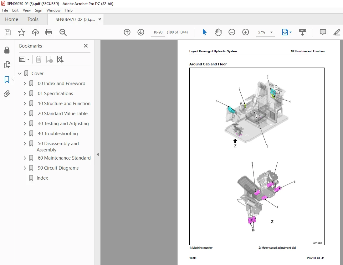
10 Structure and Function 93
Table of Contents 94
Boot-up System 98
Layout Drawing of Boot-up System 98
System Operating Lamp System 99
System Diagram of System Operating Lamp System 99
Function of Operation Lamp System 99
Operation of System Operating Lamp System 99
Auxiliary Battery Disconnect Switch 100
Function of Auxiliary Battery Disconnect Switch 100
Function of Electric Motor Shutdown Secondary Switch 101
Function of Electric Motor Shutdown Secondary Switch 101
Operation of Electric Motor Shutdown Secondary Switch 101
Electric Drive System 102
Layout Drawing of Electric Drive System 102
System Diagram of Electric Drive System 103
Structure of Electric Drive System 104
Worker Protection System When You Disassemble Power Electronics Components 105
Function of Worker Protection System When You Disassemble Power Electronics Components 105
High Voltage Wiring (Power Cable) 106
Layout Drawing of High Voltage Wiring (Power Cable) 106
Structure of High Voltage Wiring (Power Cable) 106
Function of High Voltage Wiring (Power Cable) 106
Component Parts of Electric Drive System 107
Main Battery Assembly 107
BTMS (Battery Thermal Management System) 109
Inverter 111
DC-DC Converter 113
HVJB (High Voltage Junction Box) 114
Power Distribution Unit 116
Electric Motor 119
Charging Port 121
Electric Motor System 123
Layout Drawing of Electric Motor System 123
Electric Motor Control System 124
System Diagram of Electric Motor Control System 124
Operation of Electric Motor Control System 124
Auto-Deceleration System 126
System Diagram of Auto-Deceleration System 126
Function of Auto-Deceleration System 126
Operation of Auto-Deceleration System 127
Overheat Prevention System 128
Overheat Prevention System Diagram 128
Function of Overheat Prevention System 129
Component Parts of Electric Motor System 131
Coupling 131
Cooling System 132
Layout Drawing of Cooling System 132
Specifications of Cooling System 134
Fan Speed Control System of Electric Fan 135
Function of Fan Speed Control System of Electric Fan 135
Component Parts of Cooling System 136
Electric Fan 136
Control System 137
Layout Drawing of Control System 137
Machine Monitor System 138
System Diagram of Machine Monitor System 138
Function of Machine Monitor System 139
KomVision System 140
Layout Drawing of KomVision System 140
System Diagram of KomVision System 142
Function of KomVision System 142
KOMTRAX System 144
System Diagram of KOMTRAX System 144
Function of KOMTRAX System 144
Component Parts of Control System 145
Machine Monitor 145
KomVision Controller 160
KomVision Camera 164
Gateway Function Controller 165
Communication Terminal 168
Pump Controller 169
Resistor for PC-EPC Valve 173
CAN Terminating Resistor 173
Power Management Controller 174
Battery Integration Controller 178
Telemetry (Battery Information Communication Terminal) 182
Electric Fan Controller 183
Motor Speed Adjustment Dial 185
Quick Coupler Low Pressure Alarm Switch 187
Hydraulic System 188
Layout Drawing of Hydraulic System 188
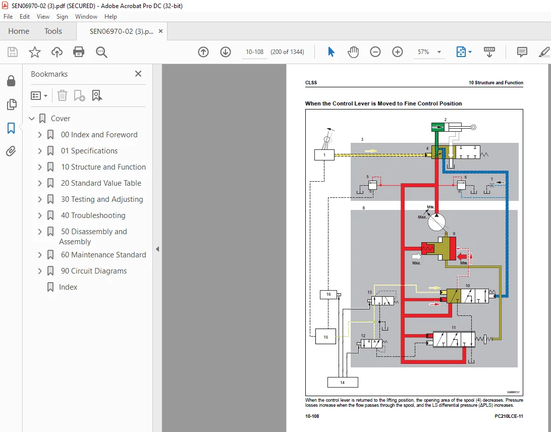
CLSS 192
Structure of CLSS 192
Operation of Unload Valve and LS Pressure 194
Pump Swash Plate Angle (Oil Flow) Control 195
Pressure Compensation Control 211
Electric Motor and Pump Combined Control System 214
System Diagram of Electric Motor and Pump Combined Control System 214
Function of Electric Motor and Pump Combined Control System 215
Pump and Valve Control System 220
Pump and Valve Control System Diagram 220
Function of Pump and Valve Control System 221
Component Parts of Hydraulic System 223
Hydraulic Tank 223
Main Pump 225
Control Valve 251
Work Equipment System 311
Layout Drawing of Work Equipment System 311
Structure of Valve Control 316
One-Touch Power Maximizing System 318
System Diagram of One-Touch Power Maximizing System 318
Function of One-Touch Power Maximizing System 319
PPC Lock System 320
System Diagram of PPC Lock 320
Function of PPC Lock System 320
Work Equipment and Travel Automatic Lock System 321
System Diagram of Lock Lever Automatic Lock System 321
Function of Work Equipment and Travel Automatic Lock System 321
Operation of Lock Lever Automatic Lock System 322
Attachment Oil Flow Adjuster System 323
Attachment Oil Flow Adjuster System Diagram 323
Function of Attachment Oil Flow Adjuster System 324
Bucket DUMP Control Lock System 325
Bucket DUMP Control Lock System Diagram 325
Function of Bucket DUMP Control Lock System 325
Tool Control System 326
Tool Control System Diagram 326
Component Parts of Work Equipment System 328
Work Equipment and Swing PPC Valve 328
1st-Line Attachment PPC Valve (with EPC Valve) 335
2nd-Line Attachment PPC Valve 343
Solenoid Valve 345
Bucket DUMP Control Lock Solenoid Valve 349
Boom Anti-drop Valve 351
Arm Anti-Drop Valve 356
Attachment Circuit Selector Valve (For High Pressure) 361
Attachment Circuit Selector Valve (For Low Pressure) 363
1st-Line Attachment Variable Relief Valve 365
Attachment Bypass Solenoid Valve 368
Pilot Circuit Accumulator 370
Attachment Circuit Accumulator 371
Swing System 372
Layout Drawing of Swing System 372
Swing Control System Diagram 376
Function of Swing Control System 376
Component Parts of Swing System 380
Swing Motor 380
Swing Machinery 392
Swing Circle 394
Travel System 395
Layout Drawing of Travel System 395
System Diagram of Travel Control System 399
Function of Travel Control System 399
Component Parts of Travel System 401
Travel Motor 401
Final Drive 415
Travel PPC Valve 417
Center Swivel Joint 421
Undercarriage and Frame 423
Layout Drawing of Undercarriage 423
Specifications of Undercarriage 424
Work Equipment 425
Structure of Work Equipment 425
Function of Work Equipment 425
Work Equipment Clearance Adjustment Shim 426
Function of Work Equipment Clearance Adjustment Shim 426
Bucket Clearance Adjustment Shim 426
Function of Bucket Clearance Adjustment Shim 426
CAB Related Parts 427
ROPS CAB 427
Structure of ROPS CAB 427
Function of ROPS CAB 427
CAB Mount 428
Structure of CAB Mount 428
Function of CAB Mount 428
CAB Tipping Stopper 429
Structure of CAB Tipping Stopper 429
Function of CAB Tipping Stopper 429
Quick Coupler System 430
Structure of Hydraulic Slider Type Quick Coupler Assembly 430
Operation of Hydraulic Slider Type Quick Coupler Assembly (Unlock) 432
Operation of Hydraulic Slider Type Quick Coupler Assembly (Lock) 432
Structure of Hydraulic Full-Automatic Type Quick Coupler 433
Operation of Hydraulic Full-Automatic Type Quick Coupler (Unlock) 434
Operation of Hydraulic Full-Automatic Type Quick Coupler (Lock) 434
20 Standard Value Table 435
Table of Contents 436
Standard Value Table for Electric Motor 437
Standard Value Table for Electric Motor: PC210LCE-11 437
Standard Value Table for Machine 438
Standard Value Table for Machine: PC210LCE-11 438
Machine Posture and Procedures to Measure Performance 449
30 Testing and Adjusting 453
Table of Contents 454
Precautions Before Work 457
Related Information on Testing and Adjusting 458
Tools for Testing and Adjusting 458
Sketch of Tools for Testing and Adjusting 464
Motor and Cooling System 465
Examine Electric Motor Speed 465
How to Examine Electric Motor High Idle Speed 465
How to Examine Electric Motor Low Idle Speed 465
How to Examine Electric Motor Speed at 2 Pump Relief 465
How to Examine Electric Motor Speed at 2 Pump Relief and One-Touch Power Maximizing 466
How to Examine Electric Motor Speed with Auto-Deceleration 466
Examine Air Conditioner Compressor Belt Tension 468
How to Examine Air Conditioner Compressor Belt 468
Examine Automatic Tensioner 469
How to Examine Automatic Tensioner 469
Electric Drive System 470
Precautions for Electric Drive System 470
Examine Tightening Torque of Electric Motor High Voltage Wiring Terminal 471
How to Examine Tightening Torque of Electric Motor High Voltage Wiring Terminal 471
Replace Desiccant for Main Battery 473
How to Replace Desiccant for Main Battery 473
Examine Water Level of Hot Water Heater and Add Water 476
How to Examine Water Level of Hot Water Heater and Add Water 476
Power Train 477
Examine Swing Circle Bearing Clearance 477
How to Examine Swing Circle Bearing Clearance 477
Undercarriage and Frame 478
Examine and Adjust Track Tension 478
How to Examine Track Tension 478
How to Adjust Track Tension 478
Hydraulic System 480
Release Remained Pressure in Hydraulic Circuit 480
How to Release Remained Pressure from Hydraulic Tank 480
How to Release Remained Pressure in Hydraulic Cylinder Circuit 480
How to Release Remained Pressure from Swing Motor Circuit 485
How to Release Remained Pressure from Travel Motor Circuit 485
Examine and Adjust Oil Pressure in Work Equipment, Swing, and Travel Circuits 487
How to Examine Oil Pressure in Work Equipment, Swing, and Travel Circuits 488
How to Adjust Oil Pressure in Work Equipment, Swing, and Travel Circuits 494
Examine Oil Pressure of Control Circuit 497
How to Examine Oil Pressure in Control Circuit 497
Examine and Adjust Oil Pressure in Pump PC Control Circuit 499
Examine PC Valve Outlet Pressure (Servo Piston Inlet Pressure) 499
Examine PC-EPC Valve Outlet Pressure 500
How to Adjust Oil Pressure in Pump PC Control Circuit 501
Examine and Adjust Oil Pressure in Pump LS Control Circuit 503
Examine LS Differential Pressure with Machine Monitor 503
How to Examine LS Differential Pressure by Testing Tool 504
How to Examine LS Valve Outlet Pressure (Servo Piston Inlet Pressure) 507
How to Examine LS-EPC Valve Outlet Pressure 508
How to Adjust LS Valve 509
Examine Outlet Pressure of Solenoid Valve 510
How to Examine Outlet Pressure of Solenoid Valve 510
Operating Condition of Solenoid Valve 511
Examine PPC Valve Outlet Pressure 514
How to Examine PPC Valve Outlet Pressure 514
Examine Attachment Circuit Oil Pressure 516
How to Examine Attachment Circuit Oil Pressure 516
Adjust Play of Work Equipment and Swing PPC Valves 517
How to Adjust Play of Work Equipment and Swing PPC Valves 517
Examine Pump Swash Plate Sensor 518
How to Examine Pump Swash Plate Sensor 518
Examine Parts Which Cause Hydraulic Drift of Work Equipment 519
How to Examine Parts Which Cause Hydraulic Drift of Boom Cylinder and Bucket Cylinder 519
How to Examine the Parts Which Cause Hydraulic Drift of Arm Cylinder 519
How to Examine Parts that Cause Hydraulic Drift of PPC Valve 520
Examine Oil Leakage 521
How to Examine Oil Leakage from Boom Cylinder 521
How to Examine Oil Leakage from Arm Cylinder 521
How to Examine Oil Leakage from Bucket Cylinder 522
How to Examine Oil Leakage from Swing Motor 523
How to Examine Oil Leakage from Travel Motor 523
Bleed Air from Hydraulic System 525
How to Bleed Air from Hydraulic System 526
Examine Oil Pressure of Pressure Reducing Valve 528
How to Examine Pressure Reducing Valve Oil Pressure 529
Examine and Charge Accumulator (Made by NOK) Nitrogen Gas Pressure for Attachment (Low Pressure Side) 532
How to Examine Accumulator (Made by NOK) Nitrogen Gas Pressure for Attachment (Low Pressure Side) 532
Examine and Charge Accumulator Nitrogen Gas Pressure for Attachment (High Pressure Side) 536
How to Examine Accumulator Nitrogen Gas Pressure for Attachment (High Pressure Side) 536
Replace Accumulator Bladder on High Pressure Side for Attachment Piping 540
How to Replace Accumulator Bladder on High Pressure Side for Attachment Piping 540
Work Equipment 547
Examine Oil Pressure Auto Coupler 547
Examine Guide Plate for Damage 547
Examine Clearance Between Locking Pin and Bushing 547
How to Examine Lubrication and Antirust Application in Housing 547
Examine Tightness of Linkage 548
Replace S-Block Valve 550
How to Replace S-Block Valve 550
How to Replace S-Block Valve O-Ring (Outer) 551
How to Replace S-Block Valve O-Ring (Contact Surface) 552
Replace A-Block Valve 554
How to Replace A-Block Valve 554
How to Replace A-Block Valve O-Ring (Outer) 555
How to Replace A-Block Valve O-Ring (Inner) 555
Replace Buffer Element and Socket 558
How to Replace Buffer Element and Socket 558
CAB Related Parts 560
Examine CAB Tipping Stopper 560
How to Examine Cab Tipping Stopper 560
How to Adjust Mirrors 561
Procedure to Adjust Left Front Mirror (A) 562
Procedure to Adjust Regular Position of Machine Left Front Mirror (A) 563
Procedure to Adjust Right Front Mirror (B) 565
Procedure to Adjust Regular Position of Machine Right Front Mirror (B) 565
Procedure to Adjust Right Front Mirror (C) 568
Electrical System 569
Set and Operate Machine Monitor 569
Operator Mode 573
Function to Show Technician Identification Status Screen 573
Function to Show Operator Identification Input Screen 573
Examine Function by LCD (Liquid Crystal Display) 574
Examine Function of Service Meter 574
Usage Limitation and Maintenance Password Change Function 574
Service Mode 577
How to Operate Service Mode 577
How to See Pre-defined Monitoring Information 579
How to Examine Monitoring Information 584
Abnormality Record Menu 595
How to See Maintenance Record 599
Maintenance Mode Setting 600
How to Set Phone Number Entry 604
Default Setting Menu 606
Testing Menu 618
Adjustment Menu 619
KOMTRAX Settings Menu 650
How to Show Service Message 652
Start Up KOMTRAX System 654
Stop Use of KOMTRAX System 660
Adjust KomVision Camera Angle 662
How to Adjust KomVision Camera Angle 663
Adjust KomVision Related Function 666
Setting of KomVision (Main Setting) 667
Setting of KomVision (Camera Setting) 669
Setting of KomVision (Camera Calibration) 671
KomVision Screen – 12m Visibility Check 684
Set Region of Bluetooth(R) Compatible Radio 687
How to Set Region of Bluetooth(R) Compatible Radio 687
Handle MSD of High Voltage Junction Box 689
Handle MSD of Main Battery 690
Handle Voltage Circuit of Power Management Controller 691
Handle Auxiliary Battery Disconnect Switch 692
Examine Diodes 693
How to Examine Diodes by Digital Tester 693
How to Examine Diodes by Analog Tester 693
Pm Clinic 694
Pm Clinic Service 694
Pm Clinic Check Sheet: PC210LCE-11 696
40 Troubleshooting 705
Table of Contents 706
Precautions Before Work 707
Related Information to Troubleshooting 708
Failure Code Table 708
50 Disassembly and Assembly 737
Table of Contents 738
Precautions Before Work 742
Related Information on Disassembly and Assembly 743
How to Read This Manual 743
Coating Materials List 745
Special Tool List 750
Sketches of Special Tools 760
Prepare 765
Drain and Add Coolant 765
How to Drain Coolant 765
How to Add Coolant 768
Drain and Add Hydraulic Oil 770
How to Drain Hydraulic Oil 770
How to Add Hydraulic Oil 771
Collect and Refill Refrigerant 772
How to Collect Refrigerant 772
How to Refill Refrigerant 772
Motor and Cooling System 774
Remove and Install Air Conditioner Compressor Belt 774
How to Remove Air Conditioner Compressor Belt 774
How to Install Air Conditioner Compressor Belt 775
Remove and Install Radiator Assembly 778
How to Remove Radiator Assembly 778
How to Install Radiator Assembly 784
Remove and Install Hydraulic Oil Cooler Assembly 790
How to Remove Hydraulic Oil Cooler Assembly 790
How to Install Hydraulic Oil Cooler Assembly 793
Remove and Install Electric Fan Assembly 796
How to Remove Electric Fan Assembly 796
How to Install Electric Fan Assembly 797
Remove and Install Electric Motor and Main Pump Assembly 799
How to Remove Electric Motor and Main Pump Assembly 799
How to Install Electric Motor and Main Pump Assembly 811
Remove and Install Hood Assembly 823
How to Remove Hood Assembly 823
How to Install Hood Assembly 825
Remove and Install Air Conditioner Compressor Assembly 828
How to Remove Air Conditioner Compressor Assembly 828
How to Install Air Conditioner Compressor Assembly 829
Remove and Install Air Conditioner Condenser Assembly 832
How to Remove Air Conditioner Condenser Assembly 832
How to Install Air Conditioner Condenser Assembly 833
Power Train 835
Remove and Install Travel Motor and Final Drive Assembly 835
How to Remove Travel Motor and Final Drive Assembly 835
Install Travel Motor and Final Drive Assembly 836
Disassemble and Assemble Final Drive Assembly 837
How to Disassemble Final Drive Assembly 837
How to Assemble Final Drive Assembly 841
Remove and Install Swing Motor and Swing Machinery Assembly 850
Remove Swing Motor and Swing Machinery Assembly 850
How to Install Swing Motor and Swing Machinery Assembly 852
Disassemble and Assemble Swing Machinery Assembly 855
How to Disassemble Swing Machinery Assembly 855
How to Assemble Swing Machinery Assembly 859
Undercarriage and Frame 866
Separate and Connect Track Assembly 866
How to Separate Track Assembly 866
How to Install Track Assembly 868
Remove and Install Sprocket 871
How to Remove Sprocket 871
How to Install Sprocket 871
Remove and Install Idler and Idler Cushion Assembly 873
How to Remove Idler and Idler Cushion Assembly 873
How to Install Idler and Idler Cushion Assembly 874
Disassemble and Assemble Idler Assembly 875
How to Disassemble Idler Assembly 875
How to Assemble Idler Assembly 876
Disassemble and Assemble Idler Cushion Assembly 880
How to Disassemble Idler Cushion Assembly 881
How to Assemble Idler Cushion Assembly 881
Disassemble and Assemble Track Roller Assembly 883
How to Disassemble Track Roller Assembly 883
How to Assemble Track Roller Assembly 884
Disassemble and Assemble Carrier Roller Assembly 886
How to Disassemble Carrier Roller Assembly 886
How to Assemble Carrier Roller Assembly 887
Remove and Install Counterweight Assembly 890
How to Remove Counterweight Assembly 890
How to Install Counterweight Assembly 894
Hydraulic System 898
Remove and Install Center Swivel Joint Assembly 898
How to Remove Center Swivel Joint Assembly 898
Install Center Swivel Joint Assembly 900
Disassemble and Assemble Center Swivel Joint Assembly 903
How to Disassemble Center Swivel Joint Assembly 903
How to Assemble Center Swivel Joint Assembly 904
Remove and Install Hydraulic Tank Assembly 906
How to Remove Hydraulic Tank Assembly 906
How to Install Hydraulic Tank Assembly 913
Remove and Install Main Pump Assembly 920
How to Remove Main Pump Assembly 920
How to Install Main Pump Assembly 930
Remove and Install Control Valve Assembly 939
How to Remove Control Valve Assembly 939
How to Install Control Valve Assembly 944
Disassemble and Assemble Control Valve Assembly 950
How to Replace Pressure Compensation Valve Seal Ring 950
How to Assemble Control Valve Assembly 951
Disassemble and Assemble Work Equipment PPC Valve Assembly 955
How to Disassemble Work Equipment PPC Valve Assembly 955
How to Assemble Work Equipment PPC Valve Assembly 955
Disassemble and Assemble Travel PPC Valve Assembly 957
How to Disassemble Travel PPC Valve Assembly 957
How to Assemble Travel PPC Valve Assembly 958
Work Equipment 960
Remove and Install Work Equipment Assembly 960
How to Remove Work Equipment Assembly 960
How to Install Work Equipment Assembly 963
Remove and Install Boom Anti-Drop Valve Assembly 967
Remove Boom Anti-drop Valve Assembly 967
Install Boom Anti-drop Valve Assembly 969
Remove and Install Arm Anti-Drop Valve Assembly 970
Remove Arm Anti-Drop Valve Assembly 970
Install Arm Anti-Drop Valve Assembly 972
Disassemble and Assemble Anti-Drop Valve Assembly 973
How to Disassemble Anti-Drop Valve Assembly 973
How to Assemble Anti-Drop Valve Assembly 973
Disassemble and Assemble Work Equipment Cylinder Assembly 974
How to Disassemble Work Equipment Cylinder Assembly 974
How to Assemble Work Equipment Cylinder Assembly 977
Remove and Install Hydraulic Full Automatic Type Quick Coupler Assembly 983
How to Remove Hydraulic Full Automatic Type Quick Coupler Assembly 983
How to Install Hydraulic Full Automatic Type Quick Coupler Assembly 984
Disassemble and Assemble Hydraulic Full Automatic Type Quick Coupler Assembly 988
How to Disassemble Hydraulic Full Automatic Type Quick Coupler Assembly 988
How to Assemble Hydraulic Full Automatic Type Quick Coupler Assembly 998
Remove and Install Hydraulic Slider Type Quick Coupler Assembly1008
How to Remove Hydraulic Slider Type Quick Coupler Assembly1008
How to Install Hydraulic Slider Type Quick Coupler Assembly1009
Disassemble and Assemble Hydraulic Slider Type Quick Coupler Assembly1011
How to Disassemble Hydraulic Slider Type Quick Coupler Assembly1011
How to Assemble Hydraulic Slider Type Quick Coupler Assembly1014
Disassemble and Assemble Arm Crane Hook Storage Pin for Quick Coupler1016
How to Disassemble Arm Crane Hook Storage Pin for Quick Coupler1016
How to Assemble Arm Crane Hook Storage Pin for Quick Coupler1017
Disassemble and Assemble Arm Crane Hook Storage Pin1019
How to Disassemble Arm Crane Hook Storage Pin1019
How to Assemble Arm Crane Hook Storage Pin1020
Emergently Remove Hydraulic Slider Type Quick Coupler Attachment1021
How to Emergently Remove Hydraulic Slider Type Quick Coupler Attachment1022
CAB Related Parts1024
Remove and Install Operator Cab Assembly1024
How to Remove Operator Cab Assembly1024
How to Install Operator Cab Assembly1032
Remove and Install Operator Cab Glass (Adhered Glass)1041
How to Remove Operator Cab Glass (Adhered Glass)1043
How to Install Operator Cab Glass (Adhered Glass)1043
Remove and Install Front Window Assembly1053
How to Remove Front Window Assembly1053
How to Install Front Window Assembly1056
Remove and Install Floor Frame Assembly1062
How to Remove Floor Frame Assembly1062
How to Install Floor Frame Assembly1068
Remove and Install Air Conditioner Unit Assembly1076
How to Remove Air Conditioner Unit Assembly1076
How to Install Air Conditioner Unit Assembly1083
Remove and Install Hot Water Heater Assembly1092
How to Remove Hot Water Heater Assembly1092
How to Install Hot Water Heater Assembly1094
Remove and Install Operator Seat1096
How to Remove Operator Seat1096
How to Install Operator Seat1098
How to Remove and Install Seat Belt1101
How to Remove Seat Belt1101
How to Install Seatbelt1101
Remove and Install Work Equipment Control Lever Assembly1103
How to Remove Work Equipment Control Lever Assembly1103
How to Install Work Equipment Control Lever Assembly1109
Remove and Install Front Wiper Assembly1117
How to Remove Front Wiper Assembly1117
How to Install Front Wiper Assembly1122
Electrical System1131
Remove and Install Electric Motor Assembly1131
How to Remove Electric Motor Assembly1131
How to Install Electric Motor Assembly1132
Remove and Install Inverter1133
How to Remove Inverter1133
How to Install Inverter1135
Remove and Install Power Management Controller Assembly1138
How to Remove Power Management Controller Assembly1138
How to Install Power Management Controller Assembly1140
Remove and Install Pump Controller Assembly1143
How to Remove Pump Controller Assembly1143
How to Install Pump Controller Assembly1150
Remove and Install KomVision Controller Assembly1158
How to Remove KomVision Controller Assembly1158
How to Install KomVision Controller Assembly1159
Remove and Install Machine Monitor Assembly1160
How to Remove Machine Monitor Assembly1160
How to Install Machine Monitor Assembly1163
Remove and Install Pump Swash Plate Sensor1166
How to Remove Pump Swash Plate Sensor1166
How to Install Pump Swash Plate Sensor1167
Remove and Install KomVision Camera1168
How to Remove KomVision Camera1168
How to Install KomVision Camera1169
Remove and Install Gateway Function Controller Assembly1171
How to Remove Gateway Function Controller Assembly1171
How to Install Gateway Function Controller Assembly1178
Remove and Install Communication Terminal Wiring Harness1186
How to Remove Communication Terminal Wiring Harness1186
How to Install Communication Terminal Wiring Harness1193
Remove and Install Communication Terminal1202
How to Remove Communication Terminal1202
How to Install Communication Terminal1204
Remove and Install Main Battery Service Plug1206
How to Remove Main Battery Service Plug1206
How to Install Main Battery Service Plug1206
60 Maintenance Standard1209
Table of Contents1210
Electric Motor and Cooling System1211
Maintenance Standard for Electric Motor1211
Maintenance Standard for Electric Motor Terminal1212
Maintenance Standard for Cooling System1214
Maintenance Standard for Main Battery1215
Maintenance Standard for BTMS1216
Power Train1217
Maintenance Standard for Swing Circle1217
Maintenance Standard for Swing Machinery1218
Maintenance Standard for Final Drive1220
Maintenance Standard for Sprocket1222
Maintenance Standard for Sprocket Tooth Profile Full-Scale Drawing1223
Undercarriage and Frame1224
Maintenance Standard for Track Frame and Idler Cushion1224
Maintenance Standard for Idler1226
Maintenance Standard for Track Roller1228
Maintenance Standard for Carrier Roller1229
Maintenance Standard for Track Shoes1230
Maintenance Standard for Triple Shoes1233
Maintenance Standard for Swamp Shoes1234
Maintenance Standard for Road Liner1235
Hydraulic System1236
Maintenance Standard for Hydraulic Tank1236
Maintenance Standard for Main Pump1237
Maintenance Standard for LS-EPC Valve1238
Maintenance Standard for PC-EPC Valve1239
Maintenance Standard for Swing Motor1240
Maintenance Standard for Travel Motor1243
Maintenance Standard for Control Valve1246
Maintenance Standard for Boom Anti-Drop Valve1256
Maintenance Standard for Arm Anti-Drop Valve1258
Maintenance Standard for Work Equipment and Swing PPC Valve1260
Maintenance Standard for Travel PPC Valve1263
Maintenance Standard for 1st-Line Attachment PPC Valve (with EPC Valve)1266
Maintenance Standard for EPC Valve of 1st-Line Attachment PPC Valve1267
Maintenance Standard for 2nd-Line Attachment PPC Valve1269
Maintenance Standard for Solenoid Valve1271
Maintenance Standard for Bucket DUMP Operation Lock Solenoid Valve1272
Maintenance Standard for Attachment Circuit Selector Valve (For High Pressure)1273
Maintenance Standard for Attachment Circuit Selector Valve (For Low Pressure)1274
Maintenance Standard for Center Swivel Joint1275
Work Equipment1276
Maintenance Standard for Work Equipment Linkage1276
Dimensions of Arm1281
Dimensions of Bucket1283
Maintenance Standard for Boom Cylinder1285
Maintenance Standard for Arm Cylinder1286
Maintenance Standard for Bucket Cylinder1287
90 Circuit Diagrams1289
Table of Contents1290
How to Read the Codes for Electric Cable1291
Hydraulic Circuit Diagram1295
Symbols Used in Hydraulic Circuit Diagram1295
Hydraulic Circuit Diagram (1/2)1299
Hydraulic Circuit Diagram (2/2)1301
Electrical Circuit Diagram1303
Symbols Used in Electric Circuit Diagram1303
Electrical Circuit Diagram (1/12)1307
Electrical Circuit Diagram (2/12)1309
Electrical Circuit Diagram (3/12)1311
Electrical Circuit Diagram (4/12)1313
Electrical Circuit Diagram (5/12)1315
Electrical Circuit Diagram (6/12)1317
Electrical Circuit Diagram (7/12)1319
Electrical Circuit Diagram (8/12)1321
Electrical Circuit Diagram (9/12)1323
Electrical Circuit Diagram (10/12)1325
Electrical Circuit Diagram (11/12)1327
Electrical Circuit Diagram (12/12)1329
Index1331
IMAGES PREVIEW OF THE MANUAL:
S.M 27/12/24