Komatsu HYDRAULIC EXCAVATOR PC210LCi-11 Shop Manual SEN06882-04 PDF
$37.95
Komatsu HYDRAULIC EXCAVATOR PC210LCi-11 Shop Manual SEN06882-04 – PDF DOWNLOAD
SERIAL NUMBERS 505280 and up
Description
Komatsu HYDRAULIC EXCAVATOR PC210LCi-11 Shop Manual SEN06882-04 – PDF DOWNLOAD
FILE DETAILS:
Komatsu HYDRAULIC EXCAVATOR PC210LCi-11 Shop Manual SEN06882-04 – PDF DOWNLOAD
Language : English
Pages :4056
Downloadable : Yes
File Type : PDF
IMAGES PREVIEW OF THE MANUAL:
DESCRIPTION:
Komatsu HYDRAULIC EXCAVATOR PC210LCi-11 Shop Manual SEN06882-04 – PDF DOWNLOAD
SERIAL NUMBERS 505280 and up
Foreword, Safety, Basic Information
How to Read the Shop Manual
• Some of the attachments and options described in this shop manual may not be available in some areas. If
they are required, consult your Komatsu distributor.
• The materials and specifications are subject to change without notice.
• Shop Manuals are available for “machine part” and “engine part”. For the engine unit, see the shop manual
for the machine which has the same engine model.
• Actual machine may differ from the images which are contained in this manual. A typical model is shown in
the illustrations of this shop manual.
• The caution lamps, pilot lamps, and symbols of the switches on the machine monitor can be different in
accordance with the machine.
• For details of the symbols shown on the machine monitor, see STRUCTURE AND OPERATION,
“CAUTION LAMPS SHOWN ON MACHINE MONITOR” and “PILOT LAMPS SHOWN ON MACHINE
MONITOR”.
• For details of the switches of the machine monitor, see TESTING AND ADJUSTING, “SET AND OPERATE
MACHINE MONITOR”.
• For details of the switches, see the “Operation and Maintenance Manual”.
• All “AdBlue/DEF” shown on the machine monitor is referred to as “DEF” in the shop manual. Some machine
monitors installed to the product show “DEF” as “AdBlue/DEF” in the service mode. Thus, be sure to recognize
that “DEF” and “AdBlue/DEF” are the same when you read the shop manual.
REMARK
The illustrations in the shop manual reproduce the display of the machine monitor. They are not always the
same as the terminology in the shop manual.
Composition of the Shop Manual
This shop manual contains technical information necessary to perform services in workshops. It is divided into
the following chapters for the ease of use.
00 INDEX AND FOREWORD
This section describes the index, foreword, safety, and basic information.
01 SPECIFICATIONS
This section describes the specifications of the machine.
10 STRUCTURE AND FUNCTION
This section describes the structure and operation of each component with respect to each system. “STRUCTURE
AND FUNCTION” is helpful in not only understanding the structure of each component but performing
troubleshooting.
20 STANDARD VALUE TABLE
This section describes the standard values for new machine and failure criteria for testing and adjusting, and
troubleshooting. Use the standard values table to check the standard values for testing and adjusting, and judge
troubles in troubleshooting.
30 TESTING AND ADJUSTING
This section describes the measuring tools and measuring methods for testing and adjusting as well as the adjusting
method of each part. The standard values and repair limit for TESTING AND ADJUSTING are described
in “STANDARD VALUE TABLE”.
40 TROUBLESHOOTING
This section describes troubleshooting of failure part and its remedy method on the occurrence of the failure.
Descriptions of troubleshooting are sorted by failure mode.
How to Read the Shop Manual 00 Index and Foreword
00-26 PC210LCI-11
50 DISASSEMBLY AND ASSEMBLY
This section describes the special tools, work procedures, and safety precautions necessary for removal, installation,
disassembly, and assembly of the components and parts. In addition, tightening torques, quantity, and
weight of the coating materials, lubricants, and coolant necessary to these works are shown.
60 MAINTENANCE STANDARD
This section describes the maintenance standard value of each component. The maintenance standard shows
the criteria and remedies for disassembly and assembly.
80 THE OTHER INFORMATION
This section describes the structure and function, testing and adjusting, and troubleshooting for all of the other
components or equipment which cannot be separately classified in the appendix.
90 Circuit diagrams
This section describes hydraulic circuit diagrams and electrical circuit diagrams.
TABLE OF CONTENTS:
Komatsu HYDRAULIC EXCAVATOR PC210LCi-11 Shop Manual SEN06882-04 – PDF DOWNLOAD
SERIAL NUMBERS 505280 and up
Cover 1
00 Index and Foreword 3
Index 4
Abbreviation List 25
Foreword, Safety, Basic Information 28
How to Read the Shop Manual 28
Safety Notice for Operation 30
Precautions to Prevent Fire 38
Procedures If Fire Occurs 40
Precautions When You Discard Waste Materials 41
Procedures for Exhaust Gas Regulations 42
Precautions for DEF 43
General Character and Precautions for Handling 43
Precautions When You Add 43
Precautions for Storage 43
Precautions for Fire Hazard and Leakage 43
Other Precautions 43
Store DEF 44
Precautions When You Handle Hydraulic Equipment 45
Precautions When You Disconnect and Connect Pipings 48
Precautions When You Handle Electrical Equipment 55
Precautions When You Handle Fuel System Equipment 57
Precautions When You Handle Intake System Equipment 58
Practical Use of KOMTRAX 59
Disconnect and Connect Push-Pull Type Coupler 60
How to Disconnect and Connect Type 1 Push-Pull Type Coupler 60
How to Disconnect and Connect Type 2 Push-Pull Type Coupler 61
How to Disconnect and Connect Type 3 Push-Pull Type Coupler 62
Precautions for Disconnection and Connection of Connectors 64
Disconnect and Connect Deutsch Connector 68
How to Disconnect and Connect Slide Lock Type Connector 69
Disconnect and Connect Connector with Lock to Pull 71
Disconnect and Connect Connector with Lock to Push 72
Disconnect and Connect Connector with Housing to Rotate 74
How to Read the Codes for Electric Cable 75
Explanation of Terms for Maintenance Standard 79
Standard Tightening Torque Table 82
Conversion Table 89
01 Specification 95
Table of Contents 96
Specifications 97
Specification Drawing 97
Specification Drawing: PC210LCI-11 97
Working Range Drawings 99
Working Range Drawings: PC210LCI-11 99
Specifications 100
Specification: PC210LCI-11 100
Weight Table 103
Weight Table: PC210LCI-11 103
Table of Fuel, Coolant, and Lubricants 105
10 Structure and Function 107
Table of Contents 108
NOx Control System 112
Function of NOx Control System 112
Urea SCR System 113
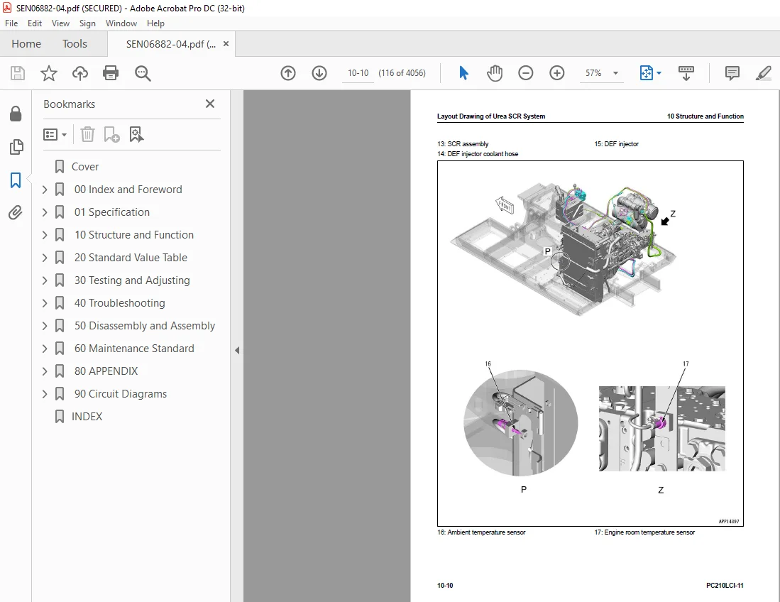
Layout Drawing of Urea SCR System 114
Urea SCR System Diagram 119
Function of Urea SCR System 120
Function of DEF System 120
Inducement Strategy 122
Component Parts of Urea SCR System 130
DEF Mixing Tube 130
SCR Assembly 130
DEF Tank 133
DEF Pump 135
DEF Injector 136
DEF Hose 137
DEF Tank Heating Valve 138
Boot-up System 139
Layout Drawing of Boot-up System 139
System Operating Lamp System 141
System Diagram of System Operating Lamp System 141
Function of Operation Lamp System 141
Battery Disconnect Switch 143
Function of Battery Disconnect Switch 143
Engine System 144
Layout Drawing of Engine System 144
Specifications of Engine System 145
Function of Engine System 145
Engine Control System 146
System Diagram of Engine Control 146
Function of Engine Control System 147
Auto-Deceleration System 149
System Diagram of Auto-Deceleration System 149
Function of Auto-Deceleration System 149
Operation of Auto-Deceleration System 150
Engine Automatic Warm-up System 151
System Diagram of Engine Automatic Warm-up System 151
Function of Engine Automatic Warm-up System 152
Overheat Prevention System 153
Overheat Prevention System Diagram 153
Function of Overheat Prevention System 154
Turbocharger Protection System 156
System Diagram of Turbocharger Protection System 156
Function of Turbocharger Protection System 157
Automatic Idle Stop System 158
System Diagram of Automatic Idle Stop System 158
Function of Automatic Idle Stop System 158
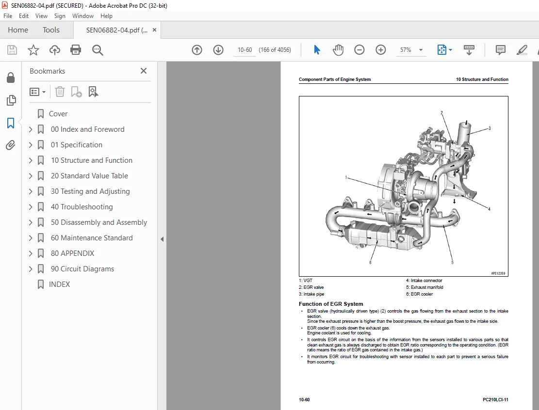
Component Parts of Engine System 161
VGT 161
EGR System 165
EGR Valve 167
EGR Cooler 169
KCCV System 170
KCCV Ventilator 172
KDPF 174
Cooling System 179
Layout Drawing of Cooling System 179
Specifications of Cooling System 180
Fan Speed Control System of Fan Clutch 181
Fan Speed Control System Diagram of Fan Clutch 181
Function of Fan Speed Control System of Fan Clutch 182
Engine Output Control System of Fan Clutch 183
Engine Output Control System Diagram of Fan Clutch 183
Function of Engine Output Control System of Fan Clutch 183
Component Parts of Cooling System 185
Fan Clutch 185
Control System 186
Layout Drawing of Control System 186
Machine Monitor System 189
System Diagram of Machine Monitor System 189
Function of Machine Monitor System 189
KomVision System 191
Layout Drawing of KomVision System 191
System Diagram of KomVision System 193
Function of KomVision System 193
KOMTRAX System 195
System Diagram of KOMTRAX System 195
Function of KOMTRAX System 195
PPC Levers 196
LH PPC Lever 196
RH PPC Lever 197
Automatic Grease System 198
Outline of AUTO Grease System 198
Component Parts of Control System 210
Machine Monitor 210
KomVision Controller 224
KomVision Camera 228
Gateway Function Controller 229
Communication Terminal 232
Pump Controller 234
Resistor for PC-EPC Valve 238
CAN Terminating Resistor 238
Engine Controller 240
Fuel Control Dial 246
Fuel Feed Pump 248
Fuel Feed Pump Switch 249
Hydraulic System 250
Layout Drawing of Hydraulic System 250
CLSS 256
Structure of CLSS 256
Operation of Unload Valve and LS Pressure 258
Pump Swash Plate Angle (Oil Flow) Control 259
Pressure Compensation Control 275
Engine and Pump Combined Control System 279
Engine and Pump Combined Control System Diagram 279
Function of Engine and Pump Combined Control System 280
Pump and Valve Control System 285
Pump and Valve Control System Diagram 285
Function of Pump and Valve Control System 286
Component Parts of Hydraulic System 288
Hydraulic Tank 288
Main Pump 290
Control Valve 312
Work Equipment System 368
Layout Drawing of Work Equipment System 368
Structure of Valve Control 373
Bucket Control System 375
Operation of Bucket Control System 375
One-Touch Power Maximizing System 376
System Diagram of One-Touch Power Maximizing System 376
Function of One-Touch Power Maximizing System 377
PPC Lock System 378
System Diagram of PPC Lock 378
Function of PPC Lock System 378
Work Equipment and Travel Automatic Lock System 379
System Diagram of Lock Lever Automatic Lock System 379
Function of Work Equipment and Travel Automatic Lock System 379
Operation of Lock Lever Automatic Lock System 380
Attachment Oil Flow Adjuster System 381
Attachment Oil Flow Adjuster System Diagram 381
Function of Attachment Oil Flow Adjuster System 382
Tool Control System 383
Tool Control System Diagram 383
Component Parts of Work Equipment System 385
Work Equipment and Swing PPC Valve 385
1st-Line Attachment PPC Valve (with EPC Valve) 391
2nd-Line Attachment PPC Valve 397
Solenoid Valve 399
Boom Anti-drop Valve 402
Arm Anti-Drop Valve 406
Attachment Circuit Selector Valve (For High Pressure) 410
Attachment Circuit Selector Valve (For Low Pressure) 412
1st-Line Attachment Variable Relief Valve 414
2nd-Line Attachment Variable Relief Valve 417
Attachment Bypass Solenoid Valve 420
Pilot Circuit Accumulator 422
Attachment Circuit Accumulator 423
ICT System 424
Layout Drawing of ICT System 424
System Diagram of ICT Control System 427
Bucket Edge Position Detection System 428
Bucket Edge Position Detection System Diagram 428
Function of Bucket Edge Position Detection System 428
Operation of Bucket Edge Position Detection System 428
The Intelligent Machine Control System 430
Function of Intelligent Machine Control System 430
Auto Grade Assist Control 431
Bucket Angle Hold Control 437
Auto Stop Control 439
Tilt Automatic Control (Machines with Auto Tilt Bucket) 453
Cushion System for Arm IN End 456
Cushion System for Arm IN End Diagram 456
Function of Cushion System for Arm IN End 456
Operation of Cushion System for Arm IN End 456
Boom Secondary Drive Switch 458
Control Function When Boom Secondary Drive Switch is Turned to ON Position 458
Component Parts of ICT System 459
ICT Sensor Controller 459
Work Equipment Controller 463
Control Box 467
GNSS Receiver 470
GNSS Antenna 471
IMU Sensor 472
Intelligent Machine Control EPC Valve 474
Stroke Sensor for Boom Cylinder 477
Stroke Sensor for Arm Cylinder 478
Stroke and Reset Sensor for Bucket Cylinder 480
Reset Sensor for Boom Cylinder 482
Reset Sensor for Arm Cylinder 483
Boom Spool Stroke Sensor 484
Arm Spool Stroke Sensor 485
Swing System 487
Layout Drawing of Swing System 487
Swing Control System Diagram 490
Function of Swing Control System 490
Component Parts of Swing System 494
Swing Motor 494
Swing Machinery 505
Swing Circle 506
Travel System 508
Layout Drawing of Travel System 508
System Diagram of Travel Control System 512
Function of Travel Control System 512
Component Parts of Travel System 514
Travel Motor 514
Final Drive 526
Travel PPC Valve 528
Center Swivel Joint 533
Undercarriage and Frame 535
Layout Drawing of Undercarriage 535
Specifications of Undercarriage 536
Work Equipment 537
Structure of Work Equipment 537
Function of Work Equipment 538
Work Equipment Clearance Adjustment Shim 539
Function of Work Equipment Clearance Adjustment Shim 539
Bucket Clearance Adjustment Shim 540
Function of Bucket Clearance Adjustment Shim 540
CAB Related Parts 541
ROPS CAB 541
Structure of ROPS CAB 541
Function of ROPS CAB 541
CAB Mount 542
Structure of CAB Mount 542
Function of CAB Mount 542
CAB Tipping Stopper 543
Structure of CAB Tipping Stopper 543
Function of CAB Tipping Stopper 543
20 Standard Value Table 545
Table of Contents 546
Standard Value Table for Engine 547
Standard Value Table for Engine: PC210LCI-11 547
Standard Value Table for Machine 551
Standard Value Table for Machine: PC210LCI-11 551
Machine Posture and Procedures to Measure Performance 574
30 Testing and Adjusting 579
Table of Contents 580
Related Information on Testing and Adjusting 584
Tools for Testing and Adjusting 584
Sketch of Tools for Testing and Adjusting 594
Engine and Cooling System 596
Examine Engine Speed 596
How to Examine Engine Speed 596
Examine Boost Pressure 599
How to Examine Boost Pressure on Machine Monitor 599
How to Examine Boost Pressure by Testing Tool 600
Examine Exhaust Gas Color 601
How to Examine Exhaust Gas Color with the Handy Smoke Checker 601
How to Examine Exhaust Gas Color with Smoke Meter 602
Examine Mass Air Flow and Temperature Sensor 604
How to Examine Mass Air Flow and Temperature Sensor 604
Examine and Adjust Valve Clearance 606
Check Valve Clearance 606
Adjust Valve Clearance 607
Examine Compression Pressure 609
How to Examine Compression Pressure 609
Examine Blowby Pressure 614
How to Examine Blowby Pressure 614
Examine Engine Oil Pressure 616
How to Examine Engine Oil Pressure 616
Examine EGR Valve and VGT Oil Pressure 617
How to Examine EGR Valve and VGT Oil Pressure 617
Examine Fuel Pressure 619
How to Examine Fuel Pressure 620
Examine Fuel Discharge, Return and Leakage 625
How to Examine Fuel Discharge, Return, and Leakage 626
Bleed Air from Fuel System 632
How to Bleed Air from Fuel System 632
Examine Fuel Circuit for Leakage 633
How to Examine Fuel System for Leakage 633
Handle Cylinder Cut-out Mode Operation 635
Handle No-Injection Cranking Operation 636
Examine and Adjust Air Conditioner Compressor Belt Tension 637
How to Examine Air Conditioner Compressor Belt 637
How to Adjust Air Conditioner Compressor Belt 637
Examine Cooling Fan Speed 639
How to Examine Cooling Fan Speed 639
Write Correction for Ash in Soot Accumulation to Engine Controller 640
How to Write Correction for Ash in Soot Accumulation to Engine Controller 640
Examine SCR Related Functions 641
Examine DEF Pump Raised Pressure 644
Examine Injection Volume from DEF Injector 647
Examine DEF Line Heater Relay 1 651
Examine DEF Line Heater Relay 2 654
Examine DEF Pump Heater Relay 656
Examine DEF Tank Heater Valve 659
Examine SCR Denitration Efficiency 662
Clean DEF Tank 666
How to Clean DEF Tank 666
Clean DEF Pump 670
How to Clean DEF Pump 670
Bleed Air from Coolant Circuit of DEF Tank 677
How to Bleed Air from Coolant Circuit of DEF Tank 677
Power Train 679
Examine Swing Circle Bearing Clearance 679
How to Examine Swing Circle Bearing Clearance 679
Undercarriage and Frame 680
Examine and Adjust Track Tension 680
How to Examine Track Tension 680
How to Adjust Track Tension 680
Hydraulic System 682
Release Remained Pressure in Hydraulic Circuit 682
How to Release Remained Pressure from Hydraulic Tank 682
How to Release Remained Pressure in Hydraulic Cylinder Circuit 682
How to Release Remained Pressure from Swing Motor Circuit 686
How to Release Remained Pressure from Travel Motor Circuit 687
Examine and Adjust Oil Pressure in Work Equipment, Swing, and Travel Circuits 688
How to Examine Oil Pressure in Work Equipment, Swing, and Travel Circuits 689
How to Adjust Oil Pressure in Work Equipment, Swing, and Travel Circuits 695
Examine Oil Pressure of Control Circuit 698
Examine Oil Pressure in Control Circuit 698
Examine and adjust oil pressure in pump PC control circuit 700
Examine PC Valve Outlet Pressure (Servo Piston Inlet Pressure) 700
Examine PC-EPC Valve Outlet Pressure 701
How to Adjust Oil Pressure in Pump PC Control Circuit 702
Examine and Adjust Oil Pressure in Pump LS Control Circuit 704
Examine LS Differential Pressure with Machine Monitor 704
Examine LS Differential Pressure by Testing Tool 705
How to Examine LS Valve Outlet Pressure (Servo Piston Inlet Pressure) 708
How to Examine LS-EPC Valve Outlet Pressure 709
Adjust LS Valve 710
Examine Outlet Pressure of Solenoid Valve 711
How to Examine Outlet Pressure of Solenoid Valve 711
Operating Condition of Solenoid Valve 712
Examine PPC Valve Outlet Pressure 715
Examine Outlet Pressure in PPC Valve 715
Examine Attachment Circuit Oil Pressure 717
How to Examine Attachment Circuit Oil Pressure 717
Adjust Play of Work Equipment and Swing PPC Valves 718
How to Adjust Play of Work Equipment and Swing PPC Valves 718
Examine Pump Swash Plate Sensor 719
How to Examine pump swash plate sensor 719
Examine Parts Which Cause Hydraulic Drift of Work Equipment 720
How to Examine Parts Which Cause Hydraulic Drift of Boom Cylinder and Bucket Cylinder 720
How to Examine the Parts Which Cause Hydraulic Drift of Arm Cylinder 720
How to Examine Parts that Cause Hydraulic Drift of PPC Valve 721
Examine Oil Leakage 722
How to Examine Oil Leakage from Boom Cylinder 722
How to Examine Oil Leakage from Arm Cylinder 722
How to Examine Oil Leakage from Bucket Cylinder 723
How to Examine Oil Leakage from Swing Motor 724
How to Examine Oil Leakage from Travel Motor 724
Bleed Air from Hydraulic System 725
How to Bleed Air from Hydraulic System 727
Work Equipment 729
Examine and Charge Accumulator (Made by NOK) Nitrogen Gas Pressure for Attachment (Low Pressure Side) 729
Examine Accumulator (Made by NOK) Nitrogen Gas Pressure for Attachment (Low Pressure Side) 729
Examine and Charge Accumulator Nitrogen Gas Pressure for Attachment (High Pressure Side) 733
Examine Accumulator Nitrogen Gas Pressure for Attachment (High Pressure Side) 733
Replace Accumulator Bladder on High Pressure Side for Attachment Piping 737
How to Replace Accumulator Bladder on High Pressure Side for Attachment Piping 737
CAB Related Parts 744
Examine CAB Tipping Stopper 744
How to Examine Cab Tipping Stopper 744
How to Adjust Mirrors 745
Procedure to Adjust Machine Left Front Mirror (A) 745
Procedure to Adjust Regular Position of Machine Left Front Mirror (A) 746
Procedure to Adjust Machine Right Front Mirror (B) 747
Procedure to Adjust Regular Position of Machine Right Front Mirror (B) 748
Procedure to Adjust Machine Right Side Mirror (C) 749
Electrical System 751
Set and Operate Machine Monitor 751
Operator Mode 755
Function to Show Technician Identification Status Screen 755
Function to Show Operator Identification Input Screen 755
Examine Function by LCD (Liquid Crystal Display) 756
Examine Function of Service Meter 757
Usage Limitation and Maintenance Password Change Function 757
Service Mode 759
How to Operate Service Mode 759
How to See Pre-defined Monitoring Information 763
How to Examine Self-Define Monitor Information 770
Abnormality Record Menu 783
How to See Maintenance Record 788
Maintenance Mode Setting 789
Set Phone Number Entry 793
Default Menu 794
Diagnostic Tests Menu 804
Adjustment Menu 815
No-Injection Cranking Operation 853
KOMTRAX Settings Menu 854
Show Service Message 856
Start Up KOMTRAX System 858
Adjust rearview camera angle 863
How to Adjust Rearview Camera Angle 863
Adjust KomVision Camera Angle 866
How to Adjust KomVision Camera Angle 867
Adjust KomVision Related Function 871
Setting of KomVision (Main Setting) 871
Setting of KomVision (Camera Setting) 873
Setting of KomVision (Camera Calibration) 875
KomVision screen – Check 12 m visibility 888
Set Region of Bluetooth(R) Compatible Radio 891
Set Region of Bluetooth(R) Compatible Radio 891
Handle Voltage Circuit of Engine Controller 893
Handle Battery Disconnect Switch 894
Examine Diodes 895
Examine Diodes by Digital Tester 895
How to Examine Diodes by Analog Tester 895
ICT System 896
Set and Operate Control Box 896
How to Set the Starting Switch Interlock Function of the Control Box 898
How to Select Excavator Model in the Control Box 901
Set GNSS Receiver Type 905
Set Heading Mode 908
Switch Grade Transitions Fineness on Control Box 912
Monitoring and Logging Function on Control Box 915
Set Tilt Automatic Control Function 920
Calibrate Intelligent Machine Control 924
PPC Pressure Sensor Calibration 926
Control Map Calibration1007
How to Examine the Intelligent Machine Control System1175
Calibrate IMU Sensor for Yaw Angle1181
Calibrate IMU Sensor1188
Procedure to be Done If an Error Occurs During Calibration of IMU Sensor1200
Work Equipment Cylinder Calibration1200
If Error Occurs During Calibration of Work Equipment Cylinder1213
General Calibration of Bucket Blade Edge Position, Boom Dimensions, Arm Dimensions, Bucket Link Dimensions, and GNSS Antenna Position with Total Station1215
Calibration of Boom Dimensions and Arm Dimensions with Total Station1267
Calibration of Bucket Link Dimensions with Total Station1287
Calibration of GNSS Antenna with Total Station1323
Input Range of the Measured Values in Calibration with Total Station1347
Examine the Input Values in Calibration with Total Station1349
Procedure to be Done If an Error Occurs During Calibration with Total Station1349
Calibration of GNSS Antenna Without Total Station1350
Calibration of Bucket Blade Edge Position Without Total Station1354
Input Range of the Measured Values in Calibration Without Total Station1363
Procedure to be Done If an Error Occurs During Calibration Without Total Station1364
Pm Clinic1366
Pm Clinic Service1366
Pm Clinic Check Sheet: PC210LCI-111367
40 Troubleshooting1379
Table of Contents1380
Related Information to Troubleshooting1394
General Troubleshooting Points1394
Troubleshooting Points for Aftertreatment System1395
Table of Failure Codes that is Applied to Inducement1402
Sequence of Events in Troubleshooting1403
Checks Before Troubleshooting1405
Inspection Procedure Before Troubleshooting1407
Walk-Around Check1407
Test in Accordance with Testing Procedure1409
Examine Fuel Level and Type1409
Examine for Impure Ingredient in Fuel1409
Examine Fuel Prefilter1410
Examine Water Separator, Drain Water and Sediment1410
How to Replace Fuel Prefilter Cartridge1411
Examine Fuel Main Filter1412
Examine Engine Oil Level (Oil Quantity in Oil Pan)1414
Examine Coolant Level (Reservoir Tank)1415
Examine Air Cleaner Clogging1415
Clean Outer Element1416
Replace Element1418
Examine Hydraulic Oil Level1419
Examine Hydraulic Oil Strainer1420
Examine Hydraulic Oil Filter1421
Examine Oil Level in Swing Machinery Case1422
Examine Oil Level in Damper Case1423
Examine Oil Level in Final Drive Case1423
Bleed Air from Fuel System1424
Bleed Air from Hydraulic System1424
How to Examine Electric Equipment1424
Preparation for Troubleshooting of Electrical System1432
Preparation for Troubleshooting of Machine Monitor1432
Preparation for Troubleshooting of Engine Controller1432
Preparation for Troubleshooting of ICT Sensor Controller1433
Preparation for Troubleshooting of Work Equipment Controller1434
Preparation for Troubleshooting of Gateway Controller1435
Preparation for Troubleshooting of KomVision Controller1438
Preparation for Troubleshooting of Control Box1439
Preparation for Troubleshooting of GNSS Receiver1439
How to Disconnect and Connect Connector with a Special Lock1439
Procedure for Troubleshooting1443
Symptom and Troubleshooting Numbers1446
Information Shown in Troubleshooting Table1451
Diagnose Open Circuit of Hydraulic Pressure Sensor System Wiring Harness1453
Connector List and Layout1456
Connector Contact Connection Table1479
T-Branch Box and T-Branch Adapter Table1519
Fuse Location Table1525
Precautions When You Clean and Replace KDPF (KCSF and KDOC)1529
Prepare Short Circuit Electrical Connector (For Failure Codes [CA1883] and [CA3135])1533
Failure Code Table1535
Troubleshooting by Failure Code (Display of Code)1561
Failure Code [6AZ0ZG]1561
Failure Code [879AKA]1563
Failure Code [879AKB]1564
Failure Code [879BKA]1565
Failure Code [879BKB]1567
Failure Code [879CKA]1569
Failure Code [879CKB]1570
Failure Code [879DKZ]1571
Failure Code [879EMC]1573
Failure Code [879FMC]1574
Failure Code [879GKX]1575
Failure Code [989L00]1577
Failure Code [989M00]1578
Failure Code [989N00]1579
Failure Code [A1U0N3]1580
Failure Code [A1U0N4]1582
Failure Code [A900FR]1584
Failure Code [A900N6]1585
Failure Code [A900NY]1586
Failure Code [AA10NX]1587
Failure Code [AB00KE]1589
Failure Code [AQ10N3]1592
Failure Code [AS00N3]1593
Failure Code [AS00R2]1595
Failure Code [AS00R3]1596
Failure Code [AS00R4]1597
Failure Code [AS00R5]1598
Failure Code [AS00R6]1599
Failure Code [AS00ZK]1600
Failure Code [AS10KM]1601
Failure Code [AS10NR]1602
Failure Code [AS10NT]1603
Failure Code [B@BAZG]1604
Failure Code [B@BAZK]1605
Failure Code [B@BCNS]1607
Failure Code [B@BCQA]1608
Failure Code [B@BCZK]1610
Failure Code [B@HANS]1612
Failure Code [CA115]1613
Failure Code [CA122]1614
Failure Code [CA123]1616
Failure Code [CA131]1618
Failure Code [CA132]1620
Failure Code [CA144]1622
Failure Code [CA145]1624
Failure Code [CA153]1626
Failure Code [CA154]1629
Failure Code [CA187]1631
Failure Code [CA221]1633
Failure Code [CA222]1635
Failure Code [CA227]1637
Failure Code [CA234]1638
Failure Code [CA238]1639
Failure Code [CA239]1641
Failure Code [CA249]1643
Failure Code [CA256]1645
Failure Code [CA271]1647
Failure Code [CA272]1649
Failure Code [CA322]1651
Failure Code [CA323]1653
Failure Code [CA324]1655
Failure Code [CA325]1657
Failure Code [CA331]1659
Failure Code [CA332]1661
Failure Code [CA343]1663
Failure Code [CA351]1664
Failure Code [CA352]1665
Failure Code [CA356]1668
Failure Code [CA357]1670
Failure Code [CA386]1672
Failure Code [CA428]1673
Failure Code [CA429]1675
Failure Code [CA435]1677
Failure Code [CA441]1679
Failure Code [CA442]1681
Failure Code [CA449]1682
Failure Code [CA451]1683
Failure Code [CA452]1685
Failure Code [CA488]1687
Failure Code [CA515]1688
Failure Code [CA516]1690
Failure Code [CA553]1692
Failure Code [CA555]1693
Failure Code [CA556]1694
Failure Code [CA559]1695
Failure Code [CA595]1698
Failure Code [CA687]1699
Failure Code [CA689]1701
Failure Code [CA691]1704
Failure Code [CA692]1706
Failure Code [CA697]1708
Failure Code [CA698]1709
Failure Code [CA731]1710
Failure Code [CA778]1712
Failure Code [CA1117]1717
Failure Code [CA1664]1718
Failure Code [CA1669]1720
Failure Code [CA1673]1721
Failure Code [CA1677]1722
Failure Code [CA1678]1723
Failure Code [CA1682]1724
Failure Code [CA1683]1726
Failure Code [CA1684]1728
Failure Code [CA1686]1730
Failure Code [CA1691]1731
Failure Code [CA1694]1734
Failure Code [CA1695]1737
Failure Code [CA1696]1738
Failure Code [CA1712]1740
Failure Code [CA1713]1743
Failure Code [CA1714]1745
Failure Code [CA1715]1746
Failure Code [CA1776]1747
Failure Code [CA1777]1750
Failure Code [CA1843]1753
Failure Code [CA1844]1755
Failure Code [CA1879]1758
Failure Code [CA1881]1760
Failure Code [CA1883]1762
Failure Code [CA1885]1765
Failure Code [CA1887]1767
Failure Code [CA1921]1769
Failure Code [CA1922]1772
Failure Code [CA1942]1777
Failure Code [CA1993]1778
Failure Code [CA2185]1781
Failure Code [CA2186]1782
Failure Code [CA2249]1784
Failure Code [CA2271]1785
Failure Code [CA2272]1788
Failure Code [CA2288]1791
Failure Code [CA2311]1792
Failure Code [CA2349]1793
Failure Code [CA2353]1796
Failure Code [CA2357]1798
Failure Code [CA2381]1799
Failure Code [CA2382]1802
Failure Code [CA2383]1805
Failure Code [CA2386]1808
Failure Code [CA2387]1810
Troubleshooting Flowchart1814
Failure Code [CA2555]1815
Failure Code [CA2556]1818
Failure Code [CA2637]1821
Failure Code [CA2639]1823
Failure Code [CA2771]1826
Failure Code [CA2777]1832
Failure Code [CA2976]1835
Failure Code [CA3133]1837
Failure Code [CA3134]1840
Failure Code [CA3135]1842
Failure Code [CA3142]1845
Failure Code [CA3143]1846
Failure Code [CA3144]1847
Failure Code [CA3146]1849
Failure Code [CA3147]1850
Failure Code [CA3148]1851
Failure Code [CA3151]1853
Failure Code [CA3165]1859
Failure Code [CA3229]1861
Failure Code [CA3231]1863
Failure Code [CA3232]1865
Failure Code [CA3235]1869
Failure Code [CA3239]1871
Failure Code [CA3241]1874
Failure Code [CA3242]1877
Failure Code [CA3251]1880
Failure Code [CA3253]1882
Failure Code [CA3254]1885
Failure Code [CA3255]1888
Failure Code [CA3256]1892
Failure Code [CA3311]1894
Failure Code [CA3312]1896
Failure Code [CA3313]1899
Failure Code [CA3314]1900
Failure Code [CA3315]1901
Failure Code [CA3316]1903
Failure Code [CA3317]1904
Failure Code [CA3318]1905
Failure Code [CA3319]1907
Failure Code [CA3321]1908
Failure Code [CA3322]1910
Failure Code [CA3419]1912
Failure Code [CA3421]1914
Failure Code [CA3497]1916
Failure Code [CA3498]1917
Failure Code [CA3543]1918
Failure Code [CA3545]1925
Failure Code [CA3547]1927
Failure Code [CA3558]1928
Failure Code [CA3559]1930
Failure Code [CA3562]1932
Failure Code [CA3563]1934
Failure Code [CA3567]1937
Failure Code [CA3568]1940
Failure Code [CA3571]1944
Failure Code [CA3572]1946
Failure Code [CA3574]1948
Failure Code [CA3575]1950
Failure Code [CA3577]1952
Failure Code [CA3578]1954
Failure Code [CA3582]1956
Failure Code [CA3583]1962
Failure Code [CA3596]1964
Failure Code [CA3649]1966
Failure Code [CA3681]1968
Failure Code [CA3682]1973
Failure Code [CA3713]1979
Failure Code [CA3717]1982
Failure Code [CA3718]1983
Failure Code [CA3725]1984
Failure Code [CA3741]1987
Failure Code [CA3748]1988
Failure Code [CA3751]1990
Failure Code [CA3755]1992
Failure Code [CA3866]1994
Failure Code [CA3867]1998
Failure Code [CA3868]2001
Failure Code [CA3899]2005
Failure Code [CA3911]2007
Failure Code [CA3912]2011
Failure Code [CA3932]2013
Failure Code [CA3933]2015
Failure Code [CA3934]2017
Failure Code [CA3935]2020
Failure Code [CA3936]2022
Failure Code [CA4151]2024
Failure Code [CA4152]2028
Failure Code [CA4155]2032
Failure Code [CA4156]2034
Failure Code [CA4157]2037
Failure Code [CA4158]2039
Failure Code [CA4159]2040
Failure Code [CA4161]2041
Failure Code [CA4162]2044
Failure Code [CA4163]2047
Failure Code [CA4164]2048
Failure Code [CA4165]2050
Failure Code [CA4166]2052
Failure Code [CA4168]2053
Failure Code [CA4169]2056
Failure Code [CA4171]2058
Failure Code [CA4249]2061
Failure Code [CA4251]2063
Failure Code [CA4259]2065
Failure Code [CA4261]2068
Failure Code [CA4277]2071
Failure Code [CA4281]2075
Failure Code [CA4459]2078
Failure Code [CA4461]2080
Failure Code [CA4658]2083
Failure Code [CA4731]2087
Failure Code [CA4732]2088
Failure Code [CA4739]2089
Failure Code [CA4768]2090
Failure Code [CA4769]2092
Failure Code [CA4842]2095
Failure Code [CA4952]2099
Failure Code [CA5115]2101
Failure Code [CA5179]2104
Failure Code [CA5181]2106
Failure Code [CA5383]2108
Failure Code [D110KB]2110
Failure Code [D19JKZ]2112
Failure Code [D1M3KA]2115
Failure Code [D1M3KB]2117
Failure Code [D1M3KY]2119
Failure Code [D1M3MA]2121
Failure Code [D1M4KA]2122
Failure Code [D1M4KB]2124
Failure Code [D1M4KY]2126
Failure Code [D1M5KA]2127
Failure Code [D1M5KB]2129
Failure Code [D1M5KY]2131
Failure Code [D1M5MA]2133
Failure Code [D811MC]2134
Failure Code [D862KA]2135
Failure Code [D8ALKA]2137
Failure Code [D8ALKB]2140
Failure Code [D8AQKR]2143
Failure Code [D8G1KT]2151
Failure Code [D8G6KT]2152
Failure Code [DA20MC]2153
Failure Code [DA22KK]2154
Failure Code [DA25KP]2157
Failure Code [DA26KP]2161
Failure Code [DA29KQ]2163
Failure Code [DA2LKA]2166
Failure Code [DA2LKB]2170
Failure Code [DA2QKR]2173
Failure Code [DA2RKR]2183
Failure Code [DAF0KM]2192
Failure Code [DAF0MB]2193
Failure Code [DAF0MC]2194
Failure Code [DAF8KB]2195
Failure Code [DAF9KQ]2197
Failure Code [DAFGMC]2198
Failure Code [DAFLKA]2199
Failure Code [DAFLKB]2203
Failure Code [DAFQKR]2206
Failure Code [DAZ9KQ]2215
Failure Code [DAZQKR]2216
Failure Code [DB2QKR]2224
Failure Code [DB2RKR]2233
Failure Code [DB90MC]2241
Failure Code [DB92KK]2242
Failure Code [DB95KP]2244
Failure Code [DB96KP]2248
Failure Code [DB99KQ]2252
Failure Code [DB9LKA]2255
Failure Code [DB9LKB]2259
Failure Code [DB9QKR]2262
Failure Code [DB9RKR]2272
Failure Code [DBP0KM]2281
Failure Code [DBP0KT]2282
Failure Code [DBP5KB]2283
Failure Code [DBP5KY]2286
Failure Code [DBPQKR]2289
Failure Code [DBR0MC]2298
Failure Code [DBR2KK]2299
Failure Code [DBR5KP]2302
Failure Code [DBR6KP]2304
Failure Code [DBR9KQ]2306
Failure Code [DBRLKA]2309
Failure Code [DBRLKB]2313
Failure Code [DBRQKR]2316
Failure Code [DBRRKR]2325
Failure Code [DBRSKB]2334
Failure Code [DBRTKB]2336
Failure Code [DBUSKR]2338
Failure Code [DD20MA]2342
Failure Code [DDNRKA]2345
Failure Code [DDNRKY]2347
Failure Code [DDNS00]2349
Failure Code [DFB1KZ]2351
Failure Code [DFB2KZ]2353
Failure Code [DFB3L8]2355
Failure Code [DFB4L8]2357
Failure Code [DFB5KZ]2359
Failure Code [DFB6KZ]2361
Failure Code [DGH2KA]2363
Failure Code [DGH2KB]2365
Failure Code [DHA4KA]2367
Failure Code [DHAAMA]2369
Failure Code [DHACMA]2371
Failure Code [DHPAMA]2373
Failure Code [DHPBMA]2375
Failure Code [DHS3MA]2377
Failure Code [DHS4MA]2380
Failure Code [DHS8MA]2383
Failure Code [DHS9MA]2386
Failure Code [DHSAMA]2389
Failure Code [DHSBMA]2392
Failure Code [DHSCMA]2395
Failure Code [DHSDMA]2398
Failure Code [DHSFMA]2401
Failure Code [DHSGMA]2404
Failure Code [DHSHMA]2407
Failure Code [DHSJMA]2410
Failure Code [DHUXMA]2413
Failure Code [DHUYMA]2415
Failure Code [DHZAMA]2417
Failure Code [DHZCL8]2421
Failure Code [DK80KM]2422
Failure Code [DK80KR]2423
Failure Code [DK80KT]2428
Failure Code [DK8DKB]2429
Failure Code [DK8CKT]2431
Failure Code [DK8CKR]2432
Failure Code [DKG1KM]2436
Failure Code [DKG1L8]2437
Failure Code [DKR0MA]2438
Failure Code [DKR1MA]2440
Failure Code [DKT0KM]2442
Failure Code [DKT0L8]2443
Failure Code [DKT1KA]2444
Failure Code [DKT1KB]2446
Failure Code [DKT2KA]2448
Failure Code [DKT2KB]2450
Failure Code [DKT4KM]2452
Failure Code [DKT4L8]2453
Failure Code [DKT5KA]2454
Failure Code [DKT5KB]2456
Failure Code [DKT6KA]2458
Failure Code [DKT6KB]2460
Failure Code [DKT8KA]2462
Failure Code [DKT8KB]2464
Failure Code [DKT9KA]2466
Failure Code [DKT9KB]2468
Failure Code [DKTAKA]2470
Failure Code [DKTAKB]2472
Failure Code [DKTAMB]2474
Failure Code [DKTBKX]2475
Failure Code [DKTBMC]2477
Failure Code [DKTEMB]2478
Failure Code [DKTFKX]2480
Failure Code [DKTFMC]2482
Failure Code [DKTJMB]2483
Failure Code [DKTUL8]2485
Failure Code [DKTVKA]2486
Failure Code [DKTVKB]2488
Failure Code [DKTWKA]2489
Failure Code [DKTWKB]2491
Failure Code [DKU1MA]2492
Failure Code [DKU2MA]2493
Failure Code [DKUGKA]2494
Failure Code [DKUGKB]2496
Failure Code [DKUGKY]2498
Failure Code [DKUHKA]2500
Failure Code [DKUHKB]2502
Failure Code [DKUHKY]2504
Failure Code [DKULKA]2506
Failure Code [DKULKB]2508
Failure Code [DKULKY]2510
Failure Code [DKV0KA]2512
Failure Code [DKV0KY]2515
Failure Code [DKV1KA]2517
Failure Code [DKV1KY]2519
Failure Code [DKV2KA]2521
Failure Code [DKV2KY]2523
Failure Code [DKV3KA]2525
Failure Code [DKV3KY]2527
Failure Code [DKV4MA]2529
Failure Code [DKV5MA]2532
Failure Code [DKV6MA]2535
Failure Code [DKV7MA]2538
Failure Code [DKV8MA]2541
Failure Code [DKV9MA]2544
Failure Code [DKVAMA]2547
Failure Code [DKVBKA]2550
Failure Code [DKVBKB]2552
Failure Code [DKVBKY]2554
Failure Code [DKVCKA]2556
Failure Code [DKVCKB]2558
Failure Code [DKVCKY]2560
Failure Code [DKVDKA]2562
Failure Code [DKVDKB]2564
Failure Code [DKVDKY]2566
Failure Code [DKVDMA]2568
Failure Code [DKVLMA]2570
Failure Code [DKVMMA]2573
Failure Code [DKVNKX]2576
Failure Code [DKVNL8]2577
Failure Code [DKVKKX]2578
Failure Code [DKVKL8]2579
Failure Code [DKVPMA]2580
Failure Code [DKVQMA]2583
Failure Code [DLM5KA]2586
Failure Code [DLM5MB]2588
Failure Code [DR10KA]2590
Failure Code [DR12KA]2593
Failure Code [DR20KA]2595
Failure Code [DR21KX]2597
Failure Code [DR30KA]2599
Failure Code [DR31KX]2601
Failure Code [DR40KA]2603
Failure Code [DUMBKA]2605
Failure Code [DUMBKB]2609
Failure Code [DV20KB]2612
Failure Code [DW43KA]2614
Failure Code [DW43KB]2616
Failure Code [DW43KY]2618
Failure Code [DW45KA]2620
Failure Code [DW45KB]2623
Failure Code [DW45KY]2626
Failure Code [DW4CKY]2628
Failure Code [DW4FKA]2630
Failure Code [DW4FKB]2633
Failure Code [DW4FKY]2635
Failure Code [DW4GKA]2638
Failure Code [DW4GKB]2641
Failure Code [DW4GKY]2643
Failure Code [DW4SKA]2645
Failure Code [DW4SKB]2647
Failure Code [DW4SKY]2649
Failure Code [DW91KA]2651
Failure Code [DW91KB]2653
Failure Code [DW91KY]2655
Failure Code [DWA2KA]2657
Failure Code [DWA2KB]2659
Failure Code [DWA2KY]2661
Failure Code [DWK0KA]2663
Failure Code [DWK0KB]2665
Failure Code [DWK0KY]2667
Failure Code [DWK2KA]2669
Failure Code [DWK2KB]2671
Failure Code [DWK2KY]2673
Failure Code [DWK8KA]2675
Failure Code [DWK8KB]2677
Failure Code [DWK8KY]2679
Failure Code [DWN5KA]2681
Failure Code [DWN5KB]2683
Failure Code [DWN5KY]2685
Failure Code [DWPUKA]2687
Failure Code [DWPUKB]2689
Failure Code [DWPUKY]2691
Failure Code [DXA8KA]2692
Failure Code [DXA8KB]2694
Failure Code [DXA9KA]2696
Failure Code [DXA9KB]2698
Failure Code [DXE0KA]2700
Failure Code [DXE0KB]2701
Failure Code [DXE4KA]2703
Failure Code [DXE4KB]2705
Failure Code [DXE4KY]2707
Failure Code [DXE5KA]2709
Failure Code [DXE5KB]2711
Failure Code [DXE6KA]2713
Failure Code [DXE6KB]2715
Failure Code [DXE7KA]2717
Failure Code [DXE7KB]2719
Failure Code [DXE7KY]2721
Failure Code [DXE8KA]2723
Failure Code [DXE8KB]2725
Failure Code [DXE8KY]2727
Failure Code [DXE9KA]2729
Failure Code [DXE9KB]2731
Failure Code [DXE9KY]2733
Failure Code [DXEAKA]2735
Failure Code [DXEAKB]2737
Failure Code [DXEAKY]2739
Failure Code [DXEKKA]2741
Failure Code [DXEKKB]2743
Failure Code [DXEKKY]2745
Failure Code [DXELKA]2746
Failure Code [DXELKB]2748
Failure Code [DXELKY]2750
Failure Code [DXRWKA]2751
Failure Code [DXRWKB]2753
Failure Code [DXRWKY]2755
Failure Code [DXRXKA]2757
Failure Code [DXRXKB]2759
Failure Code [DXRXKY]2761
Failure Code [DXRYKA]2763
Failure Code [DXRYKB]2765
Failure Code [DXRYKY]2767
Failure Code [DY20KA]2769
Failure Code [DY20MA]2771
Failure Code [DY2CKB]2773
Failure Code [DY2DKB]2776
Failure Code [DY2EKB]2778
Failure Code [F311KA]2780
Failure Code [F311KB]2782
Failure Code [F312KA]2784
Failure Code [F312KB]2786
Failure Code [F313KA]2788
Failure Code [F313KB]2790
Failure Code [F314KA]2793
Failure Code [F314KB]2795
Failure Code [F315KB]2797
Failure Code [F315KY]2799
Failure Code [F316KB]2801
Failure Code [F316KY]2803
Failure Code [F318KB]2805
Failure Code [F318KY]2808
Failure Code [F31AKB]2810
Failure Code [F31AKY]2812
Failure Code [F31BKB]2814
Failure Code [F31BKY]2816
Failure Code [F31CKB]2818
Failure Code [F31CKY]2820
Failure Code [F31DKB]2822
Failure Code [F31DKY]2824
Failure Code [F31EKB]2826
Failure Code [F31EKY]2828
Failure Code [F7FQKR]2830
Failure Code [F7G0MC]2839
Failure Code [H16SL8]2840
Failure Code [H17SL8]2842
Troubleshooting of Electrical System (E-Mode)2844
Engine Does Not Start (Engine Does Not Crank)2844
Manual Preheating System Does Not Operate2850
Automatic Preheating System Does Not Operate2853
While Preheating is in Operation, Preheating Monitor Does Not Come On2855
When Starting Switch is Turned to ON Position, Machine Monitor Shows Nothing2857
While Starting Switch is Turned to ON Position (with Engine Stopped), Engine Oil Level Monitor Comes On in Yellow2860
While Starting Switch is Turned to ON Position (with Engine Stopped), Radiator Coolant Level Monitor Comes On in Yellow2861
Engine Coolant Temperature Monitor Comes On in White While Engine is in Operation2862
Hydraulic Oil Temperature Monitor Comes On in White While Engine is in Operation2863
Air Cleaner Clogging Monitor Comes On in Yellow While Engine is in Operation2864
Charge Level Monitor Comes On in Red While Engine is in Operation2865
Fuel Level Monitor Comes On in Red While Engine is in Operation2866
Water Separator Monitor Comes On in Red While Engine is in Operation2867
Engine Coolant Temperature Monitor Comes On in Red While Engine is in Operation2868
Engine Oil Pressure Monitor Comes On in Red While Engine is in Operation2869
Hydraulic Oil Temperature Monitor Comes On in Red While Engine is in Operation2870
Fuel Gauge Does Not Move from Minimum or Maximum2871
Display of Fuel Gauge is Different from Actual Fuel Level2873
Engine Coolant Temperature Gauge Display Does Not Move from Minimum or Maximum2874
Display of Engine Coolant Temperature Gauge is Different from Actual Coolant Temperature2875
Hydraulic Oil Temperature Gauge Does Not Move from Minimum or Maximum2876
Display of Hydraulic Oil Temperature Gauge is Different from Actual Oil Temperature2878
Some Areas of Machine Monitor Screen are Not Shown2879
Function Switch Does Not Operate2880
Automatic Warm-up System Does Not Operate (in Cold Weather)2881
Auto-Deceleration Monitor Does Not Come On or Go Out While Auto-Deceleration Switch is Operated2882
Auto-Decelerator is Not Operated or Canceled with Lever2883
Work Mode Selector Screen is Not Shown While Work Mode Switch is Operated2884
When Working Mode is Changed, Setting of Engine and Hydraulic Pump is Not Changed2885
Travel Speed Monitor Does Not Change While Travel Speed Switch is Operated2886
Travel Speed Does Not Change Even When You Change Travel Speed2887
Alarm Buzzer Does Not Stop2889
Service Meter is Not Shown While Starting Switch is in OFF Position2890
Service Mode Cannot be Selected2891
All Work Equipment, Swing, Travel Do Not Operate2892
All Work Equipment, Swing, Travel Cannot be Locked2895
Bucket Does Not Move with Auto Tilt Function2897
Machine Does Not Swing While Swing Parking Brake Release Switch is Set to Release Position2898
While Swing Parking Brake Release Switch is Turned on, Swing Brake is Not Operated2901
One-Touch Power Maximizing Function Does Not Operate Correctly or Monitor is Not Shown2903
One-Touch Power Maximizing Function is Not Cancelled2906
Travel Alarm Does Not Operate During Travel2907
Travel Alarm Does Not Stop When Machine Stops2909
Horn Does Not Sound2910
Horn Does Not Stop2913
Wiper Monitor Does Not Come On or Go Out While Wiper Switch is Operated2915
Windshield Wiper Does Not Operate When Wiper Switch is Operated2916
When Window Washer Switch is Operated, Window Washer Does Not Operate2918
“Boom Raise” is Not Shown Correctly with Monitoring Function2919
“Boom Lower” is Not Shown Correctly with Monitoring Function2920
“Arm OUT” is Not Shown Correctly with Monitoring Function2921
“Arm IN” is Not Shown Correctly with Monitoring Function2922
Bucket DUMP is Not Shown Correctly with Monitoring Function2923
Bucket CURL is Not Shown Correctly with Monitoring Function2924
Swing is Not Shown Correctly with Monitoring Function2925
Travel is Not Shown Correctly with Monitoring Function2926
Service is Not Shown Correctly with Monitoring Function2927
Attachment Hydraulic Circuit Cannot be Changed2929
KOMTRAX System Does Not Operate Correctly2930
Control Box Shuts Down After It Shows Messages [GPS receiver not connected!] and [Slope sensor not connected!]2931
Control Box Shows Message [GPS receiver not connected!]2934
Control Box Shows Message [Waiting for radio link]2937
Control Box Shows Message [Tilt Bucket Sensor Offline!]2938
Control Box Shows Message [Waiting for satellites]2939
Control Box Shows Message [GPS receiver not connected!] Show Production2940
Control Box Shows Message [Sensors are invalid]2943
Control Box Shows Message [Waiting to initialize]2946
Control Box Shows Message [Initializing]2947
Control Box Shows Message [No GPS Localization]2948
Control Box Shows Message [Low precisions]2949
Control Box Displays [Out of design area]2950
Control Box Shows Message [Avoidance Area Breach!]2951
Control Box Shows Message [CPU Load is Increased]2952
Control Box Can Not be Turned on2953
Control Box Does Not Display Intelligent Machine Control Screen2954
Control Box Does Not Display Hydraulic Excavator Image2955
Control Box Does Not Display Design Surface2956
Control Box Touch Panel Does Not Respond2957
Control Box Touch Panel is Inaccurate2958
When You Examine and Adjust the Bucket Edge Position, the Value is Different from Actual Machine2959
Semi-Auto Mode is Not Shown When Auto/Manual Switch is Pushed2961
Auto Grade Assist Control Does Not Operate While “Semi-auto limited digging mode” is Shown2962
Auto Stop Control Does Not Operate While “Semi-Auto Mode” is Shown2963
“Semi-auto limited digging mode” is Shown but the Work Mode Icon is Not Shown2964
Bucket Angle Hold Control Does Not Operate2965
Blade Edge Position on Design Surface is Not Accurate When Auto Grade Assist Function is on2966
Blade Edge Stop Position is Not Accurate for Design Surface When Auto Stop Control Function is on2968
Facing Angle Compass Does Not Become Perpendicular to Target2970
NG Occurs Frequently in IMU Calibration Diagnosis2971
Cushion for Boom Raise End Does Not Work or is Weak2972
Cushion for Arm IN End Does Not Work or is Weak2973
Troubleshooting for Hydraulic and Mechanical Systems (H Mode)2976
Information Shown in Troubleshooting Table (H-Mode)2976
System Chart of Hydraulic and Mechanical Systems2977
Failure Mode and Cause Table2979
H-1 All Work Equipment, Swing and Travel Do Not Work2988
H-2 All Work Equipment, Swing and Travel Lack Speed and Power2989
H-3 Fine Control Performance or Response is Unsatisfactory2992
H-4 Unusual Noise is Heard from Around Hydraulic Pump2993
H-5 Engine Speed Drops Largely or Engine Stops2994
H-6 Speed or Power of Boom is Low2996
H-7 Arm Speed or Power is Low3000
H-8 Bucket Speed or Power is Low3005
H-9 Bucket Does Not Move in Single Operation with Auto Tilt Function3008
H-10 Work Equipment Does Not Move in Single Operation3009
H-11 Hydraulic Drift of Boom is Large3010
H-12 Hydraulic Drift of Arm is Large3012
H-13 Hydraulic Drift of Bucket is Large3014
H-14 When Single Work Equipment is Released Hydraulically, Other Work Equipment Moves3015
H-15 Time Lag of Work Equipment is Large3016
H-16 One-Touch Power Maximizing Function Does Not Operate3017
H-17 Attachment Circuit Cannot be Changed3018
H-18 Oil Flow in Attachment Circuit Cannot be Changed3019
H-19 In Mixed Operation of Work Equipment, Work Equipment with Heavier Load Moves Slower3020
H-20 In Mixed Operation of Swing and Travel, Travel Speed Drops Largely3021
H-21 In Mixed Operation of Swing and Boom Raise, Boom Raise Speed is Low3022
H-22 Machine Does Not Travel Straight3023
H-23 Machine is Not Steered Correctly or Steering Power is Low3025
H-24 Travel Speed is Low3028
H-25 One of Tracks Does Not Run3030
H-26 Travel Speed Does Not Change, or Travel Speed is Too Slow or Fast3031
H-27 Machine Does Not Swing to Right or Left3032
H-28 Upper Structure Swings Only to Right or Left3033
H-29 Swing Acceleration or Swing Speed is Low in Two Directions of Right and Left3034
H-30 Swing Acceleration or Swing Speed is Low in Only One Direction3035
H-31 Upper Structure Overruns Too Much When It Stops Swing Operation (Right and Left)3036
H-32 Upper Structure Overruns Too Much When It Stops Swing Operation (Only One Direction)3037
H-33 Shock is Large When Upper Structure Stops Swing Operation3038
H-34 There is Large Unusual Noise When It Stops Swing Operation3039
H-35 Swing Drift on a Slope is Large (While Swing Parking Brake is Applied)3040
H-36 Swing Drift on a Slope is Large (While Swing Parking Brake is Released)3041
H-37 Fan Speed is Abnormal (Too High or Low, or Does Not Rotate)3042
H-38 Unusual Noise is Heard from Around Fan3043
Troubleshooting of Engine (S-Mode)3044
Information Shown in Troubleshooting Table (S-Mode)3044
S-1 Engine Does Not Crank When Starting Switch is Turned to Start Position3045
S-2 Engine Cranks but No Exhaust Smoke Comes Out3046
S-3 Fuel is Injected but Engine Does Not Start (Misfiring: Engine Cranks but Does Not Start)3047
S-4 Engine Startability is Unsatisfactory3049
S-5 Engine Does Not Pick Up Smoothly3051
S-6 Engine Stops During Operation3053
S-7 Engine Runs Rough or is Not Stable3055
S-8 Engine Lacks Power3056
S-9 KDPF Becomes Clogged in a Short Time3058
S-10 Engine Oil Consumption is Excessive3060
S-11 Oil Becomes Dirty Quickly3061
S-12 Fuel Consumption is Excessive3062
S-13 Oil is in Coolant (or Coolant Spurts Back or Coolant3063
S-14 Oil Pressure Drops3064
S-15 Fuel Mixes Into Engine Oil3066
S-16 Water Mixes Into Engine Oil (Milky)3067
S-17 Coolant Temperature Increases Too High (Overheating)3068
S-18 Unusual Noise is Heard3069
S-19 Vibration is Excessive3070
S-20 Air Cannot be Bled from Fuel Circuit3071
S-21 Active Regeneration is Done Frequently3072
S-22 Active Regeneration Continues Long3074
S-23 White Smoke is Exhausted During Active Regeneration3075
S-24 DEF Consumption is Excessive3076
S-25 There is Unusual Smell (Irritating Odor)3078
S-26 Foreign Materials Enter DEF (DEF Increases)3079
50 Disassembly and Assembly3081
Table of Contents3082
Related Information on Disassembly and Assembly3088
How to Read This Manual3088
Coating Materials List3089
Special Tool List3094
Sketches of Special Tools3106
Engine and Cooling System3112
Remove and Install Supply Pump Assembly3112
Remove Supply Pump Assembly3112
Install Supply Pump Assembly3115
Remove and Install Injector Assembly3118
How to Remove Injector Assembly3118
How to Install Injector Assembly3123
Remove and Install Cylinder Head Assembly3131
How to Remove Cylinder Head Assembly3132
How to Install Cylinder Head Assembly3141
Remove and Install EGR Valve Assembly3157
Remove EGR Valve Assembly3157
Install EGR Valve Assembly3158
Remove and Install EGR Cooler Assembly3160
How to Remove EGR Cooler Assembly3160
How to Install EGR Cooler Assembly3164
Remove and Install Starter Assembly3169
Remove Starting Motor Assembly3169
Install Starting Motor Assembly3170
Remove and Install Alternator Belt3173
Remove Alternator Belt3173
Install Alternator Belt3175
Remove and Install Radiator Assembly3178
How to Remove Radiator Assembly3178
How to Install Radiator Assembly3180
Remove and Install Hydraulic Oil Cooler Assembly3183
How to Remove Hydraulic Oil Cooler Assembly3183
How to Install Hydraulic Oil Cooler Assembly3186
Remove and Install Aftercooler Assembly3189
Remove Aftercooler Assembly3189
Install Aftercooler Assembly3191
Remove and Install Fan Clutch Assembly3193
How to Remove Fan Clutch Assembly3193
How to Install Fan Clutch Assembly3198
Remove and Install Fan3202
Remove Fan3202
Install Fan3202
Remove and Install Engine and Main Pump Assembly3203
Remove Engine and Main Pump Assembly3203
Install Engine and Main Pump Assembly3212
Remove and Install Engine Front Oil Seal3224
How to Remove Engine Front Oil Seal3224
How to Install Engine Front Oil Seal3227
Remove and Install Engine Rear Oil Seal3231
How to Remove Engine Rear Oil Seal3231
How to Install Engine Rear Oil Seal3232
Remove and Install Fuel Cooler Assembly3235
Remove Fuel Cooler Assembly3235
Install Fuel Cooler Assembly3235
Remove and Install Engine Hood Assembly3237
How to Remove Engine Hood Assembly3237
How to Install Engine Hood Assembly3239
Remove and Install Fuel Tank Assembly3244
Remove Fuel Tank Assembly3244
Install Fuel Tank Assembly3248
Remove and Install DEF Tank Assembly3254
How to Remove DEF Tank Assembly3254
How to Install DEF Tank Assembly3260
Remove and Install DEF Tank Sensor Flange Assembly3266
How to Remove DEF Tank Sensor Flange Assembly3266
How to Install DEF Tank Sensor Flange Assembly3272
Remove and Install DEF Tank Sensor3278
Remove DEF Tank Sensor3278
Install DEF Tank Sensor3278
Remove and Install DEF Tank Strainer3285
Remove DEF Tank Strainer3285
Install DEF Tank Strainer3285
Remove and Install DEF Tank Filler Port Filter3286
Remove DEF Tank Filler Port Filter3286
Install DEF Tank Filler Port Filter3288
Remove and Install KDPF Assembly3291
How to Remove KDPF Assembly3291
How to Install KDPF Assembly3293
Disassemble and Assemble KDPF Assembly3295
Disassemble KDPF Assembly3296
Assemble KDPF Assembly3299
Remove and Install SCR Assembly3304
How to Remove SCR Assembly3304
How to Install SCR Assembly3306
Remove and Install KDPF and SCR Assembly3308
How to Remove KDPF and SCR Assembly3308
Install KDPF and SCR Assembly3315
Remove and Install KDPF and SCR Assembly Bracket3321
Remove KDPF and SCR Assembly Bracket3321
Install KDPF and SCR Assembly Bracket3328
Remove and Install Bellows Pipe Assembly3335
How to Remove Bellows Pipe Assembly3335
How to Install Bellows Pipe Assembly3337
Remove and Install KCCV Assembly3341
Remove KCCV Assembly3341
Install KCCV Assembly3343
Remove and Install DEF Mixing Tube3348
Remove DEF Mixing Tube3348
Install DEF Mixing Tube3354
Remove and Install DEF Injector3360
Remove DEF Injector3360
Install DEF Injector3363
Remove and Install DEF Pump3366
Remove DEF Pump3366
Install DEF Pump3369
Remove and Install DEF Hose3372
Remove DEF Hose3372
Install DEF Hose3380
Remove and Install Air Cleaner Assembly3386
Remove Air Cleaner Assembly3386
Install Air Cleaner Assembly3387
Remove and Install Air Conditioner Compressor Assembly3389
Remove Air Conditioner Compressor Assembly3389
How to Install Air Conditioner Compressor Assembly3391
Remove and Install Air Conditioner Condenser Assembly3394
How to Remove Air Conditioner Condenser Assembly3394
How to Install Air Conditioner Condenser Assembly3395
Power Train3396
Remove and Install Travel Motor and Final Drive Assembly3396
Remove Travel Motor and Final Drive Assembly3396
Install Travel Motor and Final Drive Assembly3397
Disassemble and Assemble Final Drive Assembly3399
Disassemble Final Drive Assembly3399
Assemble Final Drive Assembly3403
Remove and Install Swing Motor and Swing Machinery Assembly3412
Remove Swing Motor and Swing Machinery Assembly3412
Install Swing Motor and Swing Machinery Assembly3414
Disassemble and Assemble Swing Machinery Assembly3418
Disassemble Swing Machinery Assembly3418
Assemble Swing Machinery Assembly3422
Remove and Install Swing Circle Assembly3429
Install Swing Circle Assembly3429
Remove Swing Circle Assembly3430
Undercarriage and Frame3431
Separate and Connect Track Assembly3431
Separate Track Assembly3431
Install Track Assembly3433
Remove and Install Sprocket3436
Remove Sprocket3436
Install Sprocket3436
Remove and Install Idler and Idler Cushion Assembly3438
Remove Idler and Idler Cushion Assembly3438
Install Idler and Idler Cushion Assembly3439
Disassemble and Assemble Idler Assembly3440
Disassemble Idler Assembly3440
Assemble Idler Assembly3441
Disassemble and Assemble Idler Cushion Assembly3445
Disassemble Idler Cushion Assembly3446
Assemble Idler Cushion Assembly3446
Disassemble and Assemble Track Roller Assembly3448
Disassemble Track Roller Assembly3449
Assemble Track Roller Assembly3450
Disassemble and Assemble Carrier Roller Assembly3452
Disassemble Carrier Roller Assembly3452
Assemble Carrier Roller Assembly3454
Remove and Install Revolving Frame Assembly3456
Remove Revolving Frame Assembly3456
Install Revolving Frame Assembly3458
Remove and Install Counterweight Assembly3461
Remove Counterweight Assembly3461
Install Counterweight Assembly3464
Hydraulic System3468
Remove and Install Center Swivel Joint Assembly3468
Remove Center Swivel Joint Assembly3468
Install Center Swivel Joint Assembly3470
Disassemble and Assemble Center Swivel Joint Assembly3473
Disassemble Center Swivel Joint Assembly3473
Assemble Center Swivel Joint Assembly3474
Remove and Install Hydraulic Tank Assembly3476
Remove Hydraulic Tank Assembly3476
How to Install Hydraulic Tank Assembly3479
Remove and Install Main Pump Assembly3484
Remove Main Pump Assembly3484
Install Main Pump Assembly3487
Remove and Install Junction Block Assembly for Intelligent Machine Control3491
Remove Junction Block Assembly for Intelligent Machine Control3491
Install Junction Block Assembly for Intelligent Machine Control3495
Remove and Install Pressure Sensor for Intelligent Machine Control3500
How to Remove Pressure Sensor for Intelligent Machine Control3500
How to Install Pressure Sensor for Intelligent Machine Control3501
Remove and Install Boom Spool Stroke Sensor3503
How to Remove Boom Spool Stroke Sensor3503
How to Install Boom Spool Stroke Sensor3503
Remove and Install Arm Spool Stroke Sensor3505
How to Remove Arm Spool Stroke Sensor3505
How to Install Arm Spool Stroke Sensor3505
Remove and Install Junction Block Bypass Adapter for Intelligent Machine Control3507
How to Remove Junction Block Bypass Adapter for Intelligent Machine Control3507
How to Remove Junction Block Bypass Adapter for Intelligent Machine Control3509
Remove and Install Control Valve Assembly3511
How to Remove Control Valve Assembly3511
How to Install Control Valve Assembly3519
Disassemble and Assemble Control Valve Assembly3528
Replace Pressure Compensation Valve Seal Ring3528
Assemble Control Valve Assembly3529
Disassemble and Assemble Work Equipment PPC Valve Assembly3533
Disassemble Work Equipment PPC Valve Assembly3533
How to Assemble Work Equipment PPC Valve Assembly3533
Disassemble and Assemble Travel PPC Valve Assembly3535
Disassemble Travel PPC Valve Assembly3535
How to Assemble Travel PPC Valve Assembly3536
Work Equipment3538
Remove and Install Work Equipment Assembly3538
Remove Work Equipment Assembly3538
Install Work Equipment Assembly3543
Disassemble and Assemble Stroke Sensing Boom Cylinder Assembly3550
How to Disassemble Stroke Sensing Boom Cylinder Assembly3551
How to Assemble Stroke Sensing Boom Cylinder Assembly3556
Disassemble and Assemble Stroke Sensing Arm Cylinder Assembly3563
How to Disassemble Stroke Sensing Arm Cylinder Assembly3564
How to Assemble Stroke Sensing Arm Cylinder Assembly3569
Disassemble and Assemble Stroke Sensing Bucket Cylinder Assembly3577
How to Disassemble Stroke and Reset Sensing Bucket Cylinder Assembly3578
How to Assemble Stroke and Reset Sensing Bucket Cylinder Assembly3583
Remove and Install Work Equipment Controller Assembly3593
CAB Related Parts3599
Remove and Install Operator Cab Assembly3599
How to Remove Operator Cab Assembly3599
Install Operator CAB Assembly3610
Remove and Install Operator Cab Glass (Adhered Glass)3622
Remove Operator CAB Glass (Adhered Glass)3624
Install Operator CAB Glass (Adhered Glass)3624
Remove and Install Front Window Assembly3634
Remove Front Window Assembly3634
Install Front Window Assembly3637
Remove and Install Floor Frame Assembly3643
How to Remove Floor Frame Assembly3643
How to Install Floor Frame Assembly3650
Remove and Install Air Conditioner Unit Assembly3659
Remove Air Conditioner Unit Assembly3659
Install Air Conditioner Unit Assembly3667
Remove and Install Operator Seat3675
Remove Operator’s Seat3675
Install Operator’s Seat3677
How to Remove and Install Seat Belt3681
How to Remove Seat Belt3681
How to Install Seatbelt3681
Remove and Install Work Equipment Control Lever Assembly3683
How to Remove Work Equipment Control Lever Assembly3683
How to Install Work Equipment Control Lever Assembly3689
Remove and Install Front Wiper Assembly3698
Remove Front Wiper Assembly3698
Install Front Wiper Assembly3704
Electrical System3713
Remove and Install Engine Controller Assembly3713
Remove Engine Controller Assembly3713
Install Engine Controller Assembly3714
Remove and Install Pump Controller Assembly3716
Remove Pump Controller Assembly3716
Install Pump Controller Assembly3720
Remove and Install Work Equipment Controller Assembly3726
Remove Work Equipment Controller Assembly3726
Install Work Equipment Controller Assembly3728
Remove and Install KomVision Controller Assembly3731
Remove KomVision Controller Assembly3731
Install KomVision Controller Assembly3732
Remove and Install Machine Monitor Assembly3734
Remove Machine Monitor Assembly3734
Install Machine Monitor Assembly3737
Remove and Install Pump Swash Plate Sensor3741
Remove Pump Swash Plate Sensor3741
Install Pump Swash Plate Sensor3742
Remove and Install Mass Air Flow and Temperature Sensor3743
How to Remove Mass Air Flow and Temperature Sensor3743
How to Install Mass Air Flow and Temperature Sensor3743
Remove and Install KCCV Crankcase Pressure Sensor3745
How to Remove KCCV Crankcase Pressure Sensor3745
How to Install KCCV Crankcase Pressure Sensor3746
Remove and Install SCR Temperature Sensor3747
Remove SCR Temperature Sensor3747
Install SCR Temperature Sensor3749
Remove and Install KomVision Camera3752
Remove KomVision Camera3752
Install KomVision Camera3755
Remove and Install KOMTRAX Terminal Assembly3758
Remove KOMTRAX Terminal Assembly3758
Install KOMTRAX Terminal Assembly3761
Remove and Install Gateway Function Controller Assembly3765
How to Remove Gateway Function Controller Assembly3765
How to Install Gateway Function Controller Assembly3769
Remove and Install Communication Terminal3775
Remove Communication Terminal3775
Install Communication Terminal3776
Remove and Install Communication Terminal Wiring Harness3779
Remove Communication Terminal Wiring Harness3779
Install Communication Terminal Wiring Harness3789
Remove and Install ICT Sensor Controller Assembly3801
Remove ICT Sensor Controller Assembly3801
Install ICT Sensor Controller Assembly3803
Remove and Install Junction Harness of Control Box3807
How to Remove Junction Harness of Control Box3807
How to Install Junction Harness of Control Box3809
Remove and Install Control Box Harness3812
Remove Control Box Harness3812
Install Control Box Harness3812
Remove and Install GNSS Receiver3813
Remove GNSS Receiver3813
Install GNSS Receiver3813
Remove and Install GNSS Receiver Antenna3815
How to Remove GNSS Receiver Antenna3815
How to Install GNSS Receiver Antenna3816
Remove and Install Network Modem Antenna3818
Remove Network Modem Antenna3818
Install Network Modem Antenna3818
Remove and Install GNSS Antenna3820
Remove GNSS Antenna3820
Install GNSS Antenna3821
Remove and Install IMU Sensor3822
Remove IMU Sensor3822
Install IMU Sensor3822
60 Maintenance Standard3823
Table of Contents3824
Engine and Cooling System3825
Maintenance Standard for Engine Mount3825
Maintenance Standard for Cooling System3826
Power Train3828
Maintenance Standard for Swing Circle3828
Maintenance Standard for Swing Machinery3829
Maintenance Standard for Final Drive3831
Maintenance Standard for Sprocket3833
Maintenance Standard for Sprocket Tooth Profile Full-Scale Drawing3834
Undercarriage and Frame3835
Maintenance Standard for Track Frame and Idler Cushion3835
Maintenance Standard for Idler3837
Maintenance Standard for Track Roller3839
Maintenance Standard for Carrier Roller3840
Maintenance Standard for Track Shoes3841
Maintenance Standard for Triple Shoes3844
Maintenance Standard for Swamp Shoes3845
Maintenance Standard for Road Liner3846
Hydraulic System3847
Maintenance Standard for Hydraulic Tank3847
Maintenance Standard for Main Pump3848
Maintenance Standard for LS-EPC Valve3849
Maintenance Standard for PC-EPC Valve3850
Maintenance Standard for Swing Motor3851
Maintenance Standard for Travel Motor3854
Maintenance Standard for Control Valve3857
Maintenance Standard for Work Equipment and Swing PPC Valve3867
Maintenance Standard for Travel PPC Valve3870
Maintenance Standard for 1st-Line Attachment PPC Valve (with EPC Valve)3873
Maintenance Standard for EPC Valve of 1st-Line Attachment PPC Valve3874
Maintenance Standard for 2nd-Line Attachment PPC Valve3876
Maintenance Standard for Solenoid Valve3878
Maintenance Standard for Attachment Circuit Selector Valve (For High Pressure)3879
Maintenance Standard for Attachment Circuit Selector Valve (For Low Pressure)3880
Maintenance Standard for Center Swivel Joint3881
Work Equipment3882
Maintenance Standard for Work Equipment Linkage3882
Dimensions of Arm3887
Dimensions of Bucket3889
Maintenance Standard for Boom Cylinder3891
Maintenance Standard for Stroke Sensing Boom Cylinder3892
Maintenance Standard for Stroke Sensing Arm Cylinder3894
Maintenance Standard for Stroke and Reset Sensing Bucket Cylinder3896
Maintenance Standard for Stroke Sensor for Boom Cylinder3898
Maintenance Standard for Stroke Sensor for Arm Cylinder3899
Maintenance Standard for Stroke and Reset Sensor for Bucket Cylinder3900
80 APPENDIX3901
Table of Contents3902
Air Conditioner System3904
Precautions for Refrigerant3904
Air Conditioner Component3905
Specifications of Air Conditioner3907
Structure and Function of Refrigeration Cycle3908
Outline of Refrigeration Cycle3909
Component Parts of Air Conditioner System3911
Air Conditioner Unit3911
Configuration Diagram of Air Conditioner Unit3911
Function of Air Conditioner Unit3913
Component Parts of Air Conditioner Unit3915
Function of Evaporator as Air Conditioner Unit Component3916
Function of Heater Core as Air Conditioner Unit Component3916
Function of Evaporator Temperature Sensor as Air Conditioner Unit Component3916
Function of Servo Motor as Air Conditioner Unit Component3916
Structure of Expansion Valve as Air Conditioner Unit Component3917
Function of Expansion Valve as Air Conditioner Unit Component3917
Operate Expansion Valve as Air Conditioner Unit Component3917
Function of Dual Pressure Switch3918
Air Conditioner Controller3919
Structure of Air Conditioner Controller3919
Compressor3920
Structure of Compressor3920
Specifications of Compressor3920
Function of Compressor3920
Condenser3921
Structure of Condenser3921
Specifications of Condenser3921
Function of Condenser3921
Air Conditioner Related Sensors3923
Structure of Sunlight Sensor3923
Function of Sunlight Sensor3923
Structure of Outside Temperature Sensor3923
Function of Outside Air Temperature Sensor3923
Explanation of Procedure for Test of and Troubleshooting of Air Conditioner3925
Circuit Diagram and Configuration of Connector Pins of Air Conditioner3927
System Diagram of Air Conditioner3929
Input and Output Signals of Air Conditioner Controller3930
Function of Air Conditioner Controller3931
Locations of Air Conditioner Parts and Layout of Connectors3932
Examine Air Leakage (Duct)3936
How to Examine Air Leakage (Duct)3936
Examine Air Conditioner with Self-Diagnosis Function3937
Open the Electrical System Abnormality Record Screen in Service Mode of Machine Monitor3938
Examine Vent (Mode) Changeover3939
How to Examine Vent (Mode) Changeover3939
Examine Fresh/Recirc Air Changeover3940
How to Examine Fresh/Recirc Air Changeover3940
Examine Sunlight Sensor3941
How to Examine Sunlight Sensor3941
Examine Refrigerant (Dual) Pressure Switch3942
How to Examine Refrigerant (Dual) Pressure Switch3942
Examine Relay3943
How to Examine Relay3943
Air Conditioner Troubleshooting Chart 13944
Air Conditioner Troubleshooting Chart 23945
Information Shown in Troubleshooting Table3948
Failure Code [879AKA]3949
Failure Code [879AKB]3950
Failure Code [879BKA]3951
Failure Code [879BKB]3953
Failure Code [879CKA]3955
Failure Code [879CKB]3956
Failure Code [879DKZ]3957
Failure Code [879EMC]3959
Failure Code [879FMC]3960
Failure Code [879GKX]3961
A-1 Troubleshooting for Power Supply System (Air Conditioner Does Not Operate)3963
A-2 Troubleshooting for Compressor and Refrigerant System (Air is Not Cooled)3965
A-3 Troubleshooting for Blower Motor System (No Air Comes Out or Air Flow is Abnormal)3968
A-4 Troubleshooting for Fresh/Recirc Air Changeover3970
Troubleshooting by Gauge Pressure3972
Connect Service Tool3975
How to Connect Service Tool3975
Precautions for Disconnection and Connection of Air Conditioner Piping3977
Handle Compressor Oil3979
Replace Desiccant3981
90 Circuit Diagrams3983
Table of Contents3984
How to Read the Codes for Electric Cable3985
Hydraulic Circuit Diagram3989
Symbols Used in Hydraulic Circuit Diagram3989
Hydraulic Circuit Diagram (1/3)3993
Hydraulic Circuit Diagram (2/3)3995
Hydraulic Circuit Diagram (3/3)3997
Electrical Circuit Diagram3999
Symbols Used in Electric Circuit Diagram3999
Electrical Circuit Diagram (1/14)4003
Electrical Circuit Diagram (2/14)4005
Electrical Circuit Diagram (3/14)4007
Electrical Circuit Diagram (4/14)4009
Electrical Circuit Diagram (5/14)4011
Electrical Circuit Diagram (6/14)4013
Electrical Circuit Diagram (7/14)4015
Electrical Circuit Diagram (8/14)4017
Electrical Circuit Diagram (9/14)4019
Electrical Circuit Diagram (10/14)4021
Electrical Circuit Diagram (11/14)4023
Electrical Circuit Diagram (12/14)4025
Electrical Circuit Diagram (13/14)4027
Electrical Circuit Diagram (14/14)4029
INDEX4031
S.M 29/12/24