
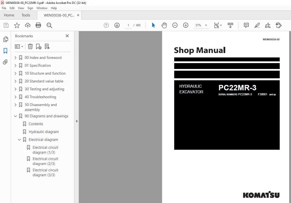
Komatsu HYDRAULIC EXCAVATOR PC22MR-3 Shop Manual WEN00038-00 – PDF DOWNLOAD
$29.95
Komatsu HYDRAULIC EXCAVATOR PC22MR-3 Shop Manual WEN00038-00 – PDF DOWNLOAD
SERIAL NUMBERS PC22MR-3 F30001 and up
Description
Komatsu HYDRAULIC EXCAVATOR PC22MR-3 Shop Manual WEN00038-00 – PDF DOWNLOAD
FILE DETAILS:
Komatsu HYDRAULIC EXCAVATOR PC22MR-3 Shop Manual WEN00038-00 – PDF DOWNLOAD
Language : English
Pages :400
Downloadable : Yes
File Type : PDF
DESCRIPTION:
Komatsu HYDRAULIC EXCAVATOR PC22MR-3 Shop Manual WEN00038-00 – PDF DOWNLOAD
SERIAL NUMBERS PC22MR-3 F30001 and up
1. General precautions
Inappropriate handling creates an extreme danger. Read and understand what is described in the Operation and Maintenance Manual before operating the machine. Read and understand what is described in this manual before starting work.
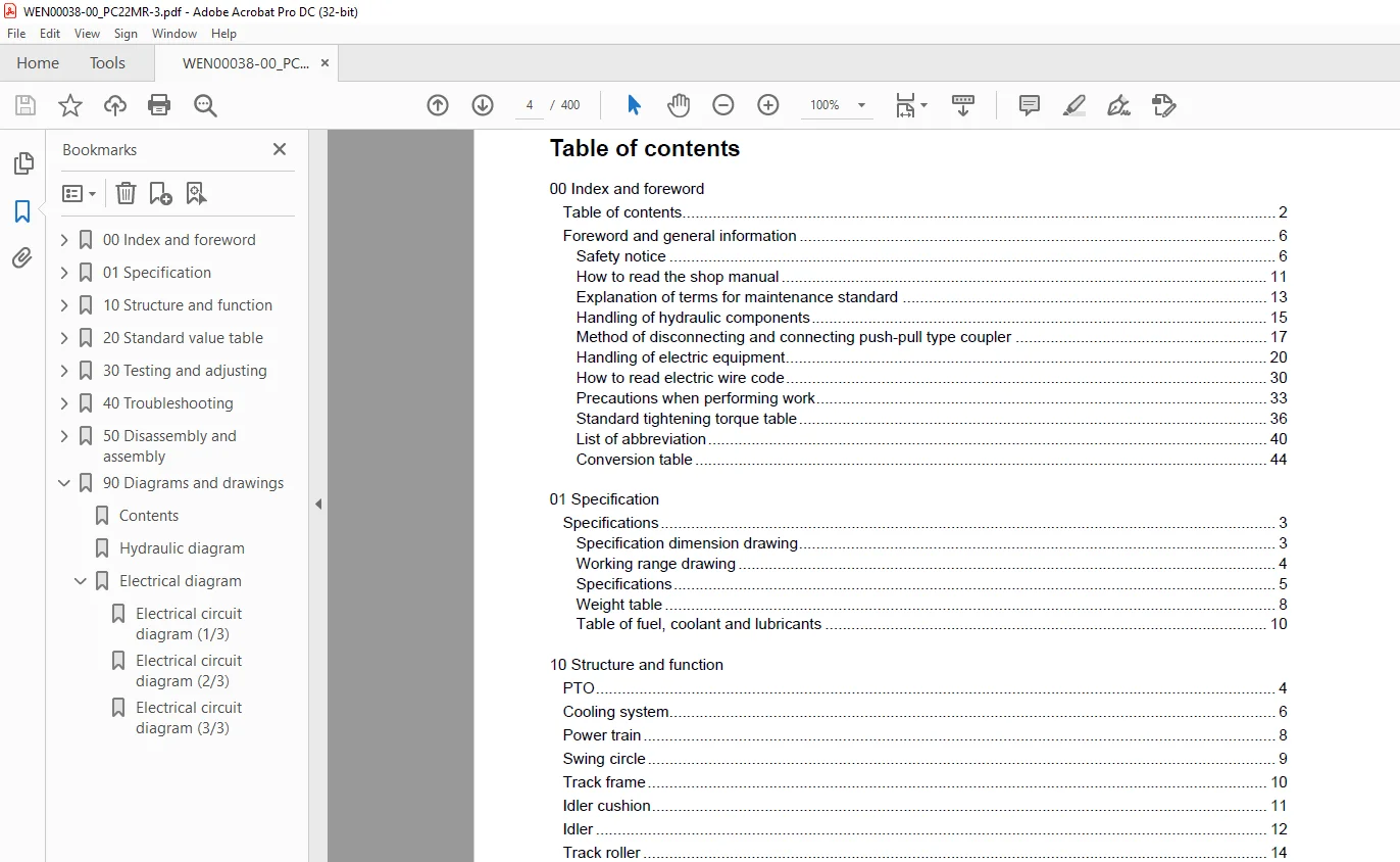
TABLE OF CONTENTS:
Komatsu HYDRAULIC EXCAVATOR PC22MR-3 Shop Manual WEN00038-00 – PDF DOWNLOAD
SERIAL NUMBERS PC22MR-3 F30001 and up
00 Index and foreword 3
Table of contents 4
Foreword and general information 8
Safety notice 8
How to read the shop manual 13
Explanation of terms for maintenance standard 15
Handling of hydraulic components 17
Method of disconnecting and connecting push-pull type coupler 19
Handling of electric equipment 22
How to read electric wire code 32
Precautions when performing work 35
Standard tightening torque table 38
List of abbreviation 42
Conversion table 46
Shop Manual 53
01 Specification 53
Contents 54
Specifications 55
Specification dimension drawing 55
Working range drawing 56
Specifications 57
Weight table 60
Table of fuel, coolant and lubricants 62
Shop Manual 63
10 Structure and function 63
Contents 64
PTO 66
Cooling system 68
Power train 70
Swing circle 71
Track frame 72
Idler cushion 73
Idler 74
Track roller 76
Sprocket 77
Track shoe 78
Rubber shoe 78
Hydraulic components layout drawing 79
Hydraulic tank and filter 80
Center swivel joint 81
Travel motor 82
Reduction gear unit 85
Hydraulic motor 86
Hydraulic valve 88
Counterbalance valve 88
Automatic 1st valve 89
Parking brake 90
Hydraulic cylinder 91
Solenoid valve 94
2nd travel speed selector solenoid valve PPC lock solenoid valve 95
Hydraulic pump 96
Model: PVK-OB-226G-PK-4220A 96
Control valve102
General view103
CLSS113
Outline of CLSS113
Operation for each function and valve116
Unload valve118
Introduction of LS pressure121
LS bypass valve122
Pressure compensation valve123
LS receiving throttle of pressure compensation valve125
LH, RH Travel junction circuit126
Self pressure reducing valve128
Swing and blade valve132
Swing holding brake cancel system134
Swing motor136
Model: PCR-1B-05A-FP-8436A136
Reduction gear unit139
Hydraulic motor140
Swing holding brake141
PPC valve146
LH PPC valves146
RH PPC valves147
Travel PPC valve148
Blade, boom swing and attachment PPC valve150
Work equipment152
Dimensions of each part of work equipment155
Arm section155
Bucket section157
Floor158
Tilt floor158
Shop Manual159
20 Standard value table159
Contents160
Standard value table161
Standard value table for engine161
Standard value table for chassis162
Performance of hydraulic pump169
Gear pump169
Piston pump169
Posture of machine for measuring performance and measurement procedure170
30 Testing and adjusting173
Contents174
List of testing, adjusting, and troubleshooting tools175
Measuring engine speed178
Adjusting valve clearance179
Measuring compression pressure180
Measuring engine oil pressure181
Testing and adjusting fuel injection timing182
Bleeding air from fuel circuit184
Testing and adjusting fan belt tension185
Adjusting fuel control lever linkage186
Measurement of clearance in swing circle bearings187
Testing and adjusting track shoe tension188
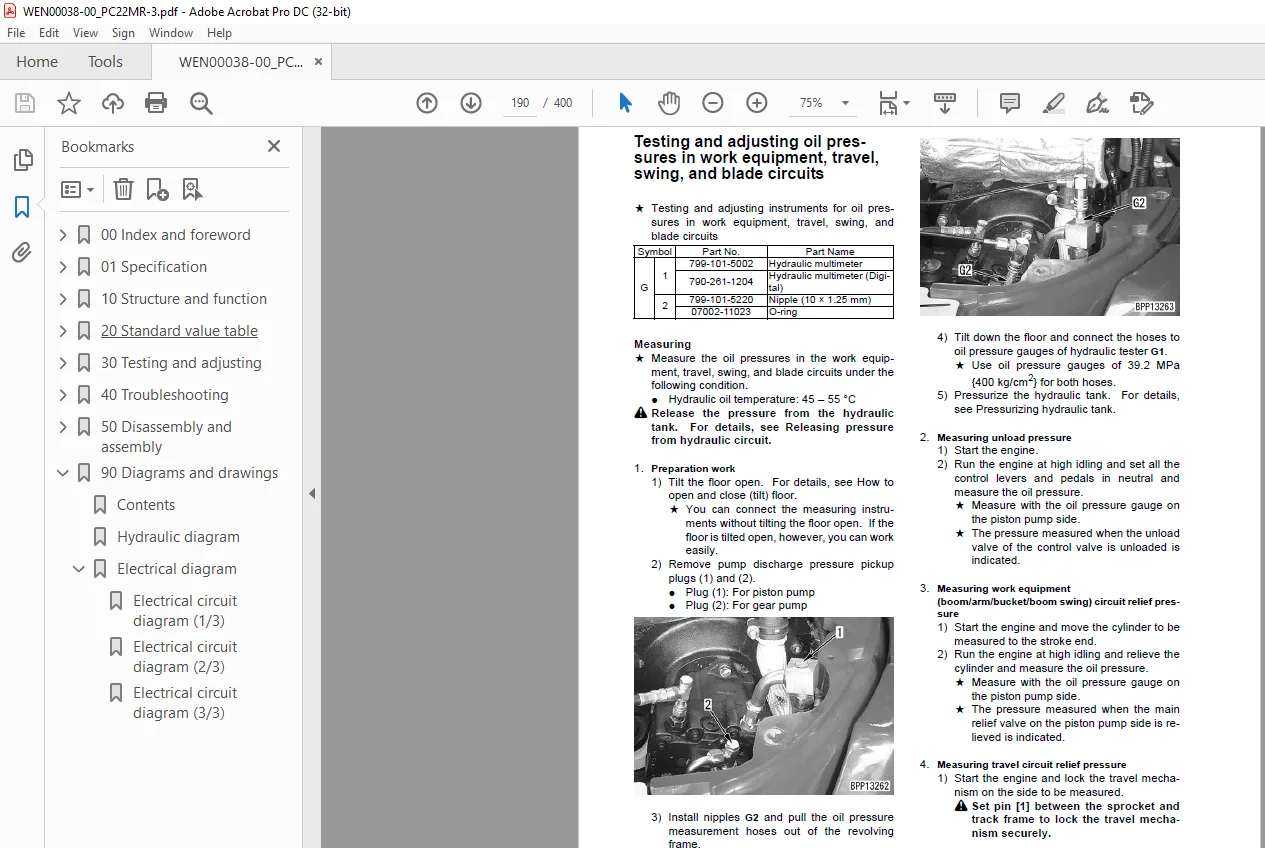
Testing and adjusting oil pressures in work equipment, travel, swing, and blade circuits190
Measuring control circuit basic pressure193
Testing and adjusting pump LS differential pressure194
Measuring solenoid valve output pressure196
Measuring PPC valve output pressure198
Measuring swing holding brake release pressure200
Measurement of oil leakage from cylinder201
Releasing residual pressure from hydraulic circuit203
Bleeding air from cylinder203
Pressurizing hydraulic tank204
How to open and close (tilt) floor205
Inspection procedures for diode208
How to start operation of KOMTRAX terminal209
Lamp display of KOMTRAX terminal213
Preparation work for troubleshooting of electrical system216
40 Troubleshooting217
Contents218
General information on troubleshooting220
Points to remember when troubleshooting220
Sequence of events in troubleshooting221
Check before troubleshooting222
Classification and troubleshooting steps223
Probable problems and troubleshooting No224
Connection table for connector pin numbers227
T- branch box and T- branch adapter table263
Troubleshooting of electrical system (E-mode)266
Before starting E-mode troubleshooting266
Information contained in troubleshooting table268
E-1 Engine does not start269
E- 2 Engine does not stop275
E- 3 When lock lever is in FREE position, whole work equipment, travel, swing, and blade systems do not work277
E- 4 When lock lever is in LOCK position, whole work equipment, travel, swing, and blade systems work280
E- 5 When machine starts traveling, travel alarm does not sound282
E- 6 When machine stops traveling, travel alarm does not stop sounding285
E- 7 Windshield wiper does not operate [Cab specification]287
E- 8 Windshield washer does not operate [Cab specification]289
E- 9 Heater does not operate291
Troubleshooting of hydraulic and mechanical system (H-mode)294
Information contained in troubleshooting table294
H- 1 Speed or power of whole work equipment, travel, swing, and blade is low295
H- 2 Engine speed lowers extremely or engine stalls298
H- 3 Whole work equipment, travel system, swing system, and blade do not work299
H- 4 Abnormal sound comes out from around hydraulic pump302
H- 5 Fine control performance or response is low302
H- 6 Speed or power of boom is low303
H- 7 Speed or power of arm is low304
H- 8 Speed or power of bucket is low305
H- 9 Speed or power of boom swing is low306
H-10 Work equipment does not move in its single operation307
H-11 Work equipment hydraulic drift is large307
H-12 Time lag of work equipment is large307
H-13 In compound operation of work equipment, speed of part loaded more is low308
H-14 Machine deviates during travel309
H-15 Travel speed or travel power is low310
H-16 Machine is not steered well or steering power is low310
H-17 Travel speed does not change311
H-18 Travel motor does not work (one side only)311
H-19 Speed or power of swing is low312
H-20 Machine does not swing313
H-21 Swing acceleration performance is low314
H-22 Machine overruns when it stops swinging315
H-23 Large shock is made when machine stops swinging315
H-24 When upper structure stops swinging, it makes large sound316
H-25 Hydraulic drift of swing is large316
H-26 Speed or power of blade is low317
H-27 Blade does not move317
H-28 Hydraulic drift of blade is large318
Troubleshooting of machine monitor system (M-mode)319
Before starting M-mode troubleshooting319
Information contained in troubleshooting table321
M- 1 When starting switch is turned ON, no monitor/gauge operates322
M- 2 When starting switch is turned ON, some monitors/gauges do not operate324
M- 3 Caution buzzer does not sound or does not stop sounding325
M- 4 While engine is running, engine oil pressure monitor flashes327
M- 5 While engine is running, charge level monitor flashes328
M- 6 Preheating system does not operate330
M- 7 Coolant temperature gauge does not indicate normally332
M- 8 Fuel level gauge does not indicate normally335
M- 9 Service meter does not operate while engine is running337
M-10Travel speed shifting system does not operate normally338
M-11 Machine monitor night lamp and working lamp do not right up341
50 Disassembly and assembly345
Contents346
How to read this manual347
Coating materials list349
Special tool list352
Removal and installation of fuel injection pump assembly354
Removal and installation of radiator and hydraulic oil cooler assembly356
Removal and installation of engine and hydraulic pump assembly358
Removal and installation of swing circle assembly360
Removal and installation of track shoe assembly361
Disassembly and assembly of idler assembly362
Disassembly and assembly of recoil spring364
Disassembly and assembly of track roller assembly367
Removal and installation of floor frame assembly368
Removal and installation of revolving frame assembly372
Disassembly and assembly of control valve assembly374
Removal and installation of center swivel joint assembly378
Disassembly and assembly of center swivel joint assembly380
Removal and installation of swing motor and swing machinery assembly382
Disassembly and assembly of hydraulic cylinder assembly383
Removal and installation of work equipment assembly387
Removal and installation of KOMTRAX station (for canopy)389
Removal and installation of KOMTRAX station (for cab)390
90 Diagrams and drawings391
Contents392
Hydraulic diagram393
Electrical diagram395
Electrical circuit diagram (1/3)395
Electrical circuit diagram (2/3)397
Electrical circuit diagram (3/3)399
IMAGES PREVIEW OF THE MANUAL:
S.M 22/12/24



