Komatsu Hydraulic Excavator PC600 -8 PC600LC-8 Shop Manual SEN00128-25 PDF
$34.95
Komatsu Hydraulic Excavator PC600 -8 PC600LC-8 Shop Manual SEN00128-25 – PDF DOWNLOAD
SERIAL NUMBERS 30001 and up
Description
Komatsu Hydraulic Excavator PC600 -8 PC600LC-8 Shop Manual SEN00128-25 – PDF DOWNLOAD
FILE DETAILS:
Komatsu Hydraulic Excavator PC600 -8 PC600LC-8 Shop Manual SEN00128-25 – PDF DOWNLOAD
Language : English
Pages :1104
Downloadable : Yes
File Type : PDF
DESCRIPTION:
Komatsu Hydraulic Excavator PC600 -8 PC600LC-8 Shop Manual SEN00128-25 – PDF DOWNLOAD
SERIAL NUMBERS 30001 and up
General precautions
Mistakes in operation are extremely dangerous. Read the Operation and Maintenance Manual carefully before operating the machine. In addition, read this manual and understand its contents before starting the work.
TABLE OF CONTENTS:
Komatsu Hydraulic Excavator PC600 -8 PC600LC-8 Shop Manual SEN00128-25 – PDF DOWNLOAD
SERIAL NUMBERS 30001 and up
Cover 1
00 Index and foreword 3
Index 3
Composition of shop manual 4
Table of contents 6
Foreword and general information 15
Safety notice 16
How to read the shop manual 21
Explanation of terms for maintenance standard 23
Handling of electric equipment and hydraulic component 25
Handling of connectors newly used for engines 34
How to read electric wire code 37
Precautions when carrying out operation 40
Method of disassembling and connecting push-pull type coupler 43
Standard tightening torque table 46
Conversion table 50
01 Specification 57
Specification and technical data 57
Specification drawings 58
Working range drawings 60
Specifications 62
Weight table 70
Table of fuel, coolant and lubricants 74
10 Structure, function and maintenance standard 77
Engine and cooling system 77
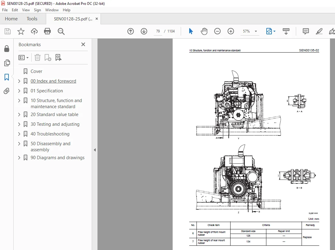
Parts related to engine 78
PTO 80
Fan, control and PTO lubrication pump 82
Radiator, oil cooler 83
Power train 85
Power train 86
Final drive 89
Sprocket 92
Swing circle 94
Swing machinery 96
Undercarriage and frame 99
Track frame, recoil spring 100
Idler 102
Carrier roller 104
Track roller 105
Track shoe 106
Hydraulic system, Part 1 113
Hydraulic system, Part 1 113
Hydraulic piping drawing 114
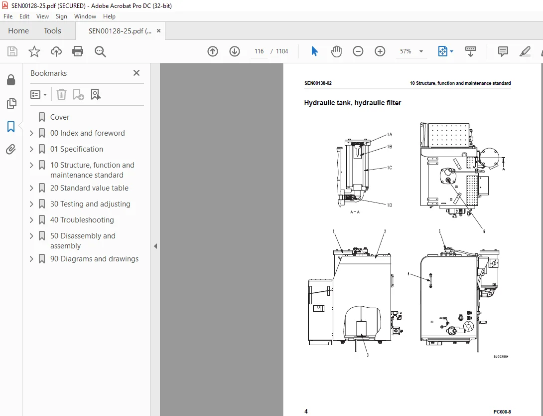
Hydraulic tank, hydraulic filter 116
Hydraulic pump (piston pump) 118
Line oil filter 146
Cooling fan pump 148
Cooling fan motor 156
Hydraulic system, Part 2 163
Control valve 164
Swing motor 183
Swing brake 186
Safety valve 187
Reverse prevention valve 189
Center swivel joint 192
Travel motor 193
Parking brake 198
Brake valve 200
Set pressures varying mechanism 203
Valve control 204
Work equipment, swing PPC valve 206
Travel PPC valve 210
Service PPC valve 212
PPC accumulator 213
PPC shuttle valve 214
Solenoid valve 215
Boom holding valve 220
Boom LOWER regeneration valve 224
Quick return valve 227
Hydraulic cylinder 230
Work equipment 235
Work equipment 236
Dimensions of work equipment 240
Cab and its attachments 245
Air conditioner piping 246
Electrical system 249
Engine control 250
Machine control system diagram 255
Monitor system 279
Sensors 294
KOMTRAX system 298
20 Standard value table 301
Standard service value table 301
Standard value table for engine 302
Standard value table for chassis 303
30 Testing and adjusting 325
Testing and adjusting, Part 1 325
Tools for testing, adjusting and troubleshooting 328
Measuring engine speed 333
Measuring intake air pressure (boost pressure) 334
Measuring exhaust gas temperature 335
Measuring exhaust gas color 336
Adjusting valve clearance 337
Measuring compression pressure 338
Measuring blow-by pressure 340
Measuring engine oil pressure 340
Testing EGR valve and bypass valve drive oil pressure 341
Handling equipment in fuel circuit 342
Releasing remaining pressure in fuel system 342
Measuring fuel pressure 343
Reduced cylinder mode operation 344
No-injection cranking 344
Testing leakage from pressure limiter and return rate from injector 345
Bleeding air from fuel circuit 347
Testing fuel system for leakage 349
Testing and adjusting alternator belt tension 350
Testing and adjusting air conditioner compressor belt tension 351
Testing clearance of swing circle bearing 352
Testing and adjusting track shoe tension 353
Testing and adjusting work equipment, swing, and travel circuit oil pressures 354
Testing and adjusting control circuit oil pressure 359
Testing and adjusting piston pump control oil pressure 361
Testing servo piston stroke 367
Measuring PPC valve output pressure 368
Measuring outlet pressures of solenoid valve and PPC shuttle valve 372
Adjusting work equipment, swing PPC valve 378
Testing and adjusting travel deviation 379
Measuring fan speed 381
Measuring fan circuit oil pressure 381
Inspection of locations of hydraulic drift of work equipment 382
Measuring oil leakage 383
Releasing remaining pressure in hydraulic circuit 387
Bleeding air from each part 388
Inspection procedures for diode 391
Testing and adjusting, Part 2 393
Special function of machine monitor 394
Handling controller voltage circuit 428
Procedure for turning on KOMTRAX terminal 429
KOMTRAX terminal lamp indications 432
Preparation work for troubleshooting electrical system 435
Adjusting mirrors 437
Pm-clinic service 438
Undercarriage inspection 444
40 Troubleshooting 447
Failure code table and fuse locations 447
Failure codes table 448
Fuse locations 452
General information on troubleshooting 455
Points to remember when troubleshooting 456
Sequence of events in troubleshooting 457
Checks before troubleshooting 458
Classification and procedures of troubleshooting 459
Information contained in troubleshooting table 460
Failure-looking phenomenon and troubleshooting No 462
Connection table for connector pin numbers 466
T- branch box and T- branch adapter table 502
Troubleshooting by failure code (Display of code), Part 1 507
Failure code [A000N1] Eng Hi Out of Std 509
Failure code [AA10NX] Aircleaner clogging 510
Failure code [AB00KE] Charge Voltage Low 512
Failure code [B@BAZG] Eng Oil Press Low 514
Failure code [B@BAZK] Eng Oil Level Low 516
Failure code [B@BCNS] Eng Water Overheat 517
Failure code [B@BCZK] Eng Water Lvl Low 518
Failure code [B@HANS] Hydr Oil Overheat 520
Failure code [CA111] ECM Critical Internal Failure 521
Failure code [CA115] Eng Ne and Bkup Speed Sens Error 522
Failure code [CA122] Chg Air Press Sensor High Error 524
Failure code [CA123] Chg Air Press Sensor Low Error 526
Failure code [CA131] Throttle Sensor High Error 528
Failure code [CA132] Throttle Sensor Low Error 530
Failure code [CA135] Eng Oil Press Sensor High Error 532
Failure code [CA141] Eng Oil Press Sensor Low Error 534
Failure code [CA144] Coolant Temp Sens High Error 536
Failure code [CA145] Coolant Temp Sens Low Error 538
Failure code [CA153] Chg Air Temp Sensor High Error 540
Failure code [CA154] Chg Air Temp Sensor Low Error 542
Failure code [CA187] Sens Supply 2 Volt Low Error 542
Failure code [CA221] Ambient Press Sens High Error 544
Failure code [CA222] Ambient Press Sens Low Error 546
Failure code [CA227] Sens Supply 2 Volt High Error 548
Failure code [CA234] Eng Overspeed 550
Failure code [CA238] Ne Speed Sens Supply Volt Error 551
Failure code [CA263] Fuel Temp Sensor High Error 552
Failure code [CA265] Fuel Temp Sensor Low Error 554
Failure code [CA271] IMV/PCV1 Short Error 555
Failure code [CA272] IMV/PCV1 Open Error 556
Failure code [CA273] PCV2 Short Error 557
Failure code [CA274] PCV2 Open Error 558
Troubleshooting by failure code (Display of code), Part 2 561
Failure code [CA322] Inj #1 (L#1) Open/Short Error 564
Failure code [CA323] Inj #5 (L#5) Open/Short Error 566
Failure code [CA324] Inj #3 (L#3) Open/Short Error 568
Failure code [CA325] Inj #6 (L#6) Open/Short Error 570
Failure code [CA331] Inj #2 (L#2) Open/Short Error 572
Failure code [CA332] Inj #4 (L#4) Open/Short Error 574
Failure code [CA342] Calibration Code Incompatibility 576
Failure code [CA351] Injectors Drive Circuit Error 577
Failure code [CA352] Sens Supply 1 Volt Low Error 579
Failure code [CA386] Sens Supply 1 Volt High Error 580
Failure code [CA441] Battery Voltage Low Error 582
Failure code [CA442] Battery Voltage High Error 582
Failure code [CA449] Rail Press Very High Error 583
Failure code [CA451] Rail Press Sensor High Error 584
Failure code [CA452] Rail Press Sensor Low Error 586
Failure code [CA553] Rail Press High Error 586
Failure code [CA554] Rail Press Sensor In Range Error 587
Failure code [CA559] Rail Press Low Error 588
Failure code [CA689] Eng Ne Speed Sensor Error 592
Failure code [CA731] Eng Bkup Speed Sens Phase Error 594
Failure code [CA757] All Persistent Data Lost Error 595
Failure code [CA778] Engine Bkup Speed Sensor Error 596
Failure code [CA1228] EGR Valve Servo Error 1 598
Failure code [CA1625] EGR Valve Servo Error 2 599
Failure code [CA1626] BP Valve Sol Current High Error 600
Failure code [CA1627] BP Valve Sol Current Low Error 602
Failure code [CA1628] Bypass Valve Servo Error 1 603
Failure code [CA1629] Bypass Valve Servo Error 2 604
Failure code [CA1631] BP Valve Pos Sens High Error 605
Failure code [CA1632] BP Valve Pos Sens Low Error 607
Failure code [CA1633] KOMNET Datalink Timeout Error 608
Failure code [CA1642] EGR Inlet Press Sens Low Error 611
Failure code [CA1653] EGR Inlet Press Sens High Error 612
Failure code [CA2185] Throt Sens Sup Volt High Error 614
Failure code [CA2186] Throt Sens Sup Volt Low Error 616
Failure code [CA2249] Rail Press Very Low Error 617
Failure code [CA2271] EGR Valve Pos Sens High Error 618
Failure code [CA2272] EGR Valve Pos Sens Low Error 620
Failure code [CA2351] EGR Valve Sol Current High Error 622
Failure code [CA2352] EGR Valve Sol Current Low Error 624
Failure code [CA2555] Grid Htr Relay Volt Low Error 625
Failure code [CA2556] Grid Htr Relay Volt High Error 626
Troubleshooting by failure code (Display of code), Part 3 629
Failure code [D110KB] Battery Relay Drive S/C 632
Failure code [D163KB] Flash Light Relay S/C 634
Failure code [D195KB] Step Light Relay S/C 636
Failure code [DA22KK] Pump Solenoid Power Low Error 638
Failure code [DA25KP] Press Sensor Power Abnormality 640
Failure code [DA2SKQ] Model Selection Abnormality 642
Failure code [DA80MA] Auto Lub Abnormal 644
Failure code [DA2RMC] Pump Comm Abnormality 646
Failure code [DAFRMC] Monitor Comm Abnormality 648
Failure code [DGE5KY] Ambi Temp Sensor S/C 650
Failure code [DGH2KB] Hydr Oil Temp Sensor S/C 651
Failure code [DHPAMA] F pump P Sensor Abnormality 652
Failure code [DHPBMA] R pump P Sensor Abnormality 654
Failure code [DV20KB] Travel Alarm S/C 656
Failure code [DW43KA] Travel Speed Sol Disc 658
Failure code [DW43KB] Travel Speed Sol S/C 660
Failure code [DW45KA] Swing Brake Sol Disc 662
Failure code [DW45KB] Swing Brake Sol S/C 664
Failure code [DW48KA] CO Cancel Sol Disc 666
Failure code [DW48KB] CO Cancel Sol S/C 668
Failure code [DW7BKA] Fan Reverse Sol Disc 670
Failure code [DW7BKB] Fan Reverse Sol S/C 671
Failure code [DW4XKA] Bucket Curl Hi Cancel Sol Disc 672
Failure code [DW4XKB] Bucket Curl Hi Cancel Sol S/C 674
Failure code [DWK0KA] 2-stage Relief Sol Disc 676
Failure code [DWK0KB] 2-stage Relief Sol S/C 678
Failure code [DX16KA] Fan Pump EPC Sol Disc 680
Failure code [DX16KB] Fan Pump EPC Sol S/C 682
Failure code [DXA0KA] TVC Sol Disc 684
Failure code [DXA0KB] TVC Sol S/C 686
Failure code [DY20KA] Wiper Working Abnormality 688
Failure code [DY20MA] Wiper Parking Abnormality 690
Failure code [DY2CKB] Washer Drive S/C 694
Failure code [DY2DKB] Wiper Drive (For) S/C 696
Failure code [DY2EKB] Wiper Drive (Rev) S/C 700
Troubleshooting of electrical system (E-mode) 703
E-1 Engine does not start (Engine does not rotate) 705
E-2 Preheater does not operate 708
E-3 Auto engine warm-up device does not work 710
E-4 Auto-decelerator does not operate 711
E-5 All work equipment, swing and travel do not move 712
E-6 Power max function does not operate 714
E-7 Machine push-up function does not operate normally 715
E-8 Any item is not displayed on machine monitor 717
E-9 Part of display on machine monitor is missing 718
E-10 Machine monitor displays contents irrelevant to the model 718
E-11 Fuel level monitor red lamp lights up while engine is running 719
E-12 Engine coolant temperature gauge does not display correctly 720
E-13 Hydraulic oil temperature gauge does not display correctly 722
E-14 Fuel gauge does not display correctly 723
E-15 Swing lock monitor does not display correctly 724
E-16 When monitor switch is operated, nothing is displayed 726
E-17 Wiper and window washer do not work 728
E-18 “Boom Raise” is not correctly displayed in monitoring function 736
E-19 “Boom Lower” is not correctly displayed in monitoring function 738
E-20 “Arm IN” is not correctly displayed in monitoring function 740
E-21 “Arm OUT” is not correctly displayed in monitoring function 741
E-22 “Bucket CURL” is not correctly displayed in monitoring function 742
E-23 “Bucket DUMP” is not correctly displayed in monitoring function 743
E-24 “Swing” is not correctly displayed in monitoring function 744
E-25 “Travel” is not correctly displayed in monitoring function 746
E-26 Air conditioner does not work 748
E-27 Step light does not light up or go off 750
E-28 Electric grease gun does not operate 754
E-29 Travel alarm does not sound or does not stop sounding 756
E-30 Horn does not sound 758
E-31 Bottom dump does not move 760
Troubleshooting of hydraulic and mechanical system (H-mode) 763
Before troubleshooting H-mode 765
Information in troubleshooting table 770
H-1 Speed or power of all work equipment, travel, and swing is low 772
H-2 Engine speed lowers remarkably or engine stalls 774
H-3 All work equipment, travel, and swing systems do not work 776
H-4 Abnormal sound is heard from around pump 778
H-5 Auto-decelerator is not reset 779
H-6 Boom speed or power is low 780
H-7 Arm speed or power is low 782
H-8 Bucket speed or power is low 783
H-9 Boom does not move 784
H-10 Arm does not move 784
H-11 Bucket does not move 785
H-12 Bottom dump does not move 785
H-13 Hydraulic drift of work equipment is large 786
H-14 Time lag of work equipment is large 787
H-15 Power max function does not operate or stop 788
H-16 Machine push-up function does not operate or stop 788
H-17 When arm and boom, bucket are operated simultaneously, boom, bucket speed is low 789
H-18 When bucket and boom, arm, swing, travel are operated simultaneously, boom, arm, swing, travel speed is low 789
H-19 When arm and swing are operated simultaneously, swing speed is low 790
H-20 Machine deviates in one direction 791
H-21 Machine deviates largely at start 793
H-22 Travel deviation is large during compound operation 794
H-23 Travel speed or power is low 795
H-24 Machine does not travel (only one track) 796
H-25 Travel speed does not change 797
H-26 Upper structure does not swing 798
H-27 Swing speed or acceleration is low 799
H-28 Upper structure overruns excessively when it stops swinging 800
H-29 Large shock is made when upper structure stops swinging 801
H-30 Large abnormal sound is made when upper structure stops swinging 802
H-31 Hydraulic drift of swing is large 803
Troubleshooting of engine (S-mode) 805
Method of using troubleshooting chart 807
S-1 Starting performance is poor 810
S-2 Engine does not start 812
S-3 Engine does not pick up smoothly 816
S-4 Engine stops during operations 817
S-5 Engine does not rotate smoothly 818
S-6 Engine lacks output (or lacks power) 819
S-7 Exhaust smoke is black (incomplete combustion) 820
S-8 Oil consumption is excessive (or exhaust smoke is blue) 821
S-9 Oil becomes contaminated quickly 822
S-10 Fuel consumption is excessive 823
S-11 Oil is in coolant (or coolant spurts back or coolant level goes down) 824
S-12 Oil pressure drops 825
S-13 Oil level rises (Entry of coolant or fuel) 826
S-14 Coolant temperature becomes too high (overheating) 828
S-15 Abnormal noise is made 829
S-16 Vibration is excessive 830
50 Disassembly and assembly 833
General information on disassembly and assembly 833
How to read this manual 834
Coating materials list 836
Special tools list 839
Sketches of special tools 845
Engine and cooling system, Part 1 853
Removal and installation of fuel supply pump assembly 854
Removal and installation of cylinder head assembly 860
Removal and installation of fuel injector assembly 877
Removal and installation of engine front seal 880
Removal and installation of engine rear seal 884
Engine and cooling system, Part 2 891
Removal and installation of engine, PTO and hydraulic pump assembly 892
Removal and installation of radiator assembly 899
Removal and installation of hydraulic oil cooler assembly 901
Removal and installation of aftercooler assembly 903
Removal and installation of fan motor assembly 905
Removal and installation of fuel tank assembly 909
Power train 911
Removal and installation of PTO assembly 912
Disassembly and assembly of PTO assembly 914
Removal and installation of swing motor and swing machinery assembly 917
Disassembly and assembly of swing machinery assembly 918
Removal and installation of swing circle assembly 925
Disassembly and assembly of final drive assembly 926
Undercarriage and frame 937
Removal and installation of track shoe assembly 938
Disassembly and assembly of 1 link in field 940
Removal and installation of idler, recoil spring assembly 944
Disassembly and assembly of idler assembly 945
Disassembly and assembly of recoil spring assembly 948
Removal and installation of track roller assembly 950
Disassembly and assembly of track roller assembly 951
Removal and installation of carrier roller assembly 954
Disassembly and assembly of carrier roller assembly 955
Removal and installation of revolving frame assembly 958
Removal and installation of counterweight assembly 960
Removal and installation of counterweight remover assembly 961
Hydraulic system 965
Removal and installation of hydraulic tank assembly 966
Removal and installation of hydraulic pump assembly 968
Removal and installation of control valve and solenoid valve assembly 971
Disassembly and assembly of control valve assembly 973
Disassembly and assembly of main control valve assembly 974
Removal and installation of swing motor assembly 978
Removal and installation of center swivel joint assembly 979
Disassembly and assembly of center swivel joint assembly 980
Disassembly and assembly of work equipment PPC valve assembly 982
Disassembly and assembly of travel PPC valve assembly 984
Disassembly and assembly of hydraulic cylinder assembly 987
Disassembly and assembly of grease gun assembly 993
Work equipment 995
Removal and installation of bucket cylinder assembly (Backhoe specification) 996
Removal and installation of bucket cylinder assembly (Loading shovel specification) 998
Removal and installation of arm cylinder assembly (Backhoe specification)1000
Removal and installation of arm cylinder assembly (Loading shovel specification)1002
Removal and installation of boom cylinder assembly (Backhoe specification)1004
Removal and installation of boom cylinder assembly (Loading shovel specification)1006
Removal and installation of bottom dump cylinder assembly (Loading shovel specification)1008
Removal and installation of bucket assembly (Backhoe specification)1009
Removal and installation of bucket assembly (Loading shovel specification)1011
Removal and installation of arm assembly (Backhoe specification)1012
Removal and installation of arm assembly (Loading shovel specification)1014
Removal and installation of boom assembly (Backhoe specification)1015
Removal and installation of boom assembly (Loading shovel specification)1017
Removal and installation of work equipment (Backhoe specification)1019
Removal and installation of work equipment (Loading shovel specification)1021
Removal and installation of anti- drop valve assembly for boom1023
Removal and installation of anti- drop valve assembly for arm1026
Disassembly and assembly anti- drop valve assembly1029
Cab and its attachments1031
Removal and installation of operator’s cab1032
Removal and installation of operator’s cab glass (stuck glass)1035
Removal and installation of front window assembly1045
Removal and installation of work equipment control lever assembly1050
Electrical system1065
Removal and installation of air conditioner unit assembly1066
Removal and installation of engine controller assembly1068
Removal and Installation of KOMTRAX terminal assembly1070
Removal and installation of pump controller assembly1070
Removal and installation of monitor assembly1071
90 Diagrams and drawings1073
Hydraulic diagrams and drawings1073
Hydraulic circuit diagram (1/4) (Backhoe specification)1075
Hydraulic circuit diagram (2/4) (ATT specification)1077
Hydraulic circuit diagram (3/4) (Loading shovel specification)1079
Hydraulic circuit diagram (4/4) (Loading shovel specification)1081
Electrical diagrams and drawings1085
Electrical circuit diagram (1/6)1087
Electrical circuit diagram (2/6)1089
Electrical circuit diagram (3/6)1091
Electrical circuit diagram (4/6)1093
Electrical circuit diagram (5/6)1095
Electrical circuit diagram (6/6)1097
Connector arrangement diagram1099
Electrical circuit diagram for air conditioner1101
IMAGES PREVIEW OF THE MANUAL:
S.M 28/12/24