Komatsu Hydraulic Excavator PC78UU-8 Shop Manual SEN05205-08 PDF
$37.95
Komatsu Hydraulic Excavator PC78UU-8 Shop Manual SEN05205-08 – PDF DOWNLOAD
SERIAL NUMBERS 15001 and up
Description
Komatsu Hydraulic Excavator PC78UU-8 Shop Manual SEN05205-08 – PDF DOWNLOAD
FILE DETAILS:
Komatsu Hydraulic Excavator PC78UU-8 Shop Manual SEN05205-08 – PDF DOWNLOAD
Language : English
Pages :1266
Downloadable : Yes
File Type : PDF
IMAGES PREVIEW OF THE MANUAL:
DESCRIPTION:
Komatsu Hydraulic Excavator PC78UU-8 Shop Manual SEN05205-08 – PDF DOWNLOAD
SERIAL NUMBERS 15001 and up
Foreword and general information
Safety notice
Important safety notice
- Proper service and repair are extremely important for safe machine operation. The service and repair techniques recommended by Komatsu and described in this manual are both effective and safe. Some of these techniques require the use of tools specially designed by Komatsu for the specific purpose. ‘
- To prevent injury to workers, the symbol k is used to mark safety precautions in this manual. The cautions accompanying these symbols should always be followed carefully. If any dangerous situation arises or may possibly arise, first consider safety, and take the necessary actions to deal with the situation.
1. General precautions
Mistakes in operation are extremely dangerous. Read the Operation and Maintenance Manual carefully before operating the machine. In addition, read this manual and understand its contents before starting the work.
TABLE OF CONTENTS:
Komatsu Hydraulic Excavator PC78UU-8 Shop Manual SEN05205-08 – PDF DOWNLOAD
SERIAL NUMBERS 15001 and up
Cover 1
Notice of revision 3
00 Index and foreword 11
Table of contents 12
Table of contents 12
Foreword and general information 22
Safety notice 22
How to read the shop manual 27
Explanation of terms for maintenance standard 29
Handling of electric equipment and hydraulic components 31
Handling of connectors newly used for engines 40
How to read electric wire code 43
Precautions when carrying out work 46
Method of disassembling and connecting push-pull type coupler 49
Standard tightening torque table 52
List of Abbreviation 56
Conversion table 60
01 Specification 65
Specification and technical data 67
Specification dimension drawings 67
Working range diagram 68
Specifications 69
Weight table 72
Table of fuel, coolant and lubricants 74
10 Structure and function 77
Engine and cooling system 79
PTO 79
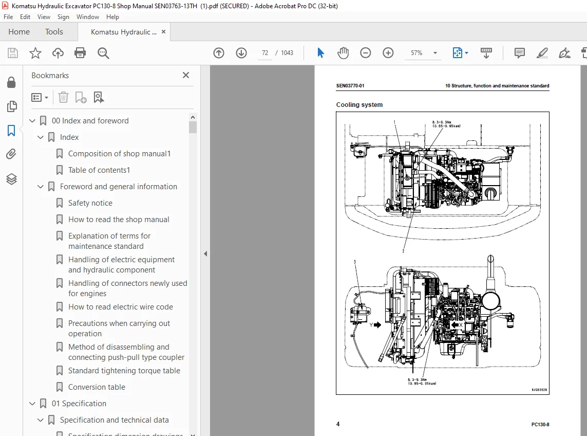
Cooling system 80
Power train system 82
Power train 82
Swing circle 84
Swing machinery 86
Undercarriage and frame 87
Track frame 87
Idler cushion 88
Hydraulic system 90
Hydraulic components layout drawing 90
Valve control 92
Hydraulic tank and filter 94
Hydraulic pump 96
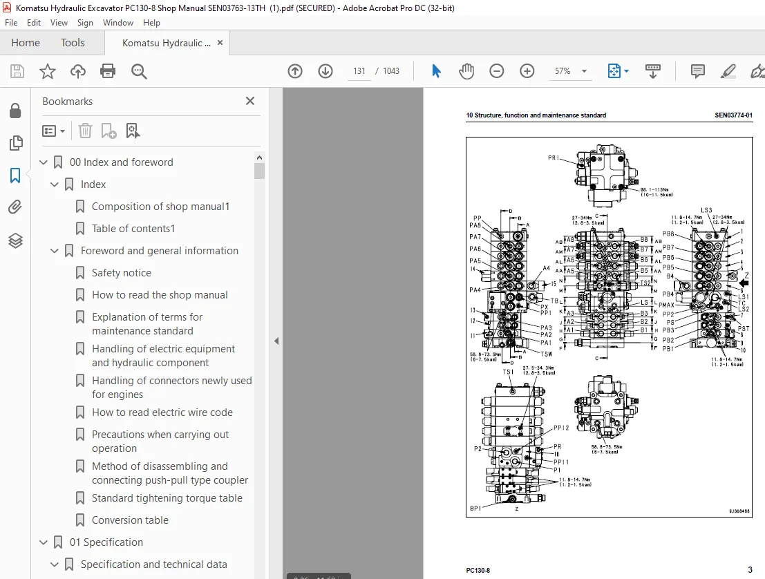
Control valve 110
CLSS 124
Functions and operation by valve 128
PPC valve 157
Swing motor 173
Travel motor 182
Center swivel joint 190
Solenoid valve 192
Accumulator 199
Multi-control valve 201
Electrical system 202
Electrical control system 202
Monitor system 251
KOMTRAX system 265
Sensors 267
20 Standard value table 275
Standard value table for engine 277
Standard value table for chassis 278
30 Testing and adjusting 289
Tools for testing, adjusting and troubleshooting 291
Tools for testing, adjusting, and troubleshooting 291
Engine and cooling systemTesting engine speed 294
Testing engine speed 294
Testing exhaust gas temperature 295
Testing exhaust gas color 296
Adjusting valve clearance 297
Testing compression pressure 299
Testing blowby pressure 301
Testing engine oil pressure 302
Handling fuel system parts 303
Releasing remaining pressure from fuel system 303
Testing fuel pressure 304
Testing fuel return rate and leakage 305
Bleeding air from fuel circuit 307
Testing fuel circuit for leakage 309
Cylinder cut-out test mode 309
No-injection cranking 310
Checking and adjusting fan belt 311
Checking and adjusting air conditioner compressor belt tension 313
Swing circle and undercarriage 314
Testing swing circle bearing clearance 314
Checking and adjusting track tension 315
Hydraulic system 317
Testing and adjusting oil pressure in work equipment and travel circuits 317
Testing and adjusting swing and blade circuit oil pressure (for the machine with blade) 320
Testing control circuit source pressure 323
Testing and adjusting oil pressure in pump PC control circuit 324
Testing LS differential pressure and adjusting LS valve 327
Testing solenoid valve output pressure 329
Testing PPC valve output pressure 333
Adjusting play of work equipment and swing PPC vavles 335
Isolating the parts causing hydraulic drift of work equipment 336
Testing and adjusting travel deviation 338
Releasing remaining pressure from hydraulic circuit 340
Testing oil leakage amount 341
Bleeding air from each part 344
Guard 347
Adjusting mirrors 347
Testing and adjusting hood catch 348
Angle adjustment of rear view camera 350
Electrical system 351
Replacement procedure of potentiometer 351
Special functions of machine monitor 352
Handling voltage circuit of engine controller 421
Preparatory work for troubleshooting of electrical system 422
Procedure for testing diodes 426
Pm Clinic service 427
Pm Clinic service 427
40 Troubleshooting 433
General information on troubleshooting 439
Points to remember when troubleshooting 439
Sequence of events in troubleshooting 440
Check before troubleshooting 441
Classification and procedures for troubleshooting 462
Failure codes table 465
Phenomena and troubleshooting numbers 469
Information in troubleshooting table 471
Troubleshooting method for disconnecting wiring harness of pressure sensor system 473
Connector list and layout 476
Connection table for connector pin numbers 485
T- branch box and T- branch adapter table 521
Fuse locations table 524
Troubleshooting by failure code 526
Failure code [989EKX] Crane Op overload 526
Failure code [989H00] Emergency Stop 526
Failure code [989HKM] Exist in Emergency Stop Area 527
Failure code [989L00] Engine Controller Lock Caution 1 527
Failure code [989M00] Engine Controller Lock Caution 2 528
Failure code [989N00] Engine Controller Lock Caution 3 528
Failure code [A000N1] Mode Eng Hi Rotation Abnormality 529
Failure code [AB00KE] Change voltage low 530
Failure code [B@BAZG] Eng oil press Low 532
Failure code [B@BCNS] Eng coolant overheat 532
Failure code [B@HANS] Hydr oil overheat 533
Failure code [CA111] ECM Critical Internal Failure 534
Failure code [CA115] Eng Ne and Bkup Speed Sens Error 536
Failure code [CA122] Chg Air Press Sensor High Error 538
Failure code [CA123] Chg Air Press Sensor Low Error 540
Failure code [CA131] Throttle Sensor High Error 542
Failure code [CA132] Throttle Sensor Low Error 544
Failure code [CA144] Coolant Temp Sens High Error 546
Failure code [CA145] Coolant Temp Sens Low Error 548
Failure code [CA153] Chg Air Temp Sensor High Error 550
Failure code [CA154] Chg Air Temp Sensor Low Error 552
Failure code [CA187] Sens Supply 2 Volt Low Error 554
Failure code [CA221] Ambient Press Sens High Error 556
Failure code [CA222] Ambient Press Sens Low Error 558
Failure code [CA227] Sens Supply 2 Volt High Error 560
Failure code [CA234] Eng Overspeed 560
Failure code [CA238] Ne Speed Sens Supply Volt Error 561
Failure code [CA271] IMV/PCV1 Short Error 562
Failure code [CA272] IMV/PCV1 Open Error 563
Failure code [CA322] Inj #1(L#1) Open/Short Error 564
Failure code [CA324] Inj #3(L#3) Open/Short Error 566
Failure code [CA331] Inj #2(L#2) Open/Short Error 568
Failure code [CA332] Inj #4(L#4) Open/Short Error 570
Failure code [CA351] Injectors Drive Circuit Error 572
Failure code [CA352] Sens Supply 1 Volt Low Error 574
Failure code [CA386] Sens Supply 1 Volt High Error 576
Failure code [CA435] Eng Oil Press Sw Error 577
Failure code [CA441] Battery Voltage Low Error 578
Failure code [CA442] Battery Voltage High Error 578
Failure code [CA449] Rail Press Very High Error 579
Failure code [CA451] Rail Press Sensor High Error 580
Failure code [CA452] Rail Press Sensor Low Error 582
Failure code [CA553] Rail Press High Error 584
Failure code [CA559] Rail Press Low Error 585
Failure code [CA689] Eng Ne Speed Sensor Error 590
Failure code [CA731] Eng Bkup Speed Sens Phase Error 592
Failure code [CA757] All Continuous Data Lost Error 593
Failure code [CA778] Eng Bkup Speed Sensor Error 594
Failure code [CA1633] KOMNET Datalink Timeout Error 597
Failure code [CA2185] Throt Sens Sup Volt High Error 598
Failure code [CA2186] Throt Sens Sup Volt Low Error 599
Failure code [CA2249] Rail Press Very Low Error 600
Failure code [CA2311] IMV Solenoid Error 601
Failure code [D197KA] Revolbing Light Relay Open Circuit 602
Failure code [D197KB] Revolbing Light Relay Short Circuit 604
Failure code [D19JKZ] Personal Code Relay Abnormality 606
Failure code [D862KA] GPS Antenna Open Circuit 608
Failure code [DA22KK] Pump Solenoid Power Low Error 610
Failure code [DA25KP] 5V Sensor1 Power Abnormality 612
Failure code [DA26KP] 5V Sensor2 Power Abnormality 614
Failure code [DA29KQ] Model Selection Abnormality 616
Failure code [DA2RMC] CAN Discon (Pump Con Detected) 618
Failure code [DAF8KB] Camera Power Supply Short Circuit 624
Failure code [DAFGMC] GPS Module Error 625
Failure code [DAFRMC] CAN Discon (Monitor Detected) 626
Failure code [DGH2KB] Hyd Oil Sensor Short 630
Failure code [DHPAMA] Pump Press Sensor Abnormality 632
Failure code [DHPCKX] Boom Bottom Pressure Sensor Abnormality 634
Failure code [DHS5KX] Travel PPC Sensor Abnormality 636
Failure code [DHSAMA] Swing RH PPC Press Sensor Abnomality 638
Failure code [DHSBMA] Swing LH PPC Press Sensor Abnomality 640
Failure code [DHX1MA] Overload Sensor Abnormality 642
Failure code [DKA0KA] Boom Angle Sensor Open Circuit 644
Failure code [DKA0KB] Boom Angle Sensor Power Short Circuit 646
Failure code [DKA0PH] Boom Angle Sensor Install Abnormality 648
Failure code [DKC0KA] Arm Angle Sensor Open Circuit 650
Failure code [DKC0KB] Arm Angle Sensor Power Short Circuit 652
Failure code [DKC0PH] Arm Angle Sensor Install Abnormality 654
Failure code [DKP0KA] Offset Angle Sensor Open Circuit 656
Failure code [DKP0KB] Offset Angle Sensor Power Short Circuit 658
Failure code [DKP0PH] Offset Angle Sensor Install Abnormality 660
Failure code [DV20KB] Travel Alarm Short Circuit 662
Failure code [DW43KA] Travel Speed Sol Open Circuit 664
Failure code [DW43KB] Travel Speed Sol Short Circuit 666
Failure code [DW45KA] Swing Brake Sol Open Circuit 668
Failure code [DW45KB] Swing Brake Sol Short Circuit 670
Failure code [DW4CKB] PPC Lock Sol Short Circuit 672
Failure code [DW4FKA] Boom Lower Stop EPC Open Circuit 674
Failure code [DW4FKB] Boom Lower Stop EPC Short Circuit 676
Failure code [DW4GKA] Boom Raise Stop EPC Open Circuit 678
Failure code [DW4GKB] Boom Raise Stop EPC Short Circuit 680
Failure code [DW4HKA] Arm Digging Stop EPC Open Circuit 682
Failure code [DW4HKB] Arm Digging Stop EPC Short Circuit 684
Failure code [DW4WKA] Cancel Bucket Dump Open Circuit 686
Failure code [DW4WKB] Cancel Bucket Dump Short Circuit 687
Failure code [DWJ0KA] Merge-divider Sol Open Circuit 688
Failure code [DWJ0KB] Merge-divider Sol Short Circuit 689
Failure code [DXA8KA] PC-EPC Sol Open Circuit 690
Failure code [DXA8KB] PC-EPC Sol Short Circuit 692
Failure code [DXE4KA] Service Current EPC Open Circuit 694
Failure code [DXE4KB] Service Current EPC Short Circuit 696
Failure code [DXEBKA] Offset Stop EPC Open Circuit 698
Failure code [DXEBKB] Offset Sopt EPC Short Circuit 700
Failure code [DY20KA] Wiper Working Abnormality 702
Failure code [DY20MA] Wiper Parking Abnormality 704
Failure code [DY2CKA] Washer Drive Open Circuit 706
Failure code [DY2CKB] Washer Drive Short Circuit 708
Failure code [DY2DKB] Wiper Drive (Fwd) Short Circuit 710
Failure code [DY2EKB] Wiper Drive (Rev) Short Circuit 712
Troubleshooting of electrical system (E-mode) 715
E-1 When starting switch turned ON, machine monitor displays nothing 715
E-2 Engine does not start (Engine does not turn) 718
E-3 Preheater does not operate 722
E-4 Automatic warm-up system does not work (in cold weather) 724
E-5 All work equipment, swing, and travel mechanism do not move or cannot be locked 725
E-6 Precaution lights up while engine is running 730
E-7 Emergency stop lamp lights up while engine is running 731
E-8 Engine coolant temperature gauge does not indicate normally 732
E-9 Hydraulic oil temperature gauge does not display normally 734
E-10 Fuel level gauge does not display normally 738
E-11 Contents of display by machine monitor are different from applicable machine 740
E-12 Machine monitor does not display partially 740
E-13 Function switch does not work 740
E-14 Auto-decelerator does not work normally 741
E-15 Working mode does not change 742
E-16 Travel speed does not change 743
E-17 Alarm buzzer cannot be stopped 744
E-18 Windshield wiper and window washer do not operate 746
E-19 Swing holding brake does not operate normally 750
E-20 Travel alarm does not sound or does not stop sounding 752
E-21 While starting switch is in OFF position, service meter is not displayed 753
E-22 Machine monitor cannot be set in service mode 753
E-23 Monitoring function does not display lever operation signals normally 754
E-24 Automatic stop function for boom RAISE operation does not work normally and boom interferes (cab side) 774
E-25 Automatic stop function for arm IN operation does not work normally and arm interferes (cab side) 775
E-26 Automatic stop function for offset LEFT operation does not work normally and work equipment interferes (cab side) 776
E-27 Automatic stop function for boom LOWER operation does not work normally and boom interferes (right exterior side) 777
E-28 Automatic stop function for arm IN operation does not work normally and arm interferes (right exterior side) 778
E-29 Automatic stop function for offset RIGHT operation does not work normally and work equipment interferes (right exterior side) 779
E-30 Work equipment stop distance is too far or too near 780
E-31 Boom RAISE end cushion does not work at all or works insufficiently 782
E-32 Arm IN end cushion does not work at all or works insufficiently 783
E-33 Work equipment stops after or before height limit 784
E-34 Depth indication is displayed inaccurately or is not displayed at all 786
E-35 While work equipment emergency operation switch is not turned to ON position, buzzer sounds for seven seconds 788
E-36 When work equipment emergency operation switch is turned to ON position, work equipment emergency operation monitor does not light up 789
E-37 KOMTRAX system does not operate normally 790
Troubleshooting of hydraulic and mechanical system (H-mode) 791
Information in troubleshooting table 791
System chart for hydraulic and mechanical systems 792
Failure mode and cause table 794
H-1 Speed or power of all work equipment, swing, and travel are low 796
H-2 Engine speed lowers significantly or engine stalls 797
H-3 No work equipment, travel and swing move 798
H-4 Abnormal sound comes out from around hydraulic pump 799
H-5 Fine control performance or response of work equipment and travel is low 800
H-6 Speed or power of boom is low 801
H-7 Speed or power of arm is low 802
H-8 Speed or power of bucket is low 803
H-9 Blade or power is low 804
H-10 Speed or power of offset is low 805
H-11 Work equipment does not move singly 806
H-12 Hydraulic drift of work equipment is large 807
H-13 Time lag of work equipment is large 809
H-14 In compound operation of work equipment, speed of part loaded more is low 810
H-15 When machine swings and boom is raised simultaneously, boom rising speed goes down 811
H-16 Travel speed goes down largely during simultaneous compound operation of work equipment swing and travel 812
H-17 Machine deviates during travel 813
H-18 Travel speed is low 814
H-19 Machine is not steered well or steering power is low 815
H-20 Travel speed does not change, or travel speed is low/high 816
H-21 Travel system does not move (only one side) 817
H-22 Upper structure does not swing 818
H-23 Swing acceleration or swing speed is low, and swing power is low 819
H-24 Upper structure overruns remarkably when it stops swinging 821
H-25 Large shock is made when upper structure stops swinging 822
H-26 Loud abnormal is heard when upper structure stops swinging 823
H-27 Hydraulic drift of swing is large 824
H-28 Oil flow in attachment circuit cannot be controlled 825
H-29 Boom RAISE, arm IN, and the left offset lever do not stop automatically and interfere with each other 826
Troubleshooting of engine (S-mode) 828
Method of using troubleshooting chart 828
S-1 Starting performance is poor 832
S-2 Engine does not start 833
S-3 Engine does not pick up smoothly 836
S-4 Engine stops during operations 837
S-5 Engine does not rotate smoothly 838
S-6 Engine lacks output (or lacks power) 839
S-7 Exhaust smoke is black (incomplete combustion) 840
S-8 Oil consumption is excessive (or exhaust smoke is blue) 841
S-9 Oil becomes contaminated quickly 842
S-10 Fuel consumption is excessive 843
S-11 Oil is in coolant (or coolant spurts back or coolant level goes down) 844
S-12 Oil pressure drops 845
S-13 Oil level rises (Entry of coolant or fuel) 846
S-14 Coolant temperature becomes too high (overheating) 847
S-15 Abnormal noise is made 848
S-16 Vibration is excessive 849
50 Disassembly and assembly 851
General information on disassembly and assembly 854
How to read this manual 854
Coating materials list 856
Special tools list 859
Sketches of special tools 863
Engine and cooling system 868
Removal and installation of fuel supply pump assembly 868
Removal and installation of fuel injector assembly 872
Removal and installation of cylinder head assembly 876
Removal and installation of radiator assembly 887
Removal and installation of aftercooler assembly 890
Removal and installation of oil cooler assembly 892
Removal and installation of engine front seal 896
Removal and installation of engine rear seal 898
Removal and installation of engine and hydraulic pump assembly 902
Removal and installation of engine hood assembly 913
Removal and installation of fuel tank assembly 914
Power train 917
Removal and installation of travel motor and final drive assembly 917
Disassembly and assembly of travel motor and final drive assembly 919
Removal and installation of swing motor and swing machinery assembly 957
Disassembly and assembly of swing machinery assembly 959
Removal and installation of swing circle assembly 966
Undercarriage and frame 968
Disassembly and assembly of track roller assembly 968
Disassembly and assembly of idler assembly 972
Disassembly and assembly of recoil spring assembly 975
Separation and connection of track shoe assembly 977
Removal and installation of sprocket 979
Removal and installation of revolving frame assembly 980
Removal and installation of counterweight assembly 983
Hydraulic system 986
Removal and installation of conter swivel joint assembly 986
Disassembly and assembly of center swivel joint assembly 988
Removal and installation of hydraulic tank assembly 990
Removal and installation of hydraulic pump assembly 993
Removal and installation of control valve assembly 997
Disassembly and assembly of control valve assembly1004
Disassembly and assembly of work equipment PPC valve assembly1009
Disassembly and assembly of travel PPC valve assembly1011
Disassembly and assembly of hydraulic cylinder assembly1013
Work equipment1018
Removal and installation of work equipment assembly1018
Removal and installation of 1st boom assembly1023
Removal and installation of 2nd boom assembly1028
Removal and installation of offset bracket assembly1031
Removal and installation of blade assembly1035
Cab and its attachments1037
Removal and installation of operator’s cab assembly1037
Removal and installation of operator cab glass (adhered window glass)1043
Removal and installation of front window assembly1053
Removal and installation of floor frame assembly1054
Removal and installation of air conditioner unit assembly1061
Removal and installation of air conditioner compressor assembly1067
Removal and installation of machine monitor assembly1069
Removal and installation of workequipment control lever assembly1071
Electrical system1083
Removal and installation of engine controller assembly1083
Removal and installation of pump controller assemby1085
Removal and installation of air conditioner controller assembly1086
Removal and installation of KOMTRAX terminal assembly1087
60 Maintenance standard1089
Engine and cooling system1091
Engine mount1091
PTO1092
Cooling system1093
Power train system1096
Swing circle1096
Swing machinery1098
Undercarriage and frame1099
Track frame1099
Idler cushion1100
Idler1101
Carrier roller1102
Track roller1103
Sprocket1104
Track shoe1106
Hydraulic system1111
Hydraulic tank and filter1111
Hydraulic pump1112
Control valve1115
PPC valve1129
Swing motor1141
Travel motor1144
Center swivel joint1145
Solenoid valve1146
Accumulator1147
Work equipment1148
Work equipment1148
Dimensions of components1150
Work equipment cylinder1154
80 Air conditioner1157
Air Conditioner1159
Caution about refrigerant1159
Air conditioner component1160
Configuration and function of refrigeration cycle1162
Outline of refrigeration cycle1163
Air conditioner unit1166
Air conditioner controller1171
Compressor1172
Condenser1173
Receiver drier1174
Sensor1175
Procedure for testing and troubleshooting1176
Circuit diagram and arrangement of connector pins1178
System diagram1180
Detail of air conditioner unit1182
Part and connector locations1184
Testing air leakage (duct)1188
Testing with self-diagnosis function1189
Testing vent (mode) changeover1193
Testing Recirc/Fresh air changeover1194
Testing inner sensor1195
Testing outer sensor1196
Testing sunlight sensor1197
Testing (dual) pressure switch for refrigerant1198
Testing relays1199
Troubleshooting chart 11200
Troubleshooting chart 21202
Information in troubleshooting table1204
Troubleshooting for power supply and CAN communication system (Air conditioner does not operate)1205
Troubleshooting for compressor and refrigerant system (Air is not cooled)1209
Troubleshooting for blower motor system (No air comes out orair flow is abnormal)1212
Troubleshooting for temperature control1214
Troubleshooting for vent (mode) changeover1216
Troubleshooting for Recirc/Fresh air changeover1218
Troubleshooting for temperature sensor system1220
Troubleshooting with gauge pressure1222
Connection of service tool1224
Precautions for disconnecting and connecting air conditioner piping1226
Handling of compressor oil1228
90 Diagrams and drawings1231
Hydraulic diagrams and drawings1233
Symbols used in hydraulic circuit diagrams1233
Hydraulic circuit diagram1235
Actuator attachment hydraulic circuit diagram1237
Electrical diagrams and drawings1241
Symbols used in electric circuit diagrams1241
Electrical circuit diagram1245
Air conditioner electrical circuit diagram1257
Index1259
S.M 29/12/24