
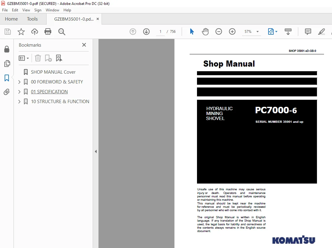
Komatsu HYDRAULIC MINING SHOVEL PC7000-6 Shop Manual 35001-xD-GB-0 PDF
$33.95
Komatsu HYDRAULIC MINING SHOVEL PC7000-6 Shop Manual 35001-xD-GB-0 – PDF DOWNLOAD
Serial Number 06208 and up
Description
Komatsu HYDRAULIC MINING SHOVEL PC7000-6 Shop Manual 35001-xD-GB-0 – PDF DOWNLOAD
FILE DETAILS:
Komatsu HYDRAULIC MINING SHOVEL PC7000-6 Shop Manual 35001-xD-GB-0 – PDF DOWNLOAD
Language : English
Pages :1397
Downloadable : Yes
File Type : PDF
DESCRIPTION:
Komatsu HYDRAULIC MINING SHOVEL PC7000-6 Shop Manual 35001-xD-GB-0 – PDF DOWNLOAD
Serial Number 06208 and up
SAFETY INFORMATION
To enable you to use this machine safely, and to prevent injury to operators, service personnel or bystanders, the precautions and warnings included in this manual and the safety signs attached to the machine must always be followed. To identify important safety messages in the manual and on the machine labels, the following signal words are used. The “Safety Alert Symbol” identifies important safety messages on machines, in manuals, and elsewhere. When you see this symbol, be alert to the risk of personal injury or death. Follow the instructions in the safety message
TABLE OF CONTENTS:
Komatsu HYDRAULIC MINING SHOVEL PC7000-6 Shop Manual 35001-xD-GB-0 – PDF DOWNLOAD
Serial Number 06208 and up
SHOP MANUAL Cover 1
00 FOREWORD & SAFETY 3
1 Foreword 5
11 Before reading this manual 6
12 Contents of this binder 7
121 Contacting the Service 7
122 Guarantee 7
13 Division of the binder 8
2 SAFETY 9
21 SAFETY INFORMATION 10
22 OVERVIEW 11
221 NORMAL OPERATIONS 11
222 REGULAR MAINTENANCE 11
223 TROUBLESHOOTING, ADJUSTMENTS AND REPAIR 11
224 ADDITIONAL SAFETY PRECAUTIONS FOR ASSEMBLING, DISASSEMBLING AND TRANSPORTATION OF THE EXCAVATOR 11
23 SOUND PRESSURE AND VIBRATION LEVELs IN THE OPERATOR’S CAB 12
231 SOUND 12
232 VIBRATION 12
24 GENERAL PRECAUTIONS COMMON TO OPERATION ON THE EXCAVATOR 13
241 UNDERSTANDING THE MACHINE 13
242 PRECAUTIONS BEFORE STARTING OPERATION ON THE EXCAVATOR 13
2421 ENSURING SAFE OPERATION 13
243 PREPARATIONS FOR SAFE OPERATION 13
2431 PRECAUTIONS REGARDING SAFETY RELATED EQUIPMENT 13
2432 INSPECTING THE MACHINE 13
2433 WEAR WELL FITTING CLOTHES AND PROTECTIVE EQUIPMENT 14
2434 KEEP MACHINE CLEAN 14
2435 PRECAUTIONS INSIDE OPERATOR’S COMPARTMENT 14
2436 PROVIDE FIRE EXTINGUISHER AND FIRST AID KIT 15
2437 IF A PROBLEM IS FOUND 15
244 FIRE PREVENTION 15
2441 PRECAUTIONS TO PREVENT FIRE 15
2442 ACTION IF FIRE OCCURS 17
2443 EMERGENCY EXIT FROM OPERATOR’S CAB 17
245 PRECAUTIONS WHEN GETTING ON OR OFF THE MACHINE 18
2451 USE HANDRAILS AND STEPS WHEN GETTING ON OR OFF THE MACHINE 18
2452 NO JUMPING ON OR OFF THE MACHINE 18
2453 NO PEOPLE ON THE ATTACHMENT 18
2454 WORKING IN HIGH PLACES 18
2455 LEAVING OPERATOR’S SEAT WITH LOCK 19
2456 LEAVING THE MACHINE 19
246 BURN PREVENTION 19
2461 Hot coolant 19
2462 Hot oil 20
247 PRECAUTIONS WHEN CLEANING CAB GLASS 20
248 PRECAUTIONS RELATED TO PROTECTIVE STRUCTURES 20
2481 UNAUTHORIZED MODIFICATION 21
2482 PRECAUTIONS RELATED TO ATTACHMENTS AND OPTIONS 21
249 ELECTROMAGNETIC COMPATIBILITY (EMC) 21
2410 PRECAUTIONS AT JOBSITE 22
24101 VISIBILITY FROM OPERATOR’S SEAT 23
24102 CAMERA SYSTEM WITH MONITORS 23
24103 ENSURE GOOD VISIBILITY 23
24104 CHECKING SIGNS AND SIGNALMAN’S SIGNALS 23
24105 INVESTIGATE AND CONFIRM JOBSITE CONDITIONS 24
24106 DO NOT GO CLOSE TO HIGH VOLTAGE CABLES 24
24107 WORKING ON LOOSE GROUND 25
24108 GAS, DUST, STEAM AND SMOKE 25
24109 VENTILATION OF ENCLOSED AREAS 26
2411 STARTING motor 27
24111 WARNING TAG 27
24112 CHECKS BEFORE STARTING motor 27
24113 PRECAUTION WHEN STARTING motor 27
24114 PRECAUTION IN COLD AREAS 28
2412 OPERATION 28
24121 CHECKS BEFORE OPERATION 28
24122 PRECAUTIONS WHEN TRAVELLING IN FORWARD OR REVERSE 29
24123 PRECAUTIONS WHEN travelling 30
24124 TRAVELLING ON SLOPES 31
24125 OPERATIONS ON SLOPES 32
24126 PROHIBITED OPERATIONS 32
24127 TRAVELLING ON FROZEN OR SNOW COVERED SURFACES 33
24128 PARKING THE MACHINE 33
24129 TRANSPORTATION 33
25 PRECAUTION FOR MAINTENANCE 34
251 GENERAL PRECAUTIONS 34
2511 SELECTION AND QUALIFICATION OF PERSONNEL – BASIC RESPONSIBILITIES 35
2512 STOP motor FOR MAINTENANCE 36
2513 WARNING TAG 37
2514 KEEP WORKPLACE CLEAN AND TIDY 38
2515 APPOINT LEADER WHEN WORKING WITH OTHERS 38
2516 TWO WORKERS FOR MAINTENANCE WHEN THE MACHINE IS RUNNING 39
2517 INSTALLING, REMOVING OR STORING ATTACHMENTS 39
2518 PRECAUTIONS WHEN WORKING UNDER THE MACHINE OR EQUIPMENT 40
2519 NOISE 40
25110 WHEN USING A HAMMER 40
25111 PROPER TOOLS 41
25112 ACCUMULATOR 41
25113 PERSONNEL 41
252 PRECAUTIONS FOR INSPECTION AND MAINTENANCE 42
2521 PRECAUTION WHEN WELDING 42
2522 BATTERY HANDLING 42
253 PRECAUTIONS WITH HIGH PRESSURE FLUID 43
2531 PRECAUTIONS WITH HIGH FUEL PRESSURE 43
2532 HANDLING HIGH PRESSURES HOSES OR PIPES 44
2533 REPLACEMENT OF HOSE LINES 44
2534 INSPECTION OF HOSE LINES 44
2535 PERIODIC REPLACEMENT OF SAFETY CRITICAL PARTS 45
2536 PRECAUTIONS FOR HIGH VOLTAGE 45
2537 AIR CONDITIONING MAINTENANCE 45
2538 COMPRESSED AIR 46
2539 WASTE MATERIALS 46
26 ADDITIONAL SAFETY INFORMATION FOR TROUBLESHOOTING AND ADJUSTMENTS 47
261 INSPECTION OF THE HYDRAULIC SYSTEM 47
262 TWO WORKERS ONLY WHEN THE MACHINE IS RUNNING DURING ADJUSTMENTS 47
263 AREAS OF POTENTIAL DANGER AROUND THE EXCAVATOR 47
27 SPECIAL SAFETY EQUIPMENT 48
271 FRONT GUARD PROTECTIVE STRUCTUR ’FOPS’ FOR OPERATOR’S CAB 49
272 OBJECT HANDLING 49
273 LIGHTING 49
274 WARNING BEACON 49
275 SAFETY HARNESS IN CONFORMITY WITH EN 361 (EUROPEAN STANDARD) 49
2751 SAFETY HARNESS IN CONFORMITY WITH EN 361 (EUROPEAN STANDARD) 49
2752 INSTRUCTIONS FOR USE 51
2753 PRIOR TO USING THE HARNESS (1), THE WEARER SHALL 53
2754 RECOMMENDATIONS FOR USE OF THE HOLDING HOOKS AND HOLD- BACK HOOKS OF THE SAFETY HARNESS 53
2755 INSTRUCTIONS FOR USE 55
01 SPECIFICATION 57
PC7000-6 59
10 STRUCTURE & FUNCTION 67
TOC 69
1 Introduction 81
11 Foreword 82
12 Recommendations for environmentally friendly operation and maintenance of hydraulic mining shovels 83
13 Explanation of abbreviations 84
14 Diagrams and illustrations in this manual 85
2 Specifications 87
21 Lifting Gears 88
22 Safety hints for sling accessory 90
23 Standard Tightening Torque Chart 91
24 Conversion Table 92
25 Blind plugs 98
26 Classification of threads to the nominal width100
27 Plugs and fittings according to ISO 8434-1 / DIN 2353101
3 Main assembly groups103
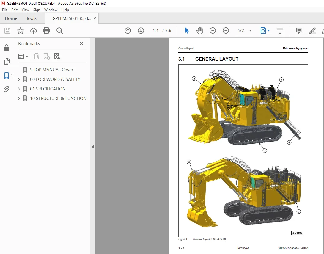
31 General layout104
32 Superstructure106
321 Superstructure side view106
322 Superstructure top view108
33 Machine house110
34 Hydraulic oil tank112
35 Hydraulic oil cooler114
36 Fuel tank116
37 Cab support118
38 Operator’s cab120
39 Main control blocks (FSA)122
310 Slew gear124
3101 Slew gear L&S124
3102 Slew gear (SIEBENHAAR)126
311 Undercarriage128
312 Slew ring130
313 Attachment132
3131 Front Shovel Attachment (FSA)132
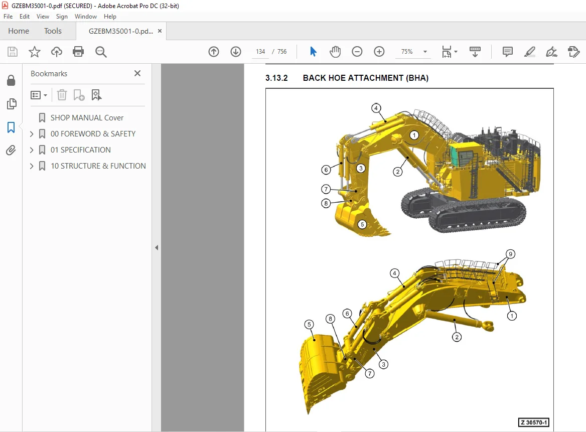
3132 Back hoe Attachment (BHA)134
4 Drive137
41 Prime drive assembly138
42 Engine and PTO mounts140
421 Engine Mounts140
422 Checks and adjustments141
423 Torque Support141
43 Flexible coupling142
44 Fan drive and radiator assembly144
441 Radiator assembly144
442 Fan motor146
443 Expansion tanks147
444 Radiator fan drive148
4441 Flow chart of radiator fan control150
4442 Hydraulic schematic of radiator fan drive151
445 Fan pump type HPV190152
446 Radiator fan speed testing & adjustment154
4461 Testing & readjustment procedure156
4462 Basic adjustment procedure157
45 Pump distributor gearbox (PTO)158
451 PTO oil filling, oil level, and ventilation160
452 Pump spline lubrication162
4521 Oil level in the main pump & gear oil pump drive shaft housing163
453 PTO lubrication and cooling164
4531 Hydraulic components and schematic of cooling circuit-1164
4532 Schematic overview – PTO gear oil cooling circuit-1166
4533 Checks and adjustments168
46 Hydraulic pumps – location, drive speed and flow rates170
47 Air cleaner174
5 Hydraulic oil tank177
51 General layout178
52 Hydraulic oil tank, location of the electric equipment180
53 Suction oil tank with strainers182
54 Return oil collector pipe with strainer184
55 Back pressure valve186
56 Transfer pump188
57 Return and leak oil filter190
58 Breather filter192
6 Hydraulic oil cooling195
61 Overall view of the hydraulic oil cooling196
62 Function of the hydraulic oil cooling circuit198
63 Adjustment of the back pressure valve200
64 Stepless cooler fan RPM control202
641 Pressure limiting valves204
642 Components of the fan drive circuits206
643 Fan pump type HPV190208
65 Oil cooler fan speed testing/adjustment210
651 Testing & readjustment procedure212
652 Basic adjustment procedure213
7 Controlling215
71 General layout216
72 Control and filter panels – location of components218
721 Control and filter panel engine 1 (rear)218
722 Valve cartridge block engine 1 (rear)220
723 Control and filter panel engine 2 (front)222
73 Pilot pressure supply and adjustments224
731 Pilot pressure control (PPC) circuit224
732 Pilot pressure operating the main block spools226
733 Checks and adjustment of pilot pressure228
734 Remote control valves arrangement230
74 Function of the electro hydraulic control system232
741 Exemplary illustration of the joystick signal flow234
75 Hand lever (joystick) control236
751 Voltage supply of hand lever 20S020237
752 Direction signal course from hand lever to controllers238
753 Double ratiometric* output diagram239
76 Foot pedal control240
761 Voltage supply of foot lever 20S021a242
762 Direction signal course from foot pedal to controllers243
763 Double ratiometric* output diagram for 2 direction pedal244
764 Single ratiometric* output diagram for 1 direction pedal245
77 Hand lever & foot pedal monitoring246
771 Lever monitoring screens (exemplary)248
772 Valve monitoring screen (exemplary)250
78 Valve solenoid adjustment252
781 Overview sol min/max current & adjustment range253
79 ACCEL & DECEL time adjustment254
791 Accel & Decel times254
8 Components257
81 Main control blocks and high pressure screens (FSA)258
82 Main control blocks with valves (FSA)260
83 Main control blocks with valves (BHA)262
84 Distributor manifold – location of restrictor blocks and anti cavitation valves (FSA)264
85 Distributor manifold – location of restrictor blocks and anti cavitation valves (BHA)266
86 Restrictor block with secondary relief valve268
87 Anti-cavitation valve (ACV) block270
871 Single ACV block on the manifold270
872 Double ACV block on the manifold272
88 Remote control valves274
89 4/3 Directional solenoid valves276
810 Proportional solenoid valves278
811 High-pressure screen280
812 Control blocks and valves282
8121 Main control blocks I, II, II (4 spool blocks)282
8122 Hydraulic diagram of a 4-spool valve block284
8123 Spool types285
8124 Spool positions (control block)288
8125 MRV, SRV, and ACV290
8126 Load holding valve292
8127 Main control block IV (slew)294
813 Travel brake valve296
814 Pressure reducing valve298
815 4/2 Directional valves300
816 Pressure double stage valve302
817 Hydraulic cylinder304
8171 Cylinder data markings306
9 Main hydraulic pumps, pump regulation, valve control & monitoring system307
91 General308
911 Pump data310
92 Main pumps313
921 Hydraulic pump type HPV375+375313
9211 Main pump sectional drawings316
922 Servo valve318
9221 VC valve servo piston319
923 EPC valve324
93 Electronic pump regulation system326
931 Cut-off function328
932 Slew control329
933 Altitude pump displacement329
934 Temperature control329
9341 Hydraulic oil temperature charts330
9342 PTO gear oil temperature charts330
935 Pump flow control331
936 Stepless oil cooler fan speed control332
937 Diagnostics and monitoring332
94 Pump & valve controllers334
95 Multimonitor336
951 Service menu screen339
96 Service menu – 01 Monitoring339
961 Monitoring PUMP 1 controller340
962 Monitoring PUMP 2 controller341
963 Monitoring VALVE 0 controller342
964 Monitoring VALVE 1 controller344
965 Monitoring VALVE 2 controller345
966 Monitoring all controllers345
97 Using Multimonitor functions for monitoring346
971 Hold function346
98 Service menu – 02 Abnormality Record347
981 To delete any failure record from the display348
982 Troubleshooting procedures348
983 Failure codes on the Multimonitor349
99 Service menu – 03 Default356
910 Service menu – 04 Adjustment357
9101 Adjustments for PUMP 1 controller357
9102 Adjustments for PUMP 2 controller359
9103 Adjustments for VALVE 0 controller360
9104 Adjustments for VALVE 2 controller361
9105 Details on the adjustable parameters362
91051 PUMP 1 controller362
91052 PUMP 2 controller363
91053 VALVE 0 controller365
91054 VALVE 2 controller367
9106 Description of the Primary P-Factor368
9107 Pump16F/R Solenoid Min Current Adjustment369
9108 Pump16F/R Solenoid Max Current Adjustment370
9109 Accel & Decel times371
911 Service menu – 05 Display Setup372
912 Checks and adjustments374
9121 Engine power check374
9122 Cut-off function check376
91221 Cut-off for clam close (FSA only)377
913 Engine speed sensors (pick-up)378
9131 General379
9132 Engine speed sensor (pick-up) adjustment379
10 Operating hydraulics381
101 General382
1011 Allocation of pumps and main valve blocks384
102 Spool functions (FSA)386
1021 Floating function for boom and stick cylinders386
1022 Spool functions (BHA)388
103 Hydraulics for the attachment cylinders390
1031 Electric / hydraulic flowchart “Boom UP” (FSA)390
1032 Electric / hydraulic flowchart “boom up” (BHA)392
1033 Electric / hydraulic flowchart “boom down” (FSA), single movement and Auto-float ON394
1034 Electric / hydraulic flowchart “boom down” (FSA), Auto-float OFF – button 20S095 pressed and single movement396
1035 Electric / hydraulic flowchart “Boom down” (BHA)398
1036 Electric / hydraulic flowchart “Stick out” (FSA)400
1037 Electric / hydraulic flowchart “Stick out” (BHA)402
1038 Electric / hydraulic flowchart “Stick in” (FSA), Auto-float ON and single movement404
1039 Electric / hydraulic flowchart “Stick in” (FSA), Auto-float OFF- 20S098 pressed & single movement406
10310 Electric / hydraulic flowchart “Stick in” (BHA)408
10311 Electric / hydraulic flowchart “Bucket fill” (FSA)410
10312 Electric / hydraulic flowchart “Bucket fill” (BHA)412
10313 Electric / hydraulic flowchart “Bucket dump” (FSA)414
10314 Electric / hydraulic flowchart “Bucket dump” (BHA)416
10315 Electric / hydraulic flowchart “Clam open” (FSA)418
10316 Electric / hydraulic flowchart “Clam close” (FSA)420
10317 Checks and adjustments of the main relief valve (MRV)422
10318 Checks and adjustments of the secondary relief valves (SRV)424
103181 Boom cylinders, piston side (BHA & FSA), boom up424
103182 Boom Cylinder, Piston Rod Side (BHA & FSA), boom down428
103183 Stick cylinders, piston side (FSA), stick out432
103184 Stick cylinders, piston side (BHA), stick in436
103185 Stick cylinders, piston rod side (FSA), stick in440
103186 Stick cylinders, piston rod side (BHA), stick out444
103187 Bucket cylinders, piston side (FSA), bucket fill448
103188 Bucket cylinders, piston side (BHA), bucket fill452
103189 Bucket cylinders, piston rod side (FSA), bucket dump456
1031810 Bucket cylinders, piston rod side (BHA), bucket dump460
1031811 Clam cylinders, piston rod side (FSA), clam open464
1031812 Clam cylinders, piston side (FSA), clam close468
10319 Checks and adjustments of the lowering speed472
103191 Checks and adjustments of the lowering speed – boom (FSA)472
103192 Checks and adjustments of the lowering speed – boom (BHA)476
103193 Checks and adjustments of the lowering speed – stick (FSA)480
103194 Checks and adjustments of the lowering speed – stick (BHA)484
103195 Checks and adjustments of the lowering speed – bucket (FSA)488
103196 Checks and adjustments of the lowering speed – bucket (BHA)492
103197 Checks and adjustments of the lowering speed – clam (FSA)496
104 Hydraulics for the slew circuit498
105 Hydraulics for the travel circuit498
11 Hydraulic track tensioning system499
111 General500
112 Functional description502
1121 Hydraulic schematic for track tensioning503
113 Double stage valve504
114 Tensioning cylinder506
115 Adjustments / checks508
12 Access ladder, hydraulically operated511
121 Overview512
122 Function of the hydraulically operated access ladder514
123 Adjustments / checks520
13 Central refilling system (Service arm)523
131 Refilling arm location524
132 Function526
14 Hints for reading the hydraulic diagram529
141 General530
142 Hydraulic symbols532
1421 Lines, unions533
1422 Components, valves535
1423 Sensors535
1424 Valves, valve components536
1425 Pump, motor, cylinder540
15 Hints for reading the electric wiring diagram545
151 General546
152 Reference code of the electrical components547
1521 Area code547
1522 Component identifying letter549
153 Graphical symbols550
154 Drawing concept554
155 Cable marking564
16 KOMTRAX Plus & MTC control system565
161 General566
162 Specifications for operators568
1621 Opening screen569
1622 Main gauge screens 1 to 4570
1623 Fuel consumption screen574
1624 Failure messages for the operator576
1625 Main gauge screens – Changing of Time / SMR / Date578
1626 Maintenance monitor580
1627 Settings for operator582
1628 Automatic messages588
163 Tables of all provided messages590
1631 Table of Error Codes & messages591
1632 Table of available Instruction Messages598
164 C-codes for Diesel engines (Tier2)601
1641 Table of Engine Error Codes602
165 Flow charts (1-4) of KOMTRAX Plus main screens605
166 KOMTRAX Plus service level610
1661 Explanation of the button symbols (Service Level)612
1662 Service Menu Select Screen613
1663 Real Time Menu Select Screen614
16631 Real Time Menu, option: 01 Engine 1615
16632 Real Time Menu, option: 02 Engine 2616
16633 Real Time Menu, option: 03 PTO 1616
16634 Real Time Menu, option: 04 PTO 2616
16635 Real Time Menu, option: 05 Hydraulic617
16636 Real Time Menu, option: 06 Slew618
16637 Real Time Menu, option: 07 Electrical Equipment619
16638 Real Time Menu, option: 08 Emergency Stop620
16639 Real Time Menu, option: 09 Manual Switch621
166310 Real Time Menu, option: 10 Central Lube System 1622
166311 Real Time Menu, option: 11 Slew Ring Gear Lube System623
166312 Real Time Menu, option: 12 Central Lube System 2624
166313 Real Time Menu, option: 13 Windscreen Wiper625
166314 Real Time Menu, option: 14 Ladder626
166315 Real Time Menu, option: 15 Service Arm627
166316 Real Time Menu, option: 16 Pilot Control628
166317 Real Time Menu, option: 17 Other Items629
166318 Real Time Menu, option: 18 Output Signals630
166319 Output signals with deactivated MTC evaluation633
1664 PM-Clinic634
16641 General634
16642 Power Check635
1665 Serial/GCC no setting636
1666 Memory Clear637
16661 Input Memory Clear ID637
16662 Memory Clear screen638
1667 Failure History639
1668 Maintenance Monitor640
1669 Snapshot641
16610 Settings642
166101 Central Lubrication System (CLS 1), screen 1/10642
166102 Slew ring gear Lubrication System (SLS), screen 2/10643
166103 Central Lubrication System (CLS 2), screen 3/10644
166104 Qmin – Qmax setting, screen 4/10645
166105 Other Settings 1/2, screen 5/10645
166106 Hydraulic Oil & PTO Gear Oil Definition Table646
166107 Hydraulic oil temperature charts646
166108 PTO gear oil temperature charts646
166109 Other Settings 2/2, screen 6/10647
1661010 PLC-evaluation ON/OFF649
1661011 Shutdown Bypass ON/OFF650
167 Interface-Connection KOMTRAX Plus controller & MTC654
1671 KOMTRAX Plus controller655
168 7-segment error code indication656
169 Wiring of the KOMTRAX Plus controller658
1610 MTC control system – global layout662
16101 MTC (Master Turbo Controller)664
161011 MTC flowchart664
161012 MTC features664
161013 MTC firmware and software665
161014 Connector and component location in the control system665
161015 View onto the MTC unit and its connectors666
161016 LED indications at the MTC667
1611 Global layout of the internal CAN BUS668
16111 General information on a CAN BUS system668
161111 General CAN BUS description669
161112 CAN BUS troubleshooting669
161113 Can BUS wiring670
161114 CAN BUS end resistor672
1612 The nodes in the CAN BUS system674
16121 Global layout674
16122 Introduction676
161221 ICN-V features676
161222 View onto an open ICN-V node and its DIP-switches678
161223 ICN-D features679
161224 View onto an ICN-D node without wiring680
161225 View onto the Status LEDs at the ICN-D node681
161226 General information on the LED control681
161227 Node DIP-switches683
161228 Detailed view onto the DIP switches684
16123 Node box685
16124 Node locations on the machine688
161241 Node & location chart689
161242 Exemplary view onto the control components in a cab base690
17 Lubrication system693
171 General overview – SLS & CLS1/2694
1711 General description695
172 Basic function of the lubrication systems696
173 Lubrication systems (SLS & CLS1/2)698
1731 Lubrication pump station698
1732 General Information on CLS1/2700
1733 General information on SLS700
1734 Manual lube activation700
174 Lubrication cycle701
1741 Operation and control701
1742 Lubrication cycle – processing702
1743 Time segments & switch points of a lubrication cycle703
1744 Lubrication modes704
17441 Automatic lubrication mode704
17442 Manual lubrication mode704
17443 Reduced pause time for service704
175 Hydraulically driven lube pump706
1751 Adjustment of lube pump speed708
17511 Stroke speed adjustment709
17512 Working pressure709
176 Lubricant injectors710
1761 Tightening torques for fittings at grease injectors711
1762 Description711
1763 Adjustment of the lubricant output712
1764 Operation principle of lubricant injectors714
17641 Function description715
1765 Connection of one or more injectors716
177 Vent valve and grease outlet filter718
1771 Vent valve description719
178 End-line switch720
1781 Description721
1782 CLS1/2 end-line switch adjustment722
1783 SLS end-line switch adjustment724
179 Lubricant level sensors726
1791 Description727
17911 Checks727
1710 Commissioning728
17101 Commissioning of the CLS1/2 lubrication system728
17102 Fine adjustment729
17103 Commissioning of the SLS lubrication system730
18 Deep temperature equipment (option)733
181 General information734
1811 Introduction734
1812 Deep temperature components overview734
1813 Power supply preconditions for preheating735
1814 Power requirements for preheating systems736
182 Preheating procedure737
1821 Global flow chart of the preheating procedure737
1822 Starting the preheating procedure738
1823 Preheating of operator’s cab and Diesel engine [coolant system]739
1824 Preheating of lubricants and superstructure (Diesel) [electric system]740
183 Constant heating of travel motors (TTT equipment below-40°C only)741
184 Component location742
1841 Electric heating elements for hydraulic & batteries [electric machine]742
1842 Electric heating elements for hydraulics [Diesel machine]744
1843 Electric heating elements for engines & batteries [Diesel machine]746
185 Components of TT equipment748
1851 Preheating components on a Diesel machine748
1852 Preheating components on an electric machine749
1853 Exemplary Wiring Diagrams for preheating systems750
18531 Wiring diagram “Hydraulic Oil Tank Preheating” part 1 of 3750
18532 Wiring diagram “Hydraulic Oil Tank Preheating” part 2 of 3751
18533 Wiring diagram “Hydraulic Oil Tank Preheating” part 3 of 3752
18534 Wiring diagram “Suction Oil Manifold Preheating”753
18535 Wiring diagram “PTO Preheating”754
18536 Wiring diagram “Battery heater pads”755
IMAGES PREVIEW OF THE MANUAL:
S.M 21/12/24



