
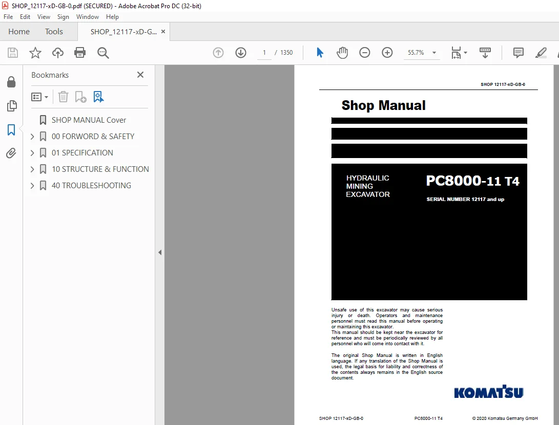
Komatsu Hydraulic Mining Shovel PC8000-11 T4 Shop Manual – PDF DOWNLOAD
$37.95
Komatsu Hydraulic Mining Shovel PC8000-11 T4 Shop Manual – PDF DOWNLOAD
SERIAL NUMBER 12117 and up
Description
Komatsu Hydraulic Mining Shovel PC8000-11 T4 Shop Manual – PDF DOWNLOAD
FILE DETAILS:
Komatsu Hydraulic Mining Shovel PC8000-11 T4 Shop Manual – PDF DOWNLOAD
Language : English
Pages :1350
Downloadable : Yes
File Type : PDF
DESCRIPTION:
Komatsu Hydraulic Mining Shovel PC8000-11 T4 Shop Manual – PDF DOWNLOAD
SERIAL NUMBER 12117 and up
SAFETY INFORMATION
To enable you to use this excavator safely, and to prevent injury to operators, service personnel or bystanders, the
precautions and warnings included in this manual and the safety signs attached to the excavator must always be
followed.
The safety information in this manual does not replace any safety rules or laws in your area.
To identify important safety messages in the manual and on the excavator labels, the following signal words are
used.
The “Safety Alert Symbol” identifies important safety messages on excavators, in manuals, and elsewhere. When
you see this symbol, be alert to the risk of personal injury or death. Follow the instructions in the safety message
TABLE OF CONTENTS:
Komatsu Hydraulic Mining Shovel PC8000-11 T4 Shop Manual – PDF DOWNLOAD
SERIAL NUMBER 12117 and up
SHOP MANUAL Cover 1
00 FORWORD & SAFETY 3
1 Foreword 5
11 BEFORE READING THIS MANUAL 6
111 CSA (Canadian Standards Association) 6
12 CONTENTS OF THIS BINDER 7
121 Contacting the Service 7
122 Guarantee 7
13 DIVISION OF THE BINDER 8
2 SAFETY 9
21 SAFETY INFORMATION 10
22 OVERVIEW 11
221 NORMAL OPERATIONS 11
222 REGULAR MAINTENANCE 11
223 TROUBLESHOOTING, ADJUSTMENTS AND REPAIR 11
224 ADDITIONAL SAFETY PRECAUTIONS 11
23 SOUND PRESSURE AND VIBRATION LEVELS IN THE OPERATOR’S CAB 12
231 SOUND 12
232 VIBRATION 12
24 GENERAL PRECAUTIONS COMMON TO OPERATION ON THE EXCAVATOR 13
241 UNDERSTANDING THE excavator 13
242 PRECAUTIONS BEFORE STARTING OPERATION ON THE EXCAVATOR 13
2421 ENSURING SAFE OPERATION 13
243 PREPARATIONS FOR SAFE OPERATION 13
2431 PRECAUTIONS REGARDING SAFETY RELATED EQUIPMENT 13
2432 INSPECTING THE excavator 13
2433 WEAR WELL FITTING CLOTHES AND PROTECTIVE EQUIPMENT 14
2434 KEEP excavator CLEAN 14
2435 PRECAUTIONS INSIDE OPERATOR’S COMPARTMENT 14
2436 PROVIDE FIRE EXTINGUISHER AND FIRST AID KIT 15
2437 IF A PROBLEM IS FOUND 15
244 FIRE PREVENTION 15
2441 PRECAUTIONS TO PREVENT FIRE 15
2442 ACTION IF FIRE OCCURS ON PC3000 16
2443 ACTION IF FIRE OCCURS ON PC4000, PC5500, PC7000, PC8000 17
2444 EMERGENCY EXIT FROM OPERATOR’S CAB 17
245 PRECAUTIONS WHEN GETTING ON OR OFF THE EXCAVATOR 18
2451 USE HANDRAILS AND STEPS WHEN GETTING ON OR OFF THE excavator 18
2452 NO JUMPING ON OR OFF THE excavator 18
2453 NO PEOPLE ON THE ATTACHMENT 18
2454 WORKING IN HIGH PLACES 18
2455 LEAVING OPERATOR’S SEAT WITH LOCK 19
2456 LEAVING THE excavator 19
246 BURN PREVENTION 19
2461 Hot coolant 19
2462 Hot oil 20
247 PRECAUTIONS WHEN CLEANING CAB GLASS 20
248 PRECAUTIONS RELATED TO PROTECTIVE STRUCTURES 20
249 PRECAUTIONS RELATED TO AIRBOURNE AND EJECTED DEBRIS 21
2491 UNAUTHORIZED MODIFICATION 21
2492 PRECAUTIONS RELATED TO ATTACHMENTS AND OPTIONS 21
2410 ELECTROMAGNETIC COMPATIBILITY (EMC) 21
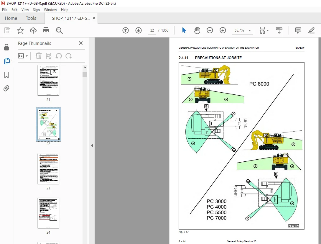
2411 PRECAUTIONS AT JOBSITE 22
24111 VISIBILITY FROM OPERATOR’S SEAT 23
24112 CAMERA SYSTEM WITH MONITORS 23
24113 ENSURE GOOD VISIBILITY 23
24114 CHECKING SIGNS AND SIGNALMAN’S SIGNALS 23
24115 INVESTIGATE AND CONFIRM JOBSITE CONDITIONS 24
24116 DO NOT GO CLOSE TO HIGH VOLTAGE CABLES 24
24117 Lightning Strikes 25
24118 WORKING ON LOOSE GROUND 25
24119 GAS, DUST, STEAM, SMOKE AND EXHAUST FUMES 26
241110 VENTILATION OF ENCLOSED AREAS 27
2412 STARTING motor 28
24121 WARNING TAG 28
24122 CHECKS BEFORE STARTING motor 28
24123 PRECAUTION WHEN STARTING motor 28
24124 PRECAUTION IN COLD AREAS 29
2413 OPERATION 29
24131 CHECKS BEFORE OPERATION 29
24132 PRECAUTIONS WHEN TRAVELING IN FORWARD OR REVERSE 30
24133 PRECAUTIONS WHEN traveling 31
24134 TRAVELING ON SLOPES 32
24135 OPERATIONS ON SLOPES 33
24136 PROHIBITED OPERATIONS 33
24137 TRAVELING ON FROZEN OR SNOW COVERED SURFACES 34
24138 PARKING THE excavator 34
24139 TRANSPORTATION 34
25 PRECAUTION FOR MAINTENANCE 35
251 GENERAL PRECAUTIONS 35
2511 SELECTION AND QUALIFICATION OF PERSONNEL – BASIC RESPONSIBILITIES 36
2512 STOP motor FOR MAINTENANCE 37
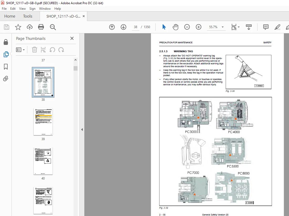
2513 WARNING TAG 38
2514 Maintenance safety Switch 39
2515 KEEP WORKPLACE CLEAN AND TIDY 39
2516 APPOINT LEADER WHEN WORKING WITH OTHERS 39
2517 TWO WORKERS FOR MAINTENANCE WHEN THE excavator IS RUNNING 40
2518 INSTALLING, REMOVING OR STORING ATTACHMENTS 40
2519 PRECAUTIONS WHEN WORKING UNDER THE excavator OR EQUIPMENT 41
25110 NOISE 41
25111 WHEN USING A HAMMER 41
25112 PROPER TOOLS 42
25113 ACCUMULATOR 42
25114 PERSONNEL 42
252 PRECAUTIONS FOR INSPECTION AND MAINTENANCE 43
2521 PRECAUTION WHEN WELDING 43
2522 BATTERY HANDLING 43
253 PRECAUTIONS WITH HIGH PRESSURE FLUID 44
2531 PRECAUTIONS WITH HIGH FUEL PRESSURE 45
2532 HANDLING HIGH PRESSURES HOSES OR PIPES 46
2533 REPLACEMENT OF HOSE LINES 46
2534 INSPECTION OF HOSE LINES 46
2535 PERIODIC REPLACEMENT OF SAFETY CRITICAL PARTS 47
2536 PRECAUTIONS FOR HIGH VOLTAGE 47
2537 AIR CONDITIONING MAINTENANCE 47
2538 COMPRESSED AIR 48
2539 WASTE MATERIALS 48
26 ADDITIONAL SAFETY INFORMATION FOR TROUBLESHOOTING AND ADJUSTMENTS 49
261 INSPECTION OF THE HYDRAULIC SYSTEM 49
262 TWO WORKERS ONLY WHEN THE EXCAVATOR IS RUNNING DURING ADJUSTMENTS 49
263 AREAS OF POTENTIAL DANGER AROUND THE EXCAVATOR 49
27 SPECIAL SAFETY EQUIPMENT 50
271 FRONT GUARD PROTECTIVE STRUCTURe ’FOPS’ FOR OPERATOR’S CAB 51
272 OBJECT HANDLING 51
273 LIGHTING 51
274 WARNING BEACON 51
275 SAFETY HARNESS IN CONFORMITY WITH EN 361 (EUROPEAN STANDARD) 51
2751 SAFETY HARNESS IN CONFORMITY WITH EN 361 (EUROPEAN STANDARD) 51
2752 INSTRUCTIONS FOR USE 53
2753 PRIOR TO USING THE HARNESS (1), THE WEARER SHALL 55
2754 RECOMMENDATIONS FOR USE OF THE HOLDING HOOKS AND HOLD- BACK HOOKS OF THE SAFETY HARNESS 55
2755 INSTRUCTIONS FOR USE 57
01 SPECIFICATION 59
PC8000-11 T4 61
10 STRUCTURE & FUNCTION 71
TOC 73
1 Introduction 85
11 Foreword 86
12 Recommendations for environmentally friendly operation and maintenance of hydraulic mining excavators 87
13 Explanation of abbreviations 88
14 Diagrams and illustrations in this manual 89
2 Specifications 91
21 Lifting Gears 92
22 Safety hints for sling accessory 94
23 Standard Tightening Torque Chart 95
24 Conversion Table 96
25 Blind plugs 102
26 Classification of threads to the nominal width 104
27 Plugs and fittings according to ISO 8434-1 / DIN 2353 105
3 Main assembly groups 107
31 General layout 108
32 Superstructure 110
33 Machinery house 112
34 Hydraulic oil tank 114
35 Hydraulic oil cooler 116
36 Fuel tank 118
37 Cab support 120
38 Operator’s cab 122
39 Control blocks 124
310 Slew machinery 126
3101 Slew machinery (type 2063) 126
3102 Slew machinery (type 632770) 128
311 Undercarriage 130
312 Slew ring 132
313 Attachment 134
3131 Front Shovel Attachment (FSA) 134
3132 Backhoe Attachment (BHA) 135
314 Counterweight 136
315 Safety circuit 138
3151 Wiring Diagram overview → 20S105 / 20S105a 139
3152 Wiring Diagram overview → 70B122a 141
3153 Wiring Diagram overview → 55B023a 142
316 Stabilized voltage circuit – overview 144
317 KomVision camera system 146
4 Drive 147
41 Prime drive assembly 148
42 Engine mounts 150
43 Drive shaft 152
44 Flexible coupling 154
45 Fan drive and radiator assembly 156
451 Radiator fan speed adjustment 160
46 Pump distributor gearbox (PTO) – type 2063 164
461 Pump drive shaft housing / spline lubrication 166
462 PTO lubrication and cooling 168
4621 Checks and adjustments 170
463 Hydraulic pumps – location, drive speed & flow rates 172
47 Air filter 174
48 Exhaust gas aftertreatment (T4 final) 176
481 DEF system layout 178
482 DEF tank – location & overview 180
483 Dosing pumps at DEF tank 182
484 Coolant supply for DEF tank heating circuit 184
485 Information on DEF (Diesel Exhaust Fluid) 186
4851 DEF refilling line 186
4852 DEF Maintenance information 187
4853 Notes on DEF quality and temperature – Important 187
4854 DEF storage 187
4855 Common names used for DEF (Diesel Exhaust Fluid) 187
486 DEF tank level 188
487 SCR catalyst for exhaust gas aftertreatment 190
4871 Dosing valve 193
488 Wiring between engine → DEF tank → SCR catalyst 194
489 Fuel cooling 196
5 Hydraulic oil tank 199
51 General layout 200
52 Location of the electric equipment 202
53 Suction oil tank with strainers 204
54 Return oil collector pipe with strainer 206
55 Back pressure valve 208
56 Transfer pump 210
57 Return and leak oil filter 212
58 Breather filter 214
6 Hydraulic oil cooling 217
61 Overall view of the hydraulic oil cooling 218
62 Function of the hydraulic oil cooling circuit 220
621 Standard hydraulic oil cooling circuit 220
622 Additional oil cooling circuit 222
63 Adjustment of the back pressure valve 224
64 Fan drive – standard oil cooler 226
641 Two stage cooler fan drive RPM control 226
642 Fixed displacement pump with variable setting 228
643 Pressure relief valves 230
644 Solenoid valves 232
65 Adjustment of cooler fan drive speed 234
651 Maximum speed 234
652 Medium speed 238
66 Fan drive – additional oil cooler 240
661 Function of the additional cooler fan RPM control 241
662 Adjustment of the additional cooler fan drive speed 241
7 Controlling 243
71 General layout 244
72 Control and filter panels – location of components 246
721 Main valve cartridge block 246
722 Control and filter panels mounted on the PTOs 252
73 Pilot pressure supply and adjustments 256
731 Pilot pressure control circuit (PPC) 257
732 Checks and adjustments of pilot pressure 260
733 Remote control valves arrangement 262
74 Function of the electro-hydraulic control system 264
741 Control lever signal flow 266
75 Hand lever (joystick) control 268
76 Foot pedal control 270
77 Proportional amplifier & ramp time function 272
771 Used amplifier modules 273
772 Amplifier terminal layout 273
78 Amplifier & ramp time setting via WPC software tool 274
781 Setting preparation 274
782 Basic setting 275
783 Amplifier adjustment 276
79 Troubleshooting 277
791 Error code chart 278
792 LED indication at amplifier modules 279
793 Adjustment values for amplifier & ramp time setting → FSA (example) 280
794 Adjustment values for amplifier & ramp time setting → BHA (example) 282
8 Components 285
81 Main control blocks & high pressure screens (FSA/BHA) 286
811 Control block circuits & valves (FSA) 288
812 Main control blocks – spool & function (FSA) 289
82 Control block circuits & valves (BHA) 290
821 Main control blocks – spool & function (BHA) 291
83 Distributor manifold – location of restrictor blocks & anti-cavitation valves (FSA) 292
84 Distributor manifold – location of restrictor blocks & anti-cavitation valves (BHA) 294
85 Restrictor block with secondary relief valve 296
86 Anti-cavitation valve (ACV) block 298
861 ACV block on control blocks 298
862 ACV block on top of the manifold 300
87 Remote control valves 302
88 4/3 Directional solenoid valves 304
89 Proportional solenoid valves 306
810 High-pressure screen 308
811 Control blocks and valves 310
8111 Spin lock for valve blocks (ND52) 311
8112 Spool types 312
8113 4-spool valve block 314
8114 Control block – spool positions 316
8115 MRV, SRV, and ACV 318
8116 Load holding valve 320
812 Travel brake valve 322
813 Pressure reducing valve 324
814 4/2 Directional valves 326
815 Pressure double stage valve 328
816 Hydraulic cylinder 330
8161 Hydraulic cylinder – Chesterton® 11KE sealing 330
8162 Cylinder data markings 333
9 Main hydraulic pumps and pump regulation 335
91 General layout 336
911 Pump regulation system (“open sensing system”) 338
912 Pump regulation system – valve function 340
92 Main pumps 342
921 Pump bearing flushing / lubrication 344
93 Operating principle of main pumps 346
931 Symbol of main hydraulic pump A4VSO750i 348
932 Sectional drawing of regulating valves 350
933 Main pumps at Qmin (190 l/min, no lever or pedal activated) 352
934 Main pump at Qmax 354
935 Main pump at ½ Qmax 356
936 Main pump destroking 358
937 Main pump – pressure cut-off 360
94 Checks / adjustments – overview 362
941 Checks / adjustments – start of destroking 364
942 Checks / adjustments – Pressure cut-off valve 366
943 Checks / adjustments – Qmin/max stop bolt 368
95 Electronic pump regulation system 370
951 Electronic load limiting control – general 371
952 Microcontroller RC4-4 372
96 Checks and adjustments (RC4-4) 374
961 X1 pressure adjustment – Method A 376
962 X1 pressure adjustment – Method B 378
97 Hydraulic constant regulation system 382
971 General 383
972 Function check of electronic load limit regulation (RC4-4) 384
973 X1 pressure adjustment (constant pressure) 386
98 Power check (engine performance) 388
99 Engine speed sensor (pick-up) 392
991 General 393
992 Engine speed sensor (pick-up) adjustment 393
993 In case of problems – when correct speed sensor adjustment is guaranteed 393
910 Energy efficiency 394
9101 General 395
9102 Checks and adjustments 396
10 Operating hydraulics 399
101 General 400
102 Floating function – boom & stick cylinder (FSA) 402
103 Hydraulics for the attachment cylinders 404
1031 Electric / hydraulic flowchart → Boom UP (FSA) 404
1032 Electric / hydraulic flowchart → Boom UP (BHA) 406
1033 Electric / hydraulic flowchart → Boom down (FSA) Auto-float ON 408
1034 Electric / hydraulic flowchart → Boom down (FSA) Auto-float OFF 410
1035 Electric / hydraulic flowchart → Boom down (BHA) 412
1036 Electric / hydraulic flowchart → Stick out (FSA) 414
1037 Electric / hydraulic flowchart→ Stick out (BHA) 416
1038 Electric / hydraulic flowchart → Stick in (FSA) Auto-float ON 418
1039 Electric / hydraulic flowchart → Stick in (FSA) Auto-float OFF 420
10310 Electric / hydraulic flowchart → Stick in (BHA) 422
10311 Electric / hydraulic flowchart → Bucket fill (FSA) 424
10312 Electric / hydraulic flowchart → Bucket fill (BHA) 426
10313 Electric / hydraulic flowchart → Bucket dump (FSA) 428
10314 Electric / hydraulic flowchart → Bucket dump (BHA) 430
10315 Electric / hydraulic flowchart → Clam open (FSA) 432
10316 Electric / hydraulic flowchart → Clam close (FSA) 434
10317 Checks & adjustments of main relief valves (MRV) 436
10318 Checks & adjustments of secondary relief valves (SRV) 438
103181 SRV boom cylinder, piston side → Boom up (FSA & BHA) 438
103182 SRV boom cylinder, rod side → Boom down (FSA & BHA) 442
103183 SRV Stick cylinder, piston side → Stick out (FSA) 446
103184 SRV Stick cylinder, rod side → Stick out (BHA) 450
103185 SRV stick cylinder, rod side → Stick in (FSA) 454
103186 SRV stick cylinder, piston side → Stick in (BHA) 458
103187 SRV bucket cylinder, piston side → Bucket fill (FSA) 462
103188 SRV bucket cylinder, piston side → Bucket fill (BHA) 466
103189 SRV bucket cylinder, rod side → Bucket dump (FSA) 470
1031810 SRV bucket cylinder, rod side → Bucket dump (BHA) 474
1031811 SRV clam cylinder, rod side → Clam open (FSA) 478
1031812 SRV clam cylinder, piston side → Clam close (FSA) 482
10319 Checks & adjustments of attachment cycle times 486
103191 Check & adjustment → Boom lowering speed (FSA) 486
103192 Check & adjustment → Boom lowering speed (BHA) 490
103193 Check & adjustment → Stick retract speed (FSA) 494
103194 Check & adjustment → Stick retract speed (BHA) 498
103195 Check & adjustment → Bucket dump speed (FSA) 502
103196 Check & adjustment → Bucket dump speed (BHA) 506
103197 Check & adjustment → Clam close speed (FSA) 510
104 Hydraulics for the slew circuit 512
1041 Slew circuit 512
1042 Slew motor 516
1043 Slew gearbox – type 2063 518
1044 Slew gearbox – type 632770 520
1045 Slew parking brake – on slew gear type 2063 522
1046 Slew parking brake – on slew gear type 632770 524
1047 Slew brake valve 526
1048 Electric / hydraulic flowchart → Slew left 530
1049 Electric / hydraulic flowchart → Slew right 532
10410 Checks and adjustments for the slew circuit 534
10411 Function check for hydraulic slew brake 538
10412 Function check for slew parking brake 542
105 Hydraulics for the travel circuit 546
1051 Travel circuit 548
1052 Travel motor 550
1053 Rotary joint 552
1054 Travel gearbox 554
1055 Travel parking brake (on travel gear type 2063) 556
1056 Travel parking brake (on travel gear type 631053) 558
1057 Travel brake valve 560
1058 Electric / hydraulic flowchart → Travel forward 562
1059 Electric / hydraulic flowchart → Travel backward 564
10510 Checks & adjustments for the travel circuit 566
10511 Function check for travel parking brake 568
11 Hydraulic track tensioning system 571
111 General 572
112 Functional description 574
1121 Hydraulic circuit diagram (track tensioning) 576
113 Double-stage valve 578
114 Tensioning cylinder 580
115 Check & adjustment 582
12 Access stairway, hydraulically operated 585
121 Overview 586
122 Function of the hydraulically operated access stairway 590
123 Adjustments / checks 594
13 Central refilling system (service arm) 597
131 General 598
132 Function 600
14 Hints for reading hydraulic diagram 603
141 General 604
142 Hydraulic symbols 606
1421 Lines, unions 607
1422 Components, valves 609
1423 Sensors 609
1424 Valves, valve components 610
1425 Pump, motor, cylinder 614
15 Hints for reading electric wiring diagram 619
151 General 620
152 Reference designation of the electrical components 621
1521 Area code 621
1522 Component identifying letter 623
153 Graphical symbols 624
154 Drawing concept 628
155 Cable & connector marking 638
16 KOMTRAX Plus & MTC control system 641
161 General 642
1611 Control desk overview 644
1612 SCR & DEF monitoring device for T4 engines 645
162 Specifications for Operators 646
1621 Start screen 647
1622 Opening Screen 647
1623 Main Gauge Screens 14 648
1624 Fuel Consumption Screen 652
1625 Failure message History for Operator 654
1626 Main Gauge Screens – Changing of Time / SMR / Date 656
1627 Maintenance Monitor 658
1628 Settings for Operator 660
1629 Automatic Messages 668
163 Tables of all Provided Messages 670
1631 Table of Error Codes & Messages 671
1632 Table of available Instruction Messages 677
164 Table of C-Codes – Diesel engines QSK60 T4 680
165 Flow Charts (14) of KOMTRAX Plus main screens 708
166 KOMTRAX Plus service level 712
1661 General 713
1662 Explanation of the Button Symbols (Service Level) 714
1663 Service Menu Select Screen 715
1664 Real Time Menu Select Screen 716
16641 Real Time Menu, option: 01 Engine 1 717
16642 Real Time Menu, option: 02 Engine 2 718
16643 Real Time Menu, option: 03 PTO 1 718
16644 Real Time Menu, option: 04 PTO 2 718
16645 Real Time Menu, option: 05 Hydraulic 719
16646 Real Time Menu, option: 06 Slew 720
16647 Real Time Menu, option: 07 Electrical Equipment 721
16648 Real Time Menu, option: 08 Emergency Stop 722
16649 Real Time Menu, option: 09 Manual Switch 723
166410 Real Time Menu, option: 10 Central Lube System 1 724
166411 Real Time Menu, option: 11 Slew Ring Gear Lube System 725
166412 Real Time Menu, option: 12 Central Lube System 2 726
166413 Real Time Menu, option: 13 Windscreen Wiper 727
166414 Real Time Menu, option: 14 Ladder 728
166415 Real Time Menu, option: 15 Service Arm 729
166416 Real Time Menu, option: 16 Pilot Control 730
166417 Real Time Menu, option: 17 Other Items 731
166418 Real Time Menu, option: 18 Output Signals 732
166419 Output Signals with deactivated MTC-Evaluation 735
1665 PM Clinic 736
16651 General 736
16652 Power Check 737
1666 Serial/GCC No Setting 738
1667 Memory Clear 739
16671 Input Memory Clear ID 739
16672 Memory Clear Screen 740
1668 Failure History 741
1669 Maintenance Monitor 742
16610 Snapshot 743
16611 Settings 744
166111 Central Lubrication System (CLS 1), screen 1/10 744
166112 Slew Ring Gear Lubrication System (SLS), screen 2/10 745
166113 Central Lubrication System (CLS 2), screen 3/10 746
166114 Qmin – Qmax – Setting, screen 4/10 747
166115 Other Settings 1/2, screen 5/10 747
166116 Hydraulic Oil & PTO Gear Oil Definition Tables 748
166117 Hydraulic oil temperature charts 748
166118 PTO gear oil temperature charts 748
166119 Other Settings 2/2, screen 6/10 749
1661110 Messages ON/OFF 750
1661111 PLC-evaluation ON/OFF 751
1661112 Shutdown Bypass ON/OFF 752
167 Interface Connection KOMTRAX Plus Controller & MTC 756
168 KOMTRAX Plus controller 757
1681 7-segment error code indication 758
169 Wiring of KOMTRAX Plus Controller 760
1610 MTC control system – global layout 764
16101 MTC (Master Turbo Controller) 766
161011 MTC-Flowchart 766
161012 MTC Features 766
161013 MTC Firmware and Software 767
161014 Connector and component location in the control system 767
161015 View onto the MTC unit and its connectors 768
161016 LED indications at the MTC 769
1611 Global Layout of the Internal CAN BUS 770
16111 General Information on a CAN BUS System 770
161111 General CAN BUS description 771
161112 CAN BUS troubleshooting 771
161113 CAN BUS wiring 772
161114 CAN BUS end resistor 774
1612 The Nodes in the CAN BUS System 776
16121 Global Layout 776
16122 Introduction 778
161221 ICN-V Node Features 778
161222 View onto an open ICN-V node with DIP switches & status LED 780
161223 General information on the LED control 781
161224 ICN-D Features 782
161225 View onto an ICN-D node without wiring 783
161226 View onto the Status LEDs at the ICN-D node 784
161227 General information on the LED control 784
16123 Node DIP-Switches 786
161231 Detailed view onto the DIP switches 787
16124 Node box 788
16125 Node Locations on the Excavator 790
161251 Node & Location Chart 791
16126 View onto Location 11 (Cab base) 792
17 Lubrication system 793
171 General overview SLS & CLS1 / 2 794
1711 General description 795
172 Basic function of lubrication systems 796
173 Lubrication systems (SLS & CLS1/2) 798
1731 Lubrication pump station 800
1732 General Information on CLS1/2 802
1733 General information on SLS 802
1734 Manual lube activation 802
174 Lubrication cycle 803
1741 Operation and control 803
1742 Lubrication cycle – processing 804
1743 Time segments & switch points of a lubrication cycle 805
1744 Lubrication modes 806
17441 Automatic lubrication mode 806
17442 Manual lubrication mode 806
17443 Reduced pause time for service 806
175 Hydraulically driven lube pump 808
1751 Adjustment of lube pump speed 810
17511 Stroke speed adjustment 811
17512 Working pressure 811
176 Lubricant injectors 812
1761 Tightening torques for fittings at grease injectors 813
1762 Description 813
1763 Adjustment of lubricant output 814
1764 Operation principle of lubricant injectors 816
17641 Function description 817
1765 Connection of two or more injectors 818
177 Vent valve & grease outlet filter 820
1771 Vent valve description 821
178 End-line switch 822
1781 Description 823
1782 CLS1/2 end-line switch adjustment 824
1783 SLS end-line switch adjustment 826
179 Lubricant level sensors 828
1791 Description 829
1792 Checks 829
1710 Commissioning 830
17101 Commissioning of CLS 1/2 lubrication system 830
17102 Fine adjustment 831
17103 Commissioning of SLS lubrication system 832
18 Deep temperature equipment (option) 835
181 General information 836
1811 Introduction 836
1812 Deep temperature components overview 836
1813 Power supply preconditions for preheating 837
1814 Power requirements for preheating systems 838
182 Preheating procedure 839
1821 Global flow chart of the preheating procedure 839
1822 Starting the preheating procedure 840
1823 Preheating of operator’s cab and Diesel engine [coolant system] 841
1824 Preheating of lubricants and superstructure (Diesel) [electric system] 842
183 Constant heating of travel motors (TTT equipment below-40°C only) 843
184 Component location 844
1841 Electric heating elements for hydraulic & batteries [electric excavator] 844
1842 Electric heating elements for hydraulics [Diesel excavator] 846
1843 Electric heating elements for engines & batteries [Diesel excavator] 848
185 Components of TT equipment 850
1851 Preheating components on a Diesel excavator 850
1852 Preheating components on an electric excavator 851
1853 Wiring Diagrams for preheating systems 852
18531 Wiring diagram “Hydraulic Oil Tank Preheating” part 1 of 3 852
18532 Wiring diagram “Hydraulic Oil Tank Preheating” part 2 of 3 853
18533 Wiring diagram “Hydraulic Oil Tank Preheating” part 3 of 3 854
18534 Wiring diagram “Suction Oil Manifold Preheating” 855
18535 Wiring diagram “PTO Preheating” 856
18536 Wiring diagram “Battery heater pads” 857
40 TROUBLESHOOTING 859
TOC 861
1 Introduction 875
11 Overview 876
111 General advice when using troubleshooting charts 876
12 General precautions 877
2 General Information for Troubleshooting 879
21 Preparations for work 880
22 Precautions during work 880
23 Precautions when carrying out any operation 881
231 Precautions when carrying out removal work 881
232 Precautions when carrying out installation work 881
233 Precautions when completing the operation 882
24 Fundamental requirements for troubleshooting 883
241 Technical documentation 883
242 Tools 883
2421 Reference guide for Deutsch removal tools 886
243 Personnel 887
25 Points to remember when troubleshooting 887
26 Sequence of events in troubleshooting 889
27 Checks before troubleshooting 890
28 Handling of electric equipment and hydraulic components 891
281 Points to remember when handling electric equipment 891
282 Points to remember when handling hydraulic equipment 893
29 General working procedures 896
291 Air bleeding of various hydraulic parts 896
292 Air bleeding from the hydraulic pumps 896
293 Air bleeding from hydraulic cylinders 896
210 Cylinder bypass test 897
211 Basics about “How to crimp” (with strain relief) 898
2111 Crimp tool & repair kit 898
2112 General 899
2113 Select the required connector components 899
2114 Stripping a wire 900
2115 Crimping 901
2116 Connector assembly after crimping 902
212 Cable shielding 903
3 Mounting Locations and Connector Types 905
31 Superstructure 906
32 Location of electrical parts engine-1 908
321 Location of electrical parts engine-2 910
33 Location of engine remote oil tank sensors 912
34 Location of hydraulic components 914
341 Main valve cartridge block 914
342 Main valve cartridge block – Pressure test ports 916
343 Suction oil tank with strainers 918
344 Control and filter panels mounted on the PTOs 920
345 Remote control valves arrangement 924
35 Hydraulic oil tank – electr components 926
36 View onto CLS1/2 & SLS lubrication station & lubrication cycle components 928
37 Cab base 930
371 View onto location 11 (cab base) 932
38 Batteries, battery main switches & safety switch for maintenance 934
39 Access stairway, hydraulically operated 936
310 Central refilling system (service arm) 938
311 Connector types overview 940
4 Standard Value Table for Electrical Components 947
5 References for troubleshooting (CAN BUS & node outputs) 959
51 CAN-BUS trouble or node output trouble 960
511 Trouble CAN-BUS or CAN-hardware (G00308) 961
512 Trouble Output Short-Circuit (G00043) 962
52 Sequence of CAN nodes in the CAN BUS 964
53 Troubleshooting for relay monitored node outputs 965
531 Relay check 965
G00107 – Trouble slew parking brake control 56K250a 966
G00109 – Trouble slew parking brake control 56K250b 966
View onto CoDeSys visualization screen for trouble code G00107 968
Wiring Diagram (56K250a & 56K250b) for trouble code G00107 969
532 Output check 970
G00108 – Trouble slew parking brake control Output to 56K250a 971
G00110 – Trouble slew parking brake control Output to 56K250b 971
View onto CoDeSys visualization screen for trouble code G00108 973
Wiring Diagram (56K250a & 56K250b) for trouble code G00108 974
6 Tables for Testing and Troubleshooting 975
61 Test value table for temperature sensors (PT100) g Centigrade – Volt 976
62 Test value table for temperature sensors (PT100) g Centigrade – Ohm 977
63 Test value tables for transducers 978
631 Pump press transducers 978
632 Hydraulic oil pressure transducers 979
633 Miscellaneous pressure transducers 980
634 Temperature transducers 981
64 Hydraulic oil temperature charts 982
65 PTO gear oil temperature charts 982
66 Table of trouble codes (G-codes) 983
67 Table of C-Codes – Diesel engines QSK60 T4 989
68 Table of available Instruction Messages 990
69 Table of binary codes 993
691 Table of add-on binary codes for G00308 998
610 Tables of symptom codes 999
6101 Symptoms of engines and related electrical systems 999
6102 Symptoms of hydraulic system 999
6103 Symptoms of mechanical system1000
6104 Symptoms of additional systems1000
611 Power supply1001
612 Cable colour identification1001
7 Troubleshooting by trouble code1003
G00001 – Trouble Shut-Off (gate) valve1004
View onto the gap of proximity switch 40B0311006
Input signal (analog) of proximity switch 40B031 on the REAL TIME MONITOR1007
View onto the setting for SHUTDOWN BYPASS on K+ monitor1007
Wiring Diagram (40B031) for message G00001 (Trouble Shut-Off (gate) valve)1008
G00003 – Trouble pump controller1009
G00005 – Low hydraulic oil level1015
Wiring Diagram, oil level label, and defined attachment position (G00005)1017
G00007 – Trouble hydraulic oil level1018
Wiring Diagram (40B004) and defined attachment position (G00007)1019
G00012 – Central lubrication system grease level too low1020
G00013 – Slew ring gear lubr system grease level too low1020
Wiring Diagram (62B108b & 62B109b) for trouble codes G00012 & G000131023
Wiring Diagram (junction box) for trouble codes G00012 & G000131024
G00020 – Trouble Shut-Off (gate) valve (Start blocked)1025
View onto the gap of proximity switch 40B031 (G00020)1027
Wiring Diagram (40B031) for trouble code G00020 (Main gate valve closed)1028
Input signal (analog) of proximity switch 40B031 on the REAL TIME MONITOR1029
View onto the setting for SHUTDOWN BYPASS on the KOMTRAX Plus monitor1029
G00031 – Set engine to low idle1030
Input signal of engine speed switch 20S030 on the REAL TIME MONITOR1030
Wiring Diagram (20S030) for trouble code G000311031
G00032 – Trouble starter1032
Wiring Diagram (Cold Start Signal Engine 1 & 2) for trouble code G000321033
Wiring Diagram – Engine running signals – for trouble code G000321034
G00033 – Trouble KOMTRAX Plus controller1035
G00034 – Trouble KOMTRAX Plus display1036
G00035 – Trouble totally loss gear oil (PTO 1)1037
G00036 – Trouble totally loss gear oil (PTO 2)1037
View onto the location of sensor 57B175-1 at PTO 1 (G00035)1039
Input signal (analog) of gear oil sensors 57B175-1/-2 on the REAL TIME MONITOR1040
View onto the setting for SHUTDOWN BYPASS on K+ monitor1040
Wiring Diagram (57B175-1/-2) for trouble codes G00035 & G000361041
G00037 – Trouble monitoring, engine 2 speed too low1042
G00038 – Trouble monitoring, engine 2 speed too high1042
G00039 – Actuate engine speed selector switch1042
G00040 – Emergency shut-down pump compartment1043
Wiring Diagram (emergency circuit) for G00040, G00092, G00093, G00095, G000971044
Wiring Diagram (emergency switches) for G00040, G00092, G00093, G00095, G000971045
G00041 – Emergency shut-down pump compartment1046
Wiring Diagram (emergency circuit) for G00041, G00252, G00253, G00255, G002581047
Wiring Diagram (emergency switches) for G00041, G00252, G00253, G00255, G002581048
G00043 – Trouble output short-circuit1049
G00048 – Trouble emergency safety circuit1050
Wiring Diagram (emergency safety circuit) for trouble code G000481051
G00053 – Reset emergency safety circuit1052
G00054 – Monitoring idle position cut off1053
Wiring Diagram (11K032) for trouble code G000541054
Input signal (analog) of relay 11K032 on REAL TIME MONITOR (G00054)1055
Example view onto K+ Failure History (G00054)1055
G00060 – Fire in the power house1056
Wiring Diagram (fire suppression) for trouble code G000601057
G00061 – Trouble monitoring, engine 1 speed too low1058
Input signal of 51K003b-1 & 51K003b-2 on REAL TIME MONITOR1060
Wrong signal of engine 2 speed converter on REAL TIME MONITOR1060
Wiring Diagram (51T018-1/-2) for trouble codes G00061 & G000371061
G00062 – Trouble monitoring, engine 1 speed too high1062
Wiring Diagram (51T018-1/-2) for trouble codes G00062 & G000381063
G00063 – Trouble monitoring hydraulic oil temp1064
Real Time Monitor and Wiring Diagram (59B015) for trouble code G000631065
G00064 – Trouble monitoring hydraulic oil level1066
Real Time Monitor and Wiring Diagram (40B004) for trouble code G000641068
G00065 – Very low hydraulic oil level1069
View onto the hydraulic oil level label1069
G00066 – Trouble hydraulic oil temperature1070
Wiring Diagram (57K506a-1/57K506b-1 & 57K506a-2/57K506b-2) & location for G000661072
G00067 – Trouble battery voltage too high1074
Wiring Diagram (11T080), component location & Real Time Monitor for G000671075
G00068 – Trouble gear lubrication (PTO 2)1075
G00069 – Trouble monitoring oil temperature gear (PTO 1)1076
Input of 57B049-1 on the REAL TIME MONITOR (G00069)1077
Gear oil temperature (PTO 1 & PTO 2) on Main Gauge Screen1077
Wiring Diagram (57B049-1 & 57B049-2) & component location (G00069 & G00083)1078
G00070 – Trouble oil temperature gear (PTO 1)1079
Location of PTO gear oil level dipstick & temp sensors 57B049-1/57B049-21081
G00071 – Trouble gear lubrication (PTO 1)1082
Wiring Diagram (57B017-1 & 57B017-2) for trouble codes G00071 & G000681083
G00072 – Trouble monitoring hydraulic oil level1084
Wiring Diagram (40B105) and REAL TIME MONITOR for G000721085
G00073 – Trouble monitoring remote engine oil level 11086
Wiring Diagram (63B106-1/-2) and REAL TIME MONITOR for G00073 & G000821087
G00076 – Trouble monitoring pressure suction tank1088
Wiring Diagram (59B162) and REAL TIME MONITOR for G000761089
G00079 – Trouble monitoring pressure oil cooler 11090
Wiring Diagram (40B165) and REAL TIME MONITOR for G000791091
G00080 – Trouble monitoring pressure pre-load valve1092
Wiring Diagram (40B166) and REAL TIME MONITOR for G000801093
G00081 – Trouble lubrication system1094
Operation cycles of the lubrication systems1096
Wiring Diagram (11K050) for trouble code G000811097
G00082 – Trouble monitoring remote engine oil level 21097
G00083 – Trouble monitoring oil temperature gear (PTO 2)1097
G00084 – Trouble oil temperature gear (PTO 2)1097
G00086 – SHUTDOWN1098
G00087 – Stop all movements for low idle1099
G00090 – Trouble power supply1100
Wiring Diagram (11F013 & 11F013a) for G00090 & G000991101
G00091 – Pilot control cut out1102
G00092 – Emergency shut-down at access ladder1103
G00093 – Emergency shut-down at valve block1103
G00095 – Emergency shut-down in cabin1103
G00096 – Pilot control cut out1104
Wiring Diagram (20S094) & REAL TIME MONITOR for trouble code G000961105
G00097 – Emergency shut-down at counterweight1105
G00099 – Trouble power supply1105
G00100 – Maintenance Safety Switch1106
Wiring Diagram (50S058) for trouble code G001001107
G00103 – Faulty switch 20M0041108
REAL TIME MONITOR for windscreen wiper1109
Wiring Diagram (windscreen wiper) for trouble code G001031110
G00104 – Trouble battery current1111
Wiring Diagram (battery current) for trouble code G001041113
G00105 – Trouble battery charging current too low1114
Wiring Diagram (11T080) & REAL TIME MONITOR for trouble code G001051115
G00107 – Trouble slew parking brake control 56K250a1116
View onto CoDeSys visualization screen for trouble code G001071118
Wiring Diagram (56K250a & 56K250b) for trouble code G001071119
G00108 – Trouble slew parking brake control Output to 56K250a1120
View onto CoDeSys visualization screen for trouble code G001081122
Wiring Diagram (56K250a & 56K250b) for trouble code G001081123
G00109 – Trouble slew parking brake control 56K250b1124
G00110 – Trouble slew parking brake control Output to 56K250b1124
G00111 – Trouble travel parking brake control 56K251a1124
56K251a & 56K251b (relay check) on REAL TIME MONITOR (G00111 & G00113)1124
G00112 – Trouble travel parking brake control Output to 56K251a1125
56K251a & 56K251b (output check) on REAL TIME MONITOR (G00112 & G00114)1125
G00113 – Trouble travel parking brake control 56K251b1126
G00114 – Trouble travel parking brake control Output to 56K251b1126
G00115 – Trouble slew hydraulic brake control 56K252a1126
56K252a & 56K252b (relay check) on REAL TIME MONITOR (G00115 & G00117)1126
G00116 – Trouble slew hydraulic brake control Output to 56K252a1127
56K252a & 56K252b (output check) on REAL TIME MONITOR (G00116 & G00118)1127
G00117 – Trouble slew hydraulic brake control 56K252b1127
G00118 – Trouble slew hydraulic brake control Output to 56K252b1127
G00139 – Trouble monitoring X1-2 pressure1128
G00140 – Trouble monitoring X1-1 pressure1128
57B085-1 & 57B085-2 on REAL TIME MONITOR (G00139 & G00140)1129
Wiring Diagram of 57B085-1 & 57B085-2 for trouble codes G00139 & G001401130
G00141 – Trouble monitoring X2 pressure1131
57B086 on REAL TIME MONITOR (G00141)1132
Wiring Diagram (57B086) for trouble code G001411133
G00143 – Trouble monitoring 61B087a1134
G00144 – Trouble monitoring 61B087b1134
G00145 – Trouble monitoring 61B087c1134
G00146 – Trouble monitoring 61B087d1134
Wiring Diagram (61B087ad) for message G001431461136
G00147 – Trouble monitoring gear lubrication (PTO 1)1137
Wiring Diagram (57B017-1 & 57B017-2) for trouble codes G00147 & G001501140
G00148 – Trouble monitoring fuel level1141
REAL TIME MONITOR, Wiring Diagram & component location (31B063) for G001481143
G00149 – Trouble monitoring ambient temperature1144
REAL TIME MONITOR and Wiring Diagram (13B090) for G001491145
G00150 – Trouble monitoring gear lubrication (PTO 2)1145
G00151 – Trouble monitoring gear (PTO) oil filter 11146
Wiring Diagram (57B027-1/-2) and location for trouble codes G00151 & G001931149
G00154 – Trouble monitoring return oil filter1150
REAL TIME MONITOR and Wiring Diagram (40B163) for trouble code G001541152
G00155 – Trouble monitoring leak oil filter1153
Wiring Diagram (40B164) for trouble code G001551155
G00159 – Trouble monitoring breather filter1156
Wiring Diagram (40B024) for trouble code G001591158
G00160 – Trouble monitoring engine air cleaner 11159
Wiring Diagram (52B018-1/-2 & 52B019-1/-2) for trouble codes G00160 & G001971162
G00161 – Trouble monitoring battery voltage1163
Wiring Diagram & component location (11T080) for trouble code G001611165
G00162 – Trouble monitoring charging-/discharging current1166
Wiring Diagram (battery charging current) for trouble code G001621168
G00164 – Trouble air cleaner 11170
View onto an engine air cleaner (G00164 & G00198)1171
G00165 – Trouble breather filter hydraulic oil tank1172
Location of 40B024 & sight glass with hydraulic oil temp label (G00165)1173
G00166 – Trouble oil filter gear (PTO 1)1174
View onto PTO 1/2 gear oil filter with pressure sensor 57B027-1/-2 (G00166/G00191)1175
G00169 – Trouble return oil filter hydraulic oil tank1176
G00170 – Trouble leak oil filter hydraulic oil tank1177
G00176 – Trouble battery voltage too low1178
Wiring Diagram (batteries) for trouble code G001761180
G00177 – Trouble battery charging circuit1182
Wiring Diagram (measuring points 13) for trouble code G001771183
G00178 – Trouble battery charging current too high1184
Wiring Diagram & REAL TIME MONITOR (51T017) for trouble code G001781185
G00179 – Trouble control pressure X1-11186
57B085-1/-2 at valve cartridge block (G00179 & G00182)1187
G00180 – Trouble pilot pressure X2 too low1188
Valve cartridge block with X2 pressure transducer 57B086 & M121189
G00181 – Trouble pilot pressure X2 too high1190
Valve cartridge block with X2 pressure transducer 57B086 & M121191
G00182 – Trouble control pressure X1-21191
G00184 – Central lubrication system empty1192
G00185 – Trouble central lubrication system1194
Allocation of vent valves and end-of-line switches1195
Action chart for lube cycles1196
View onto vent valve (62Q507a – 62Q509a – 62Q642a)1197
Wiring Diagram (60B043/62B046/80B043) for trouble codes G00185/G00188/G002031198
G00186 – Trouble central lubrication system1199
Allocation of vent valves1199
Action chart for lube cycles1200
View onto the vent valve (62Q507a – 62Q509a – 62Q642a)1201
G00187 – Slew ring gear lubrication system empty1202
G00188 – Trouble slew ring gear lubrication system1202
G00189 – Trouble slew ring gear lubrication system1202
G00191 – Trouble oil filter gear (PTO 2)1202
G00193 – Trouble monitoring gear (PTO) oil filter 21202
G00197 – Trouble monitoring engine air cleaner 21202
G00198 – Trouble air cleaner 21202
G00203 – Trouble attachment lubrication system1202
G00204 – Trouble attachment lubrication system1202
G00207 – Engine remote oil tank 1 empty1203
G00208 – Engine remote oil tank 2 empty1203
G00216 – Trouble software not compatible1204
G00218 – Switch off all motors for running transfer pump1206
G00219 – Return oil tank empty1207
Sensor 40B068 (return oil level) on REAL TIME MONITOR1207
G00220 – Trouble transfer pump motor overheated1208
Wiring Diagram (transfer pump) for trouble code G002201209
G00223 – Trouble starter control 51K001a-11210
51K001a-1/-2 & 51K001b-1/-2 (relay check) on REAL TIME MONITOR1210
G00224 – Trouble starter control Output to 51K001a-11211
51K001a-1/-2 & 51K001b-1/-2 (output check) on REAL TIME MONITOR1211
G00225 – Trouble starter control 51K001b-11212
G00226 – Trouble starter control Output to 51K001b-11212
G00227 – Trouble starter control 51K001a-21212
G00228 – Trouble starter control Output to 51K001a-21212
G00229 – Trouble starter control 51K001b-21212
G00230 – Trouble starter control Output to 51K001b-21212
G00231 – Trouble pilot control lever 20S0191213
G00232 – Trouble pilot control lever 20S0201213
Wiring Diagram (20S019) for trouble code G002311214
Wiring Diagram (20S020) for trouble code G002321215
G00233 – Trouble pilot control 11Q0451216
Electronic power relay 11Q045 on REAL TIME MONITOR1216
Wiring Diagram (11Q045) for trouble code G002331217
G00234 – Trouble pilot control 11K111a1218
11K111a & 11K111b (relay check) on REAL TIME MONITOR (G00234 & G00236)1218
G00235 – Trouble pilot control Output to 11K111a1219
11K111a & 11K111b (output check) on REAL TIME MONITOR (G00235 & G00237)1219
G00236 – Trouble pilot control 11K111b1219
G00237 – Trouble pilot control Output to 11K111b1219
G00238 – Trouble supply by key switch 11Q0441220
Input signal of 11Q044 on REAL TIME MONITOR (G00238)1220
G00239 – Trouble electrical matter1222
Wiring Diagram – signal line 10K3511223
G00240 – Trouble hydraulic oil temperature1224
Hydraulic oil temperature charts1225
G00242 – Engine 1 already running1226
G00243 – Fill up fuel tank1226
G00245 – Engine shutdown from ground1227
Wiring Diagram – 54S051 & 54S0521228
G00246 – Hydraulic oil temperature1229
G00248 – Engine 2 already running1230
G00252 – Emergency shut-down at access ladder1230
G00253 – Emergency shut-down at valve block1230
G00255 – Emergency shut-down in cabin1230
G00257 – Hydraulic oil temperature1231
G00258 – Emergency shut-down at counterweight1231
G00261 – Maintenance Safety Switch1232
G00262 – Trouble screen at hydr cooler entry clogged1233
40B166 and 40B165 on REAL TIME MONITOR (05 Hydraulic)1233
Location of 40B166 and 40B165 at collector pipe (G00262)1234
G00308 – Trouble CAN-BUS or CAN-Hardware1235
G00309 – Trouble ladder up 56K253a1238
56K253a & 56K253b (relay check) on REAL TIME MONITOR (G00309 & G00311)1238
G00310 – Trouble ladder up Output to 56K253a1239
56K253a & 56K253b (output check) on REAL TIME MONITOR (G00310 & G00312)1239
G00311 – Trouble ladder up redundant Output to 56K253b1239
G00312 – Trouble ladder up redundant 56K253b1240
G00313 – Trouble ladder down 56K254a1240
56K254a & 56K254b (relay check) on REAL TIME MONITOR (G00313 & G00315)1240
G00314 – Trouble ladder down Output to 56K254a1241
56K254a & 56K254b (output check) on REAL TIME MONITOR (G00314 & G00316)1241
G00315 – Trouble ladder down redundant 56K254b1241
G00316 – Trouble ladder down redundant Output to 56K254b1242
G00317 – Trouble service arm up 56K255a1242
56K255a & 56K255b (relay check) on REAL TIME MONITOR (G00317 & G00319)1242
G00318 – Trouble service arm up Output to 56K255a1243
56K255a & 56K255b (output check) on REAL TIME MONITOR (G00318 & G00320)1243
G00319 – Trouble service arm up redundant 56K255b1243
G00320 – Trouble service arm up redundant Output to 56K255b1244
G00321 – Trouble service arm down 56K256a1244
56K256a & 56K256b (relay check) on REAL TIME MONITOR (G00321 & G00323)1244
G00322 – Trouble service arm down Output to 56K256a1245
56K256a & 56K256b (output check) on REAL TIME MONITOR (G00322 & G00324)1245
G00323 – Trouble service arm down redundant 56K256b1245
G00324 – Trouble service arm down redundant Output to 56K256b1245
G00325 – Trouble service arm Input1246
G00326 – Trouble ladder Input1246
G00327 – Trouble parking brake Input1246
G00328 – Trouble start Input1246
G00331 – Automatic after_running engine 11249
G00332 – Automatic after_running engine 21249
G00349 – Engine 2 running1249
G00351 – Engine 1 running1249
G00350 – Engine 2 standstill1249
G00352 – Engine 1 standstill1249
G00417 – Communication failure PLC <=> KOMTRAX Plus controller1250
G00420 – Connector sel error1251
G00421 – Farm sys error1252
G00422 – Can-net sys (J1939)1254
Wiring Diagram (CAN BUS Quantum ↔ K+ controller) for message G004221255
G00425 – Settings impossible to take over into the PLC1256
Wiring Diagram overview for G00425: K+ monitor → K+ controller → MTC1257
G00491 – Communication failure MH800 <=> KOMTRAX Plus controller1258
Wiring Diagram overview for G00491: MH801 ↔ K+ controller1259
8 Troubleshooting by Symptoms1261
81 Symptoms of Engines and Related Electrical Systems1262
SEL001 – Engine does not start (engine does not rotate)1262
Wiring Diagram 1 (batteries) for trouble code SEL0011264
Wiring Diagram 2 (20S030 & 20S105) for trouble code SEL0011265
Wiring Diagram 3 (engine 1 start) for trouble code SEL0011266
Wiring Diagram 4 (11G044) for trouble code SEL0011267
SEL002 – Engine stops while in operation1268
View onto fuel system water separator (SEL002)1269
SEL003 – Engine speed is hunting during boom-up movement1270
SEL004 – Engine does not stop1271
SEL005 – Engine lacks output (no power)1272
Judgment Table for SEL0051273
SEL006 – Engine does not start (Pre-lube does not stop)1274
SEL007 – Oil consumption is excessive1276
Judgment Table for SEL0071277
SEL008 – Oil becomes contaminated quickly1278
Judgment Table for SEL0081279
SEL009 – Fuel consumption is excessive1280
Judgment Table for SEL0091281
SEL010 – Oil is in engine coolant1282
Judgment Table for SEL0101283
SEL011 – Oil level rises1284
Judgment Table for SEL0111285
SEL012 – Coolant temperature becomes too high (overheating)1286
Judgment Table for SEL0121287
82 Symptoms of Hydraulic System1288
SHY001 – All work equipment shows lack of power or slow movement (especially the “boom up” function)1288
SHY002 – Engine speed sharply drops or engine stalls too much1290
SHY003 – No work equipment, travel or slew movement1292
SHY004 – Work equipment has too much hydraulic drift1293
SHY005 – Work equipment has big time lag1294
SHY006 – Excavator deviates during travel movement1295
SHY007 – Hydraulic system has lack of power (Energy Efficiency)1296
SHY008 – Excavator does not slew1298
Slew brake block (SHY008)1299
SHY009 – Slew acceleration is poor1300
SHY010 – Excessive overrun when stopping slew movement1302
SHY011 – Floating system without function (FSA only)1304
SHY012 – Abnormal noise coming from SRV or MRV1305
SHY013 – Track tensioning system without function1306
View onto the elements of the hydraulic track tensioning system (SHY013)1307
SHY014 – Stairway does not move, or slow movement1308
SHY015 – Refilling arm does not move, or slow movement1310
SHY016 – Hydraulic driven grease pump does not move1312
SHY017 – Trouble pump bearing lubrication1314
SHY018 – Abnormal track chain movement during digging1315
SHY019 – Slew parking brake without function1316
SHY020 – Travel parking brake without function1317
83 Symptoms of Mechanical System1318
SME001 – Abnormal noise is made1318
Judgment Table for SME0011319
SME002 – Abnormal noise around PTOs / hydraulic pumps1320
SME003 – Vibration is excessive (engine mountings)1322
Judgment Table for SME0031323
SME004 – Vibration is excessive (engine torsion)1324
SME005 – There is a big shock when stopping slew movement1325
SME006 – There is a big abnormal noise when moving/stopping slew movement1326
SME007 – Fan blades make abnormal noise1328
SME008 – Abnormal noise coming from a travel gearbox1330
SME009 – Abnormal noise coming from work equipment (lack of grease)1332
SME010 – Abnormal idler movement1334
SME011 – Leak at PTO shaft seal1336
84 Symptoms of Additional Systems1338
SAD001 – Air conditioner for the cabin does not work1338
View onto the A/C unit (SAD001)1339
SAD002 – Air conditioner compressor clutch is burnt1340
View onto A/C compressor and its mounting (SAD002)1341
SAD003 – Air conditioning system defective (pipes and hoses full of moisture)1342
View onto an A/C filling and service station1343
SAD004 – CAN BUS failure (message G00308 displayed)1344
IMAGES PREVIEW OF THE MANUAL:
S.M 25/12/24



