
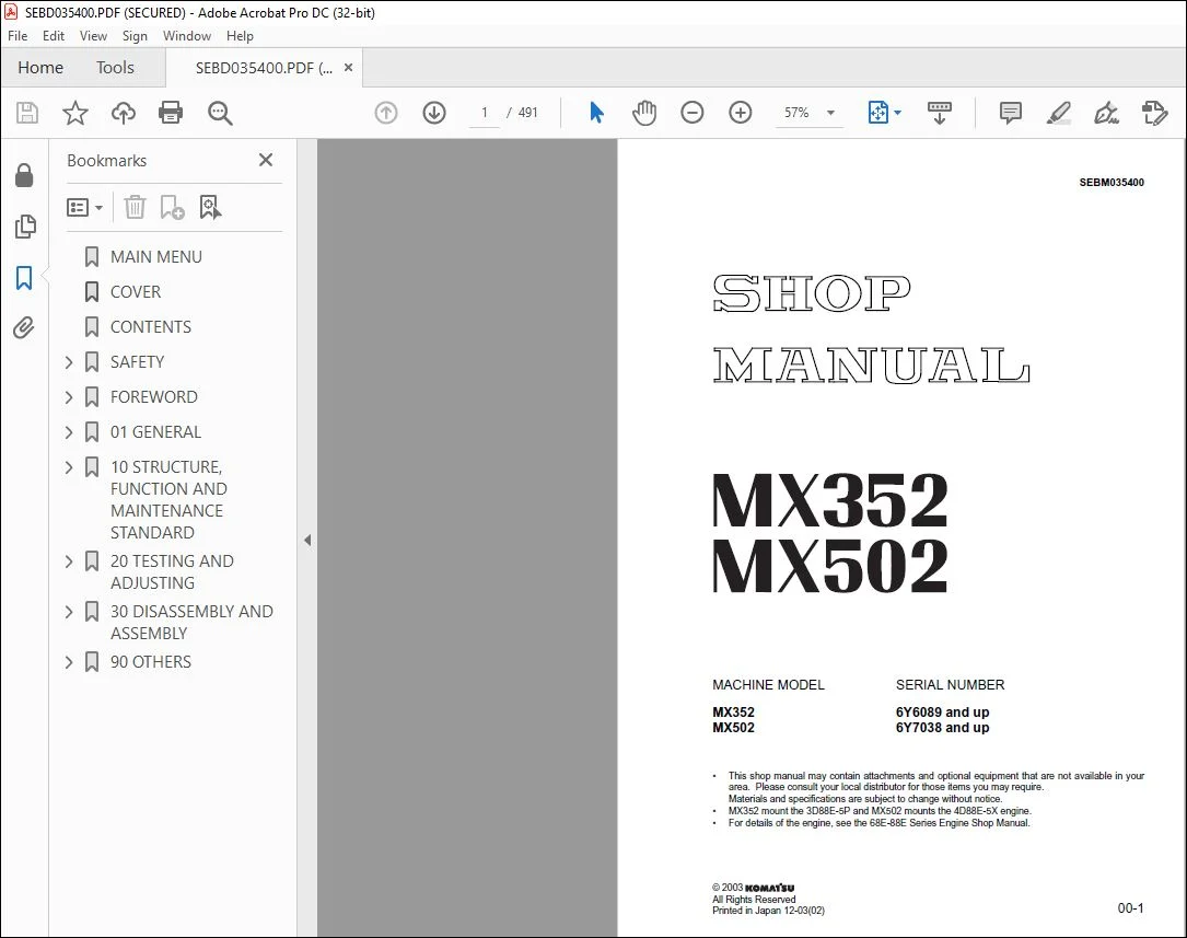
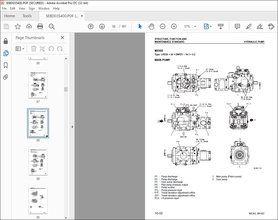
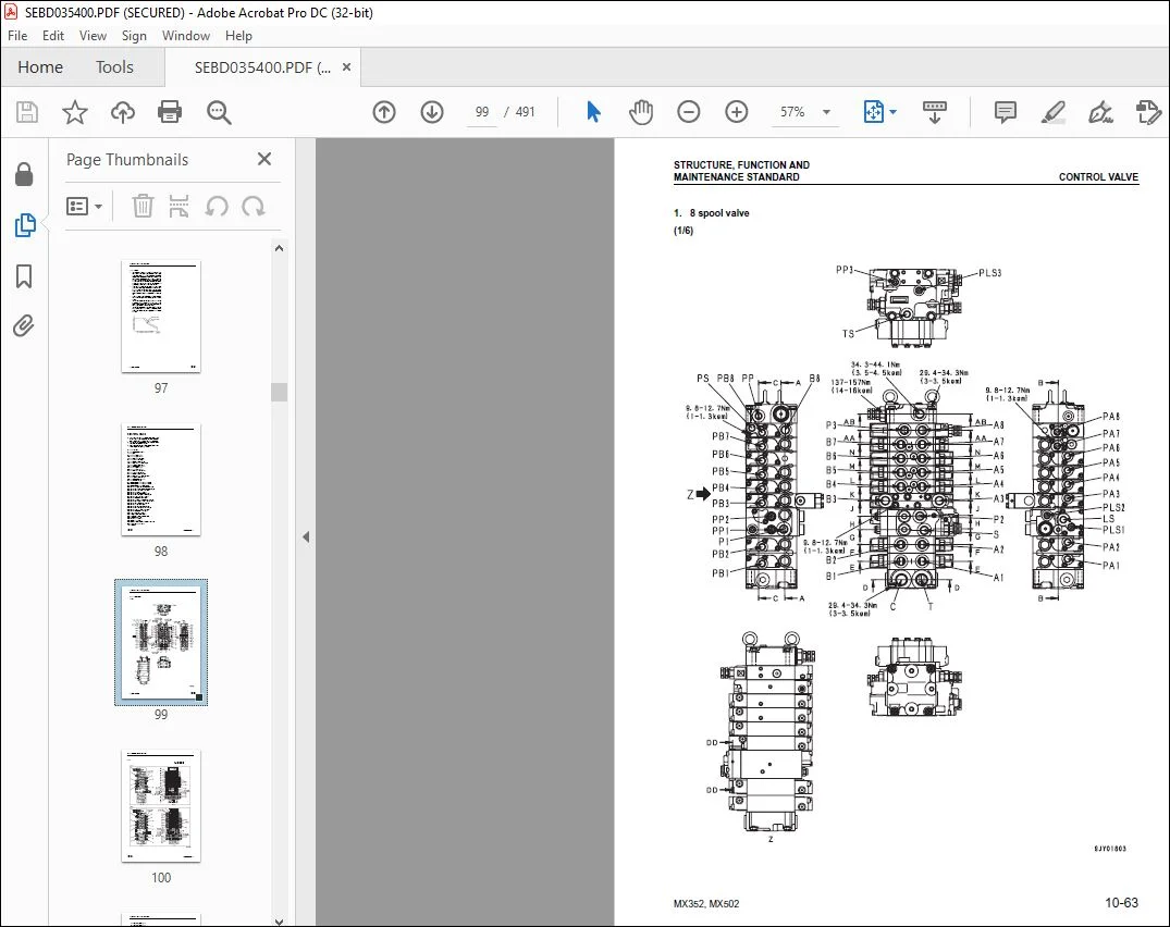
Komatsu MX352 MX502 Hydraulic Excavator Shop Manual SEBM035400 – PDF DOWNLOAD
Original price was: $89.00.$29.95Current price is: $29.95.
Komatsu MX352 MX502 Hydraulic Excavator Shop Manual SEBM035400 – PDF DOWNLOAD
SERIAL NUMBER
6Y6089 and up
6Y7038 and up
Description
Komatsu MX352 MX502 Hydraulic Excavator Shop Manual SEBM035400 – PDF DOWNLOAD
IMAGES PREVIEW OF THE MANUAL:
DESCRIPTION:
Komatsu MX352 MX502 Hydraulic Excavator Shop Manual SEBM035400 – PDF DOWNLOAD
SAFETY
SAFETY NOTICE
IMPORTANT SAFETY NOTICE
- Proper service and repair is extremely important for safe machine operation. The service and repair techniques recommended by Komatsu and described in this manual are both effective and safe. Some of these techniques require the use of tools specially designed by Komatsu for the specific purpose.
- To prevent injury to workers, the symbol ¤ is used to mark safety precautions in this manual. The cautions accompanying these symbols should always be followed carefully. If any dangerous situation arises or may possibly arise, first consider safety, and take the necessary actions to deal with the situation.
GENERAL PRECAUTIONS
Mistakes in operation are extremely dangerous. Read the Operation and Maintenance Manual carefully
BEFORE operating the machine
1. Before carrying out any greasing or repairs, read all the precautions given on the decals which are fixed to the machine.
2. When carrying out any operation, always wear safety shoes and helmet. Do not wear loose work clothes, or clothes with buttons missing.
• Always wear safety glasses when hitting parts with a hammer.
• Always wear safety glasses when grinding parts with a grinder, etc.
3. If welding repairs are needed, always have a trained, experienced welder carry out the work. When carrying out welding work, always wear welding gloves, apron, hand shield, cap and other clothes suited for welding work.
4. When carrying out any operation with two or more workers, always agree on the operating procedure before starting. Always inform your fellow workers before starting any step of the operation. Before starting work, hang UNDER REPAIR signs on the controls in the operator’s compartment.
5. Keep all tools in good condition and learn the correct way to use them.
6. Decide a place in the repair workshop to keep tools and removed parts. Always keep the tools and parts in their correct places. Always keep the work area clean and make sure that there is no dirt or oil on the floor. Smoke only in the areas provided for smoking. Never smoke while working.
PREPARATIONS FOR WORK
7. Before adding oil or making any repairs, park the machine on hard, level ground, and block the wheels or tracks to prevent the machine from moving.
8. Before starting work, lower blade, ripper, bucket or any other work equipment to the ground. If this is not possible, insert the safety pin or use blocks to prevent the work equipment from falling. In addition, be sure to lock all the control levers and hang warning signs on them.
9. When disassembling or assembling, support the machine with blocks, jacks or stands before starting work. 10.Remove all mud and oil from the steps or other places used to get on and off the machine. Always use the handrails, ladders or steps when getting on or off the machine. Never jump on or off the machine. If it is impossible to use the handrails, ladders or steps, use a stand to provide safe footing. SAFETY SAFETY NOTICE 00-4 PRECAUTIONS DURING WORK
11.When removing the oil filler cap, drain plug or hydraulic pressure measuring plugs, loosen them slowly to prevent the oil from spurting out. Before disconnecting or removing components of the oil, water or air circuits, first remove the pressure completely from the circuit.
12.The water and oil in the circuits are hot when the engine is stopped, so be careful not to get burned. Wait for the oil and water to cool before carrying out any work on the oil or water circuits.
13.Before starting work, remove the leads from the battery. Always remove the lead from the negative (–) terminal first.
14.When raising heavy components, use a hoist or crane. Check that the wire rope, chains and hooks are free from damage. Always use lifting equipment which has ample capacity. Install the lifting equipment at the correct places. Use a hoist or crane and operate slowly to prevent the component from hitting any other part. Do not work with any part still raised by the hoist or crane.
15.When removing covers which are under internal pressure or under pressure from a spring, always leave two bolts in position on opposite sides. Slowly release the pressure, then slowly loosen the bolts to remove.
16.When removing components, be careful not to break or damage the wiring. Damaged wiring may cause electrical fires.
17.When removing piping, stop the fuel or oil from spilling out. If any fuel or oil drips onto the floor, wipe it up immediately. Fuel or oil on the floor can cause you to slip, or can even start fires.
18.As a general rule, do not use gasoline to wash parts. In particular, use only the minimum of gasoline when washing electrical parts.
19.Be sure to assemble all parts again in their original places. Replace any damaged parts with new parts. • When installing hoses and wires, be sure that they will not be damaged by contact with other parts when the machine is being operated.
20.When installing high pressure hoses, make sure that they are not twisted. Damaged tubes are dangerous, so be extremely careful when installing tubes for high pressure circuits. Also, check that connecting parts are correctly installed.
21.When assembling or installing parts, always use the specified tightening torques. When installing protective parts such as guards, or parts which vibrate violently or rotate at high speed, be particularly careful to check that they are installed correctly.
22.When aligning two holes, never insert your fingers or hand. Be careful not to get your fingers caught in a hole
. 23.When measuring hydraulic pressure, check that the measuring tool is correctly assembled before taking any measurements.
24.Take care when removing or installing the tracks of track-type machines. When removing the track, the track separates suddenly, so never let anyone stand at either end of the track.
FOREWORD
GENERAL
- This shop manual has been prepared as an aid to improve the quality of repairs by giving the serviceman an
accurate understanding of the product and by showing him the correct way to perform repairs and make judgements.
Make sure you understand the contents of this manual and use it to full effect at every opportunity. - This shop manual mainly contains the necessary technical information for operations performed in a service
workshop. For ease of understanding, the manual is divided into the following chapters; these chapters are further
divided into the each main group of components
STRUCTURE AND FUNCTION
This section explains the structure and function of each component. It serves not only to give an understanding
of the structure, but also serves as reference material for troubleshooting.
In addition, this section may contain hydraulic circuit diagrams, electric circuit diagrams, and maintenance
standards.
TESTING AND ADJUSTING
This section explains checks to be made before and after performing repairs, as well as adjustments to
be made at completion of the checks and repairs.
Troubleshooting charts correlating “Problems” with “Causes” are also included in this section.
DISASSEMBLY AND ASSEMBLY
This section explains the procedures for removing, installing, disassembling and assembling each component,
as well as precautions for them.
MAINTENANCE STANDARD
This section gives the judgment standards for inspection of disassembled parts.
The contents of this section may be described in STRUCTURE AND FUNCTION.
OTHERS
This section mainly gives hydraulic circuit diagrams and electric circuit diagrams.
In addition, this section may give the specifications of attachments and options together
TABLE OF CONTENTS:
Komatsu MX352 MX502 Hydraulic Excavator Shop Manual SEBM035400 – PDF DOWNLOAD
MAIN MENU 0
COVER 1
CONTENTS 2
SAFETY 3
SAFETY NOTICE 3
FOREWORD 5
GENERAL 5
HOW TO READ THE SHOP MANUAL 6
HOISTING INSTRUCTIONS 7
METHOD OF DISASSEMBLING, CONNECTING PUSH-PULL TYPE COUPLER 8
COATING MATERIALS 10
STANDARD TIGHTENING TORQUE 12
ELECTRIC WIRE CODE 15
CONVERSION TABLE 16
UNITS 22
01 GENERAL 23
SPECIFICATION DIMENSION DRAWING 24
WORKING RANGE DRAWING 25
SPECIFICATIONS 26
WEIGHT TABLE 32
LUBRICANTS, FUEL AND COOLANT SPECIFICATIONS 34
10 STRUCTURE, FUNCTION AND MAINTENANCE STANDARD 37
PTO 38
COOLING SYSTEM 40
POWER TRAIN 42
SWING CIRCLE 43
SWING MACHINERY 44
TRACK FRAME 48
IDLER CUSHION 49
IDLER 50
TRACK ROLLER 52
CARRIER ROLLER 54
SPROCKET 55
TRACK SHOE 56
HYDRAULIC COMPONENTS LAYOUT DRAWING 64
HYDRAULIC TANK 66
CENTER SWIVEL JOINT 69
TRAVEL MOTOR 71
HYDRAULIC CYLINDER 79
SOLENOID VALVE 83
MULTI-CONTROL VALVE 86
HYDRAULIC PUMP 87
CONTROL VALVE 98
CLSS112
OPERATION FOR EACH FUNCTION AND VALVE116
SWING MOTOR138
PPC VALVE147
WORK EQUIPMENT155
DIMENSIONS OF EACH PART OF WORK EQUIPMENT158
FLOOR164
AIR CONDITIONER165
ENGINE CONTROL166
ELECTRIC CONTROL SYSTEM168
COMPONENT PARTS OF SYSTEM173
MONITOR SYSTEM174
MONITOR PANEL175
SENSORS177
20 TESTING AND ADJUSTING179
STANDARD VALUE TABLE FOR ENGINE RELATED PARTS180
STANDARD VALUE TABLE FOR CHASSIS RELATED PARTS182
TESTING AND ADJUSTING197
LIST OF TESTING, ADJUSTING, AND TROUBLESHOOTING TOOLS198
MEASURING ENGINE SPEED200
MEASUREMENT OF EXHAUST GAS COLOR201
ADJUSTING VALVE CLEARANCE202
MEASURING COMPRESSION PRESSURE205
MEASURING ENGINE OIL PRESSURE206
TESTING AND ADJUSTING FUEL INJECTION TIMING207
TESTING AND ADJUSTING ALTERNATOR BELT TENSION209
ADJUSTING FUEL CONTROL LEVER210
TESTING WEAR OF SPROCKET211
TESTING AND ADJUSTING TRACK SHOE TENSION212
MEASURING AND ADJUSTING OIL PRESSURES IN WORK EQUIPMENT, TRAVEL, BOOM SWING, SWING, AND BLADE CIRCUITS213
MEASURING AND ADJUSTING LS DIFFERENTIAL PRESSURE217
ADJUSTING PC VALVE221
MEASURING AND ADJUSTING CONTROL PUMP CIRCUIT OIL PRESSURE222
MEASURING SOLENOID VALVE OUTPUT PRESSURE224
MEASURING PPC VALVE OUTPUT PRESSURE226
ADJUSTING PPC VALVE229
MEASURING SWING HOLDING BRAKE RELEASE PRESSURE230
TESTING AND ADJUSTING TRAVEL DEVIATION231
MEASUREMENT OF OIL LEAKAGE FROM WORK EQUIPMENT CYLINDER233
BLEEDING AIR FROM EACH PART235
RELEASING RESIDUAL PRESSURE FROM HYDRAULIC CIRCUIT238
RELEASING RESIDUAL PRESSURE FROM HYDRAULIC TANK238
PRESSURIZING HYDRAULIC TANK239
INSPECTION PROCEDURES FOR DIODE240
TROUBLESHOOTING241
POINTS TO REMEMBER WHEN TROUBLESHOOTING242
SEQUENCE OF EVENTS IN TROUBLESHOOTING243
POINTS TO REMEMBER WHEN CARRYING OUT MAINTENANCE244
CHECKS BEFORE TROUBLESHOOTING252
CLASSIFICATION AND PROCEDURES OF TROUBLESHOOTING253
TYPES AND LOCATIONS OF CONNECTORS256
CONNECTOR ARRANGEMENT DIAGRAM262
CONNECTION TABLE FOR CONNECTOR PIN NUMBERS270
T-ADAPTER – BOXES AND T-ADAPTER TABLE292
TROUBLESHOOTING OF ELECTRICAL SYSTEM (E MODE)295
BEFORE STARTING E-MODE TROUBLESHOOTING296
INFORMATION CONTAINED IN TROUBLESHOOTING TABLE297
E-1 ENGINE DOES NOT START298
E-2 ENGINE DOES NOT STOP306
E-3 WHEN WORK EQUIPMENT LOCK (PPC BASIC PRESSURE LOCK) LEVER IS SET IN LOCK POSITION, WORK EQUIPMENT STILL MOVES310
E-4 WINDSHIELD WIPER DOES NOT OPERATE314
E-5 WINDSHIELD WASHER DOES NOT OPERATE316
E-6 TRAVEL ALARM DOES NOT SOUND320
TROUBLESHOOTING OF HYDRAULIC AND MECHANICAL SYSTEM (H MODE)323
INFORMATION CONTAINED IN TROUBLESHOOTING TABLE324
H-1 SPEED OR POWER OF WHOLE WORK EQUIPMENT, TRAVEL, SWING, AND BLADE IS LOW325
H-2 ENGINE SPEED LOWERS EXTREMELY OR ENGINE STALLS329
H-3 WHOLE WORK EQUIPMENT, TRAVEL SYSTEM, SWING SYSTEM, AND BLADE DO NOT WORK330
H-4 ABNORMAL SOUND COMES OUT FROM AROUND HYDRAULIC PUMP333
H-5 FINE CONTROL PERFORMANCE OR RESPONSE IS LOW333
H-6 SPEED OR POWER OF BOOM IS LOW334
H-7 SPEED OR POWER OF ARM IS LOW335
H-8 SPEED OR POWER OF BUCKET IS LOW336
H-9 SPEED OR POWER OF BOOM SWING IS LOW337
H-10 WORK EQUIPMENT DOES NOT MOVE SINGLY338
H-11 WORK EQUIPMENT HYDRAULIC DRIFT IS LARGE339
H-12 TIME LAG OF WORK EQUIPMENT IS LARGE340
H-13 IN COMPOUND OPERATION OF WORK EQUIPMENT, SPEED OF PART LOADED MORE IS LOW340
H-14 MACHINE DEVIATES DURING TRAVEL341
H-15 TRAVEL SPEED OR TRAVEL POWER IS LOW (WHILE WORK EQUIPMENT IS NORMAL)343
H-16 MACHINE IS NOT STEERED WELL OR STEERING POWER IS LOW344
H-17 TRAVEL SPEED DOES NOT CHANGE345
H-18 TRAVEL MOTOR DOES NOT WORK346
H-19 SPEED OR POWER OF SWING IS LOW348
H-20 MACHINE DOES NOT SWING350
H-21 SWING ACCELERATION PERFORMANCE IS LOW352
H-22 MACHINE OVERRUNS WHEN IT STOPS SWINGING354
H-23 LARGE SHOCK IS MADE WHEN MACHINE STOPS SWINGING355
H-24 WHEN UPPER STRUCTURE STOPS SWINGING, IT MAKES LARGE SOUND355
H-25 HYDRAULIC DRIFT OF SWING IS LARGE356
H-26 SPEED OR POWER OF BLADE IS LOW357
H-27 BLADE DOES NOT MOVE358
H-28 HYDRAULIC DRIFT OF BLADE IS LARGE358
TROUBLESHOOTING OF MONITOR PANEL SYSTEM (M MODE)359
BEFORE STARTING M-MODE TROUBLESHOOTING360
INFORMATION CONTAINED IN TROUBLESHOOTING TABLE361
SYSTEM DIAGRAM RELATED TO MONITOR PANEL362
M-1 WHEN STARTING SWITCH IS TURNED ON, ANY ITEM DOES NOT OPERATE364
M-2 WHEN STARTING SWITCH IS TURNED ON, SOME ITEMS DO NOT OPERATE366
M-3 ALARM BUZZER IS ABNORMAL367
M-4 ENGINE OIL PRESSURE CAUTION IS TURNED ON369
M-5 CHARGE LEVEL CAUTION IS TURNED ON370
M-6 PREHEATING SYSTEM DOES NOT OPERATE OR PREHEATER DOES NOT BECOME HOT374
M-7 COOLANT TEMPERATURE GAUGE IS ABNORMAL376
M-8 FUEL LEVEL GAUGE IS ABNORMAL381
M-9 SERVICE METER DOES NOT OPERATE WHILE ENGINE IS RUNNING385
M-10 2ND TRAVEL SPEED IS NOT SELECTED387
M-11 WORKING LAMP DOES NOT LIGHT UP392
TROUBLESHOOTING OF ENGINE (S MODE)395
METHOD OF USING TROUBLESHOOTING CHARTS396
S-1 STARTING PERFORMANCE IS POOR (STARTING ALWAYS TAKES TIME)400
S-2 ENGINE DOES NOT START402
S-3 ENGINE DOES NOT PICK UP SMOOTHLY (FOLLOW-UP IS POOR)405
S-4 ENGINE STOPS DURING OPERATIONS406
S-5 ENGINE DOES NOT ROTATE SMOOTHLY (HUNTING)407
S-6 ENGINE LACKS OUTPUT OR LACKS POWER408
S-7 EXHAUST SMOKE IS BLACK (INCOMPLETE COMBUSTION)409
S-8 OIL CONSUMPTION IS EXCESSIVE OR EXHAUST SMOKE IS BLUE410
S-9 OIL BECOMES CONTAMINATED QUICKLY411
S-10 FUEL CONSUMPTION IS EXCESSIVE412
S-11 OIL IS IN COOLING WATER, OR WATER SPURTS BACK, OR WATER LEVEL GOES DOWN413
S-12 OIL PRESSURE CAUTION LAMP LIGHTS UP (DROP IN OIL PRESSURE)414
S-13 OIL LEVEL RISES (WATER, FUEL IN OIL)415
S-14 WATER TEMPERATURE BECOMES TOO HIGH (OVERHEATING)416
S-15 ABNORMAL NOISE IS MADE417
S-16 VIBRATION IS EXCESSIVE418
30 DISASSEMBLY AND ASSEMBLY419
HOW TO READ THIS MANUAL420
PRECAUTIONS WHEN PERFORMING OPERATION422
SPECIAL TOOL LIST424
SKETCHES OF SPECIAL TOOLS428
REMOVAL AND INSTALLATION OF RADIATOR AND HYDRAULIC OIL COOLER429
REMOVAL AND INSTALLATION OF ENGINE AND HYDRAULIC PUMP438
REMOVAL AND INSTALLATION OF TRACK SHOE445
DISASSEMBLY AND ASSEMBLY OF IDLER446
DISASSEMBLY AND ASSEMBLY OF RECOIL SPRING448
DISASSEMBLY AND ASSEMBLY OF TRACK ROLLER451
DISASSEMBLY AND ASSEMBLY OF CARRIER ROLLER 453
REMOVAL AND INSTALLATION OF CENTER SWIVEL JOINT454
DISASSEMBLY AND ASSEMBLY OF CENTER SWIVEL JOINT457
REMOVAL AND INSTALLATION OF FLOOR FRAME ASSEMBLY459
REMOVAL AND INSTALLATION OF SWING MOTOR AND SWING MACHINERY463
DISASSEMBLY AND ASSEMBLY OF SWING MOTOR AND SWING MACHINERY464
REMOVAL AND INSTALLATION OF WORK EQUIPMENT470
REMOVAL AND INSTALLATION OF REVOLVING FRAME472
REMOVAL AND INSTALLATION OF SWING CIRCLE474
DISASSEMBLY AND ASSEMBLY OF CONTROL VALVE475
DISASSEMBLY AND ASSEMBLY OF HYDRAULIC CYLINDER ASSEMBLY476
REMOVAL AND INSTALLATION OF AIR CONDITIONER UNIT480
90 OTHERS483
HYDRAULIC CIRCUIT DIAGRAM MX352484
HYDRAULIC CIRCUIT DIAGRAM MX502485
HYDRAULIC CIRCUIT DIAGRAM (Additional attachment circuit) MX502486
ELECTRICAL CIRCUIT DIAGRAM MX352 (1/2)487
ELECTRICAL CIRCUIT DIAGRAM MX352 (2/2)488
ELECTRICAL CIRCUIT DIAGRAM MX502 (1/2)489
Questions? Email us: [email protected]
https://vimeo.com/743313872
PLEASE NOTE:
- This is the same manual used by the DEALERSHIPS to SERVICE your vehicle.
- The manual can be all yours – Once payment is complete, you will be taken to the download page from where you can download the manual. All in 2-5 minutes time!!
- Need any other service / repair / parts manual, please feel free to contact us at heydownloadss @gmail.com . We may surprise you with a nice offer
S.M



