
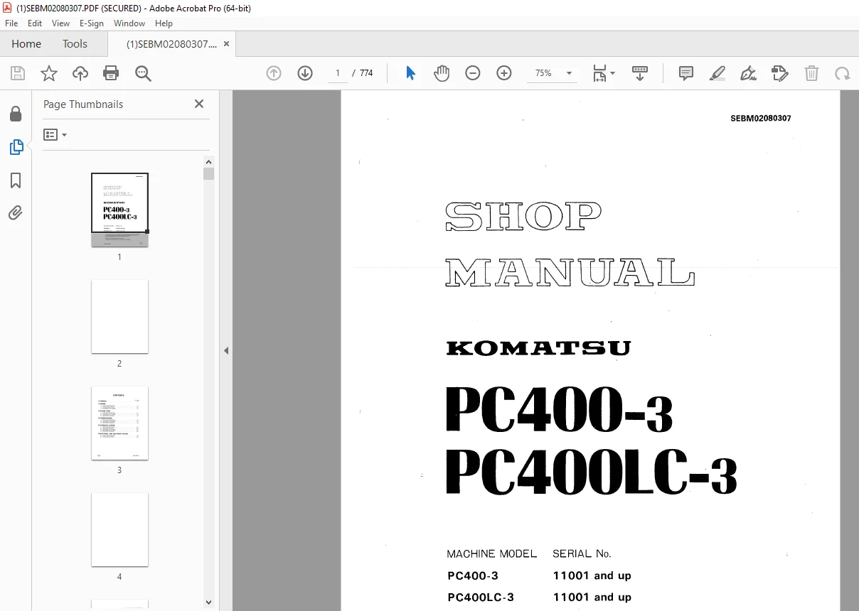
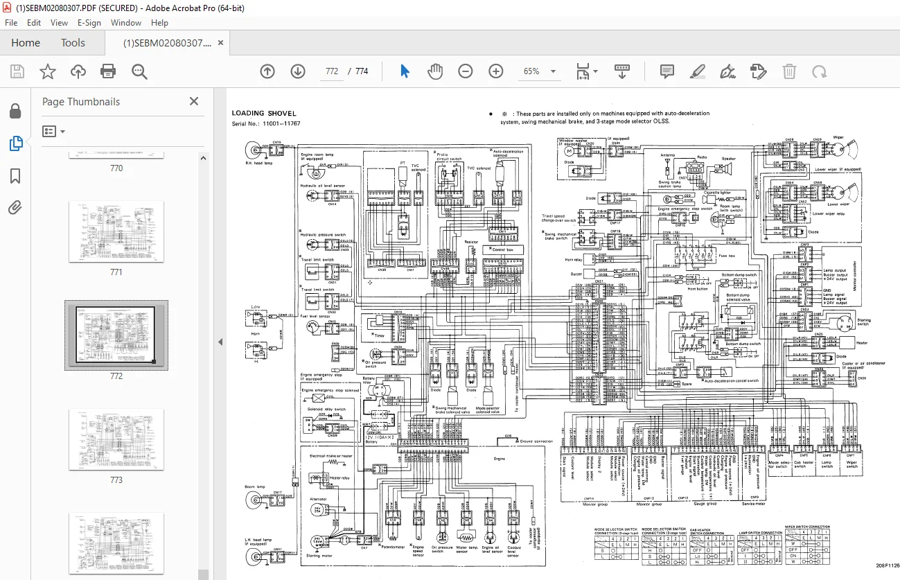
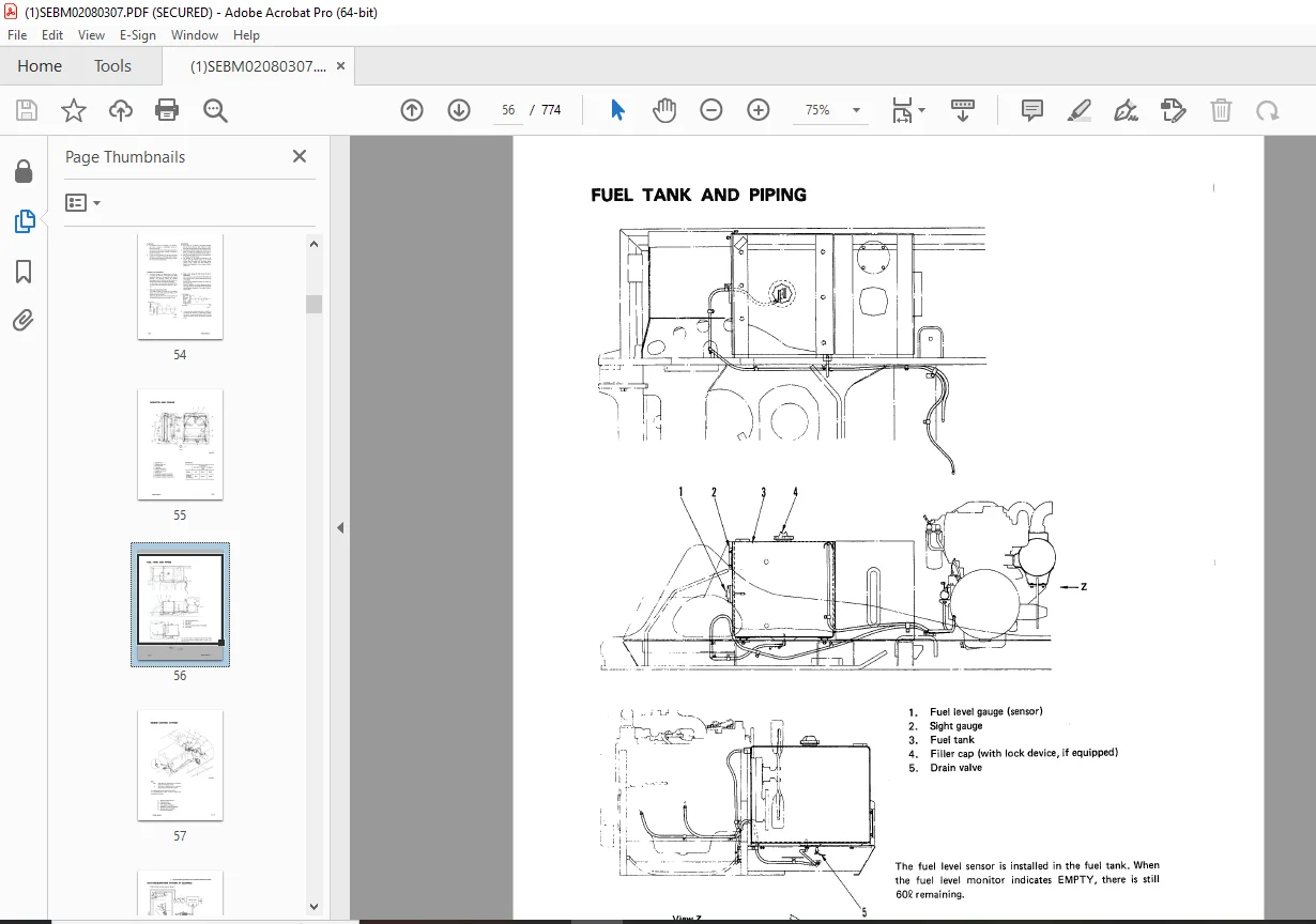
Komatsu PC1000-1,PC1000LC-1,PC1000SE-1,PC1000SP-1 Hydraulic Excavator Shop Manual PDF
$32.95
Komatsu PC1000-1,PC1000LC-1,PC1000SE-1,PC1000SP-1 Hydraulic Excavator Shop Manual SEBM021N0107 – PDF DOWNLOAD
SERIAL NUMBER
- PC1000-1 10001 and up
- PC1000LC-1 10001 and up
- PC10000SE-1 10001 and up
- PC10000SP-1 10001 and up
Description
Komatsu PC1000-1,PC1000LC-1,PC1000SE-1,PC1000SP-1 Hydraulic Excavator Shop Manual SEBM021N0107 – PDF DOWNLOAD
FILE DETAILS:
Komatsu PC1000-1,PC1000LC-1,PC1000SE-1,PC1000SP-1 Hydraulic Excavator Shop Manual SEBM021N0107 – PDF DOWNLOAD
Language : English
Pages : 750
Downloadable : Yes
File Type : PDF
IMAGES PREVIEW OF THE MANUAL:
TABLE OF CONTENTS:
Komatsu PC1000-1,PC1000LC-1,PC1000SE-1,PC1000SP-1 Hydraulic Excavator Shop Manual SEBM021N0107 – PDF DOWNLOAD
SERIAL NUMBER
- PC1000-1 10001 and up
- PC1000LC-1 10001 and up
- PC10000SE-1 10001 and up
- PC10000SP-1 10001 and up
MAIN MENU . 0
CONTENTS 2
LIST OF REVISED PAGES . 3
SAFETY NOTICE . 8
FOREWORD 10
HOW TO READ THE SHOP MANUAL . 11
HOISTING INSTRUCTIONS . 12
WIRE ROPES 12
COATING MATERIALS . 13
STANDARD TIGHTENING TORQUE 15
STANDARD TIGHTENING TORQUES OF BOLTS AND NUTS . 15
TIGHTENING TORQUE OF HOSE NUTS 15
TIGHTENING TORQUE OF SPLIT FLANGE BOLTS . 15
TIGHTENING TORQUE OF O-RING BOSS CONNECTOR 16
TIGHTENING TORQUE OF O-RING BOSS CONNECTOR 16
TIGHTENING TORQUES OF FLARE NUT . 16
TIGHTENING TORQUE FOR 102 SERIES ENGINE (BOLT AND NUTS) . 17
TIGHTENING TORQUE FOR 102 SERIES ENGINE (EYE JOINTS) 17
TIGHTENING TORQUE FOR 102 SERIES ENGINE (TAPERED SCREWS) 17
ELECTRIC WIRE CODE 18
CLASSIFICATION BY THICKNESS . 18
CLASSIFICATION BY COLOR AND CODE 18
CONVERSION TABLE 19
METHOD OF USING THE CONVERSION TABLE 19
Millimeters to Inches . 20
Kilogram to Pound . 20
Liter to U.S. Gallon 21
Liter to U.K. Gallon 21
kgm to ft. lb . 22
kg/cm2 to lb/in2 23
Temperature . 24
10 ENGINE . 28
11 STRUCTURE AND FUNCTION . 28
PTO (Power Take-Off) 29
PTO LUBRICATION SYSTEM 30
AUTO-DECELERATION SYSTEM 31
OPERATION TABLE . 34
1. DECELERATOR CYLINDER . 35
2. SOLENOID VALVE . 36
OPERATION . 37
1. SOL A excited (engine running, control levers at NEUTRAL) 37
2. SOL A, B deactivated (engine running, control levers at NEUTRAL) . 37
3. SOL B excited (engine running, control levers operated) 37
3. OIL PRESSURE SWITCH 38
4. AUTO-DECELERATOR SELECTOR SWITCH . 38
12 TESTING AND ADJUSTING 39
STANDARD FOR TESTING AND ADJUSTING 40
TESTING AND ADJUSTING TOOL LIST . 42
ADJUSTING VALVE CLEARANCE . 43
MEASURING COMPRESSION PRESSURE 44
MEASURING BLOW-BY PRESSURE 45
TESTING AND ADJUSTING FUEL INJECTION TIMING . 46
ADJUSTING FUEL CONTROL LEVER 49
ADJUSTING AUTO-DECELERATION SYSTEM 52
MEASURING EXHAUST GAS COLOR . 54
13 DISASSEMBLY AND ASSEMBLY . 55
STARTING MOTOR 56
REMOVAL . 56
INSTALLATION 56
ALTERNATOR 56
REMOVAL . 56
INSTALLATION 56
ENGINE OIL COOLER . 58
REMOVAL . 58
INSTALLATION 58
WATER PUMP 58
REMOVAL . 58
INSTALLATION 58
FUEL INJECTION PUMP . 60
REMOVAL 60
INSTALLATION 60
NOZZLE HOLDER . 62
REMOVAL . 62
INSTALLATION 62
TURBOCHARGER 64
REMOVAL . 64
INSTALLATION 64
CYLINDER HEAD . 66
REMOVAL . 66
INSTALLATION Serial No.: 10001 – 10371 77
INSTALLATION Serial No.: 10372 and up . 83
HYDRAULIC OIL COOLER 89
REMOVAL . 89
INSTALLATION 89
RADIATOR 89
REMOVAL . 89
INSTALLATION 89
ENGINE, PTO, HYDRAULIC PUMP . 91
REMOVAL . 91
INSTALLATION 93
PTO . 99
REMOVAL . 99
INSTALLATION 99
DISASSEMBLY .101
ASSEMBLY 101
AUTO-DECELERATION CYLINDER 105
REMOVAL Serial No.: 10001 – 10371 .105
INSTALLATION Serial No.: 10001 – 10371 105
REMOVAL Serial No.: 10372 and up 105
INSTALLATION Serial No.: 10372 and up 105
14 MAINTENANCE STANDARD .107
PTO (Power Take-Off) 108
20 POWER TRAIN 109
21 STRUCTURE AND FUNCTION .109
POWER TRAIN .110
TRAVEL AND BRAKE SYSTEM .111
1. TRAVEL CONTROL CIRCUIT SCHEMATICS 111
2. TRAVEL CONTROL CIRCUIT .112
3. STRAIGHT-TRAVEL SYSTEM .113
4. CENTER SWIVEL JOINT 118
5. TRAVEL MOTOR AND BRAKE VALVE .119
6. FINAL DRIVE 131
SWING SYSTEM 133
1. SWING HYDRAULIC CIRCUIT SCHEMATICS .133
2. SWING HYDRAULIC CIRCUIT 134
3. SWING PUMP .135
4. SWING CONTROL VALVE 138
5. SWING MOTOR (WITH MECHANICAL BRAKE) AND SAFETY VALVE .140
6. SWING BRAKE (AUTOMATIC) AND SWING PARKING BRAKE (MANUAL) .144
7. FREE SWING SYSTEM 148
8. SWING MACHINERY 151
9. SWING CIRCLE .153
23 DISASSEMBLY AND ASSEMBLY .154
CENTER SWIVEL JOINT ASSEMBLY 155
REMOVAL .155
INSTALLATION 155
DISASSEMBLY .157
ASSEMBLY 157
TRAVEL MOTOR, BRAKE VALVE .159
REMOVAL .159
INSTALLATION 159
TRAVEL MOTOR 161
DISASSEMBLY .161
ASSEMBLY 167
ASSEMBLY OF END COVER ASSEMBLY 167
1. Servo piston assembly 167
2. Valve plate 167
ASSEMBLY OF BRAKE VALVE ASSEMBLY 167
3. Suction valve 167
4. Safety valve assembly 167
5. Counterbalance valve .169
ASSEMBLY OF MOTOR .169
6. Bearing outer race .169
7. Shaft assembly .169
8. Disc, plate 171
9. Piston, retainer .171
10. Brake piston assembly .173
11. Cylinder block 173
12. Spring 173
13. Motor case 173
14. End cover assembly 173
15. Block .173
16. Measuring rotation torque .173
17. Measuring brake torque 175
FINAL DRIVE ASSEMBLY 177
REMOVAL .177
INSTALLATION 177
DISASSEMBLY .179
1. Case assembly 179
2. Coupling, pinion gear 179
3. Case, gear assembly 179
4. Carrier assembly (small) .179
5. Ring gear (small) 181
8. Carrier assembly (large) .181
7. Shaft 181
8. Ring gear, housing assembly 181
9. Case assembly 181
ASSEMBLY 183
1. Housing 183
2. Case assembly 183
3. Bearing 183
4. Ring gear, housing assembly 183
5. Preload adjustment, retainer .183
6. Shaft 185
7. Carrier assembly (large) .185
8. Carrier assembly (small) .187
9. Ring gear (small) 187
10. Case and gear assembly 187
11. Pinion gear .189
12. Case assembly .189
SPROCKET 191
REMOVAL .191
INSTALLATION 191
SWING PUMP 193
REMOVAL .193
INSTALLATION 193
DISASSEMBLY .195
ASSEMBLY 199
ASSEMBLY OF PUMP SUBASSEMBLY 199
1. Cradle, piston assembly 199
2. Cylinder block .199
3. Shaft assembly .201
4. Servo piston .203
5. Pump subassembly .205
6. Adjusting end play of bearing 205
7. End cap 205
8. Servo piston cap .205
9. Impeller .207
10. Servo and CO-NC valves 209
11. Rear pump assembly 209
CO-NC VALVE ASSEMBLY 211
REMOVAL .211
INSTALLATION 211
SERVO VALVE .211
REMOVAL .211
INSTALLATION 211
PPC VALVE .213
REMOVAL .213
INSTALLATION 213
DISASSEMBLY .213
ASSEMBLY 213
SWING CONTROL VALVE .215
REMOVAL .215
INSTALLATION 215
MAIN RELIEF VALVE .215
REMOVAL .215
INSTALLATION 215
SWING CONTROL VALVE .219
DISASSEMBLY .217
ASSEMBLY 219
FRONT SWING MOTOR .221
REMOVAL .221
INSTALLATION 221
REAR SWING MOTOR 221
REMOVAL .221
INSTALLATION 221
SWING MOTOR ASSEMBLY 227
DISASSEMBLY .223
ASSEMBLY 227
1. Outer race .227
2. Shaft assembly .227
3. Belleville spring, spacer, bearing .227
4. Spacer .227
5. Cover 227
6. Plate, disc 227
7. Brake piston .229
8. Piston, shaft 229
9. Spring .229
10. Cylinder block 229
11. Valve plate .229
12. Belleville spring .229
13. Check valve .229
14. Relief valve 229
15. Valve case assembly 229
16. Inspection of rotating torque of drive shaft 229
REVOLVING FRAME .231
REMOVAL .231
INSTALLATION 231
SWING CIRCLE 233
REMOVAL .233
INSTALLATION 233
FRONT SWING MACHINERY .235
REMOVAL .235
INSTALLATION 235
REAR SWING MACHINERY 237
REMOVAL .237
INSTALLATION 237
SWING MACHINERY .239
DISASSEMBLY .239
1. Cover 239
2. Coupling .239
3. Ring gear 239
4. Thrust washer 239
5. Sungear 239
6. Carrier assembly .239
7. Thrust washer 239
8. Bolt, plate 239
9. Gear assembly 239
10. Shaft .239
11. Spacer 241
12. Snap ring, bearing 241
13. Oil seal 241
DISASSEMBLY OF CARRIER ASSEMBLY .241
14. Shaft .241
15. Gear assembly .241
SWING MACHINERY 243
DISASSEMBLY Serial No. 10001-10077 239
1. Cover 239
2. Coupling .239
3. Ring gear 239
4. Thrust washer 239
5. Sungear 239
6. Carrier assembly .239
7. Thrust washer 239
8. Bolt, plate 239
9. Gear assembly 239
10. Shaft .239
11. Spacer 241
12. Snap ring, bearing 241
13. Oil seal 241
14. Shaft .241
15. Gear assembly .241
ASSEMBLY Serial No. 10001-10077 .243
1. Gear assembly 243
2. Shaft 243
3. Oil seal .243
4. Bearing, snap ring .243
6. Shaft 243
6. Spacer .243
7. Bearing 245
8. Gear assembly 245
9. Plate, bolt 245
10. Thrust washer .245
11. Carrier assembly, sun gear 245
12. Thrust washer .247
13. Ring gear .247
14. Coupling 247
15. Cover .247
16. Refilling with oil 247
DISASSEMBLY Serial No. 10078 and up .249
1. Oil filler .249
2. Cover 249
3. No. 1 sun gear .249
4. No. 1 carrier assembly .249
5. Ring gear 250
6. No. 2 carrier assembly .251
7. Swing pinion .252
8. Spacer .253
9. Oil seal, bearing 253
10. Bearing .253
ASSEMBLY Serial No. 10078 and up 254
1. Bearing, oil seal 254
2. Swing pinion .254
3. Retainer .255
4. No. 2 carrier assembly .255
5. Ring gear 257
6. No. 1 carrier assembly .257
7. No. 1 sun gear .258
8. Cover 259
9. Oil filler .260
24 MAINTENANCE STANDARD .261
TRAVEL MOTOR AND BRAKE VALVE 262
TRAVEL RELIEF VALVE .264
TRAVEL SHUTTLE VALVE 265
STRAIGHT-TRAVEL VALVE .266
FINAL DRIVE .267
SWING CONTROL VALVE .268
JET SENSOR 269
CONNECTION VALVE 270
SWING MOTOR .271
SWING MACHINERY .272
SWING CIRCLE 274
30 UNDERCARRIAGE 275
31 STRUCTURE AND FUNCTION .275
TRACK FRAME .276
IDLER CUSHION .279
IDLER .283
TRACK ROLLER 284
CARRIER ROLLER 284
TRACK SHOE 285
33 DISASSEMBLY AND ASSEMBLY .287
TRACK .288
REMOVAL .288
INSTALLATION 288
IDLER .290
REMOVAL .290
INSTALLATION 290
IDLER CUSHION .290
REMOVAL .290
INSTALLATION 290
DISASSEMBLY .292
ASSEMBLY 292
IDLER ADJUSTMENT CYLINDER .292
DISASSEMBLY .292
ASSEMBLY 292
TRACK ROLLER 294
REMOVAL .294
INSTALLATION 294
CARRIER ROLLER 294
REMOVAL .294
INSTALLATION 294
34 MAINTENANCE STANDARD .296
TRACK FRAME .297
TRACK ROLLER 298
IDLER .299
CARRIER ROLLER 301
TRACK SHOE 302
50 AIR SYSTEM .304
51 STRUCTURE AND FUNCTION .304
AIR PIPING 305
AIR CIRCUIT DIAGRAM .305
AIR GOVERNOR 306
AIR TANK 306
SAFETY VALVE 307
HORN VALVE 307
GREASE PUMP .308
60 HYDRAULIC SYSTEM .309
61 STRUCTURE AND FUNCTION .309
HYDRAULIC SYSTEM LOCATION .310
HYDRAULIC CIRCUIT DIAGRAM .311
WORK EQUIPMENT CONTROL 316
ELECTRONIC AUTOMATIC WORK EQUIPMENT CONTROL SYSTEM 335
HYDRAULIC TANK 344
MAIN PUMP .345
CHARGING AND PTO LUBRICATING PUMP .362
HYDRAULIC OIL FILTER 363
2-STAGE AND 3-STAGE MODE SELECTOR OLSS (Open center Load Sensing System) 365
HYDRAULIC CONTROL VALVE .383
PPC VALVE .390
PPC ACCUMULATOR .396
PPC SHUTTLE VALVE .397
PILOT RELIEF VALVE 399
SAFETY LOCK VALVE .401
HYDRAULIC CYLINDER 402
WORK EQUIPMENT 409
62 TESTING AND ADJUSTING 410
TABLE OF JUDGEMENT STANDARD VALUE .411
TABLE OF JUDGEMENT STANDARD VALVE (FOR MACHINES EQUIPPED WITH 3-STAGE MODE SELECTOR OLSS) .422
TABLE OF ELECTRICAL JUDGEMENT STANDARD VALUE 433
TESTING AND ADJUSTING TOOL LIST .446
TESTING AND ADJUSTMENT OF RELIEF PRESSURE .447
TESTING AND ADJUSTMENT OF CONTROL CIRCUIT PRESSURE 449
BLEEDING AIR AND RELEASING PRESSURE .452
CHARGING ACCUMULATOR WITH GAS .456
CHECKING SWIVEL JOINT .457
TESTING AND ADJUSTING OF TRAVEL CONTROL LEVER AND ROD .459
ADJUSTMENT OF WORK EQUIPMENT POTENTIOMETER (LOADING SHOVEL) .460
ADJUSTMENT OF WORK EQUIPMENT CONTROL BOX (LOADING SHOVEL) .461
TROUBLESHOOTING .466
ELECTRICAL CIRCUIT DIAGRAM 467
3-STAGE MODE SELECTOR ELECTRONIC OLSS .468
SWING PARKING BRAKE AND SWING BRAKE SYSTEM 469
TRAVEL SPEED SELECTOR SYSTEM 469
ELECTRONIC AUTOMATIC WORK EQUIPMENT CONTROL SYSTEM 472
CNE9 (Engine potentiometer) .473
CN5 (Intermediate connector) 474
CN 13 (WC solenoid) .475
CN23 (Intermediate connector) .476
CN36 (Prolix circuit switch) 477
CN46 (Auto-deceleration solenoid B) .478
CN62 (Hydraulic pressure switch for ARM IN, BUCKET CURL and DUMP) .479
OLSS control box 480
POSITION OF CONNECTORS FOR TROUBLESHOOTING 470
CONNECTION TABLE FOR CONNECTOR PINS .481
TROUBLESHOOTING PROCEDURE .485
CHECKS BEFORE TROUBLESHOOTING .486
E. H MODE TROUBLESHOOTING .489
ABNORMALITY JUDGEMENT CONDITIONS FOR SELF-TESTING DISPLAY .490
TROUBLESHOOTING .491
E-1 Machine deviates excessively (always deviates) 495
a) Self-testing display shows abnormality .496
b) If cause is removed when switching to prolix circuit (when self-testing display shows normal) 498
E-2 Work equipment, swing, travel speeds extremely slow, or lack of power .499
a) Self-testing display shows abnormality .499
b) If cause is removed when switching to prolix circuit (when self-testing display shows normal) 501
E-3 Engine stalls during operations, or engine speed drops 504
a) Self-testing display shows abnormality .504
b) If cause is removed when switching to prolix circuit (when self-testing display shows normal) 506
E-4 No change in output when mode switch is operated 507
a) Self-testing display shows abnormality .508
b) If cause is removed when switching to prolix circuit (when self-testing display shows normal) 508
E-5 Auto-deceleration does not work .513
a) Self-testing display shows abnormality .513
b) Self-testing display shows normality .517
E-6 Swing does not work .519
E-7 Excessive hydraulic drift of swing 521
E-8 Travel speed does not switch 522
a) Speed does not increase when placed in Hi (does not switch to Hi) 522
b) Speed does not decrease when placed in Lo 522
H-1 Machine deviates excessively (deviates more than standard when only travel system is used, travel lever at FULL position) .528
H-2 Excessive deviation in travel during simultaneous operations 530
H-3 Machine deviates excessively when starting 532
H-4 Control levers are extremely heavy 534
a) If travel lever is heavy .534
b) If work equipment levers are heavy .534
H-5 Work equipment, travel, and swing start suddenly during fine control operations .535
H-6 Speeds for work equipment, swing, and travel are all extremely slow, or there is no power .536
a) Machine hardly moves .536
b) Abnormality in some part (abnormality on one side) .538
c) Individual symptoms 538
d) If work equipment speed on either side is slow .539
e) For failures except for those in (a), (b), (c) and (d). (Auto-deceleration is normal.) .540
H-7 Engine stalls or engine speed drops during operations .542
H-8 No change in output when mode selector switch is operated .543
H-9 Auto-deceleration does not come on, or does not not go off 543
H-10 Abnormal noise comes from around pump 544
H-11 Swing speed is slow, or overrun when stopping swing is excessive .545
H-12 Upper structure does not swing .547
H-13 Excessive hydraulic drift 549
H-16 Excessive time lag for work equipment 549
H-17 Troubleshooting Chart 550
FAILURE MODE AND COMPONENTS .551
W. L MODE TROUBLESHOOTING .552
ABNORMALITY JUDGEMENT CONDITIONS FOR SELF-TESTING DISPLAY .553
TROUBLESHOOTING .554
W-1 In arc digging mode, work equipment carries out horizontal digging, or there is bucket angle 556
W-2 In horizontal digging mode, work equipment does not carry out horizontal digging 557
a) Self-testing display does not show abnormality .557
b) Self-testing display shows abnormality .559
W-3 In horizontal digging mode, there is bucket angle compensation 565
W-4 In horizontal digging + bucket angle compensation mode, work equipment carries out horizontal digging, but there is no 566
a) Self-testing display does not show abnormality .566
b) Self-testing display shows abnormality .568
W-5 In horizontal digging + bucket angle compensation mode, there is bucket angle compensation, but work equipment does not .570
a) Self-testing display does not show abnormality .570
b) Self-testing display shows abnormality .570
W-6 In horizontal digging + bucket angle compensation mode, work equipment does not carry out horizontal digging, and there .572
a) Self-testing display does not show abnormality .572
b) Self-testing display shows abnormality .573
L-1 Work equipment does not carry out horizontal digging or bucket angle compensation .579
63 DISASSEMBLY AND ASSEMBLY .580
CHARGING PUMP .581
REMOVAL .581
INSTALLATION 581
NO. 1 PUMP 583
REMOVAL .583
INSTALLATION 585
NO. 2 PUMP 587
REMOVAL .587
INSTALLATION 587
PISTON PUMP .589
DISASSEMBLY (HPV160 + 160) 589
DISASSEMBLY OF PUMP BODY 589
DISASSEMBLY OF PUMP SUB-ASSEMBLY 591
ASSEMBLY (HPV160 + 160) 593
ASSEMBLY OF PUMP SUBASSEMBLY 593
ASSEMBLY OF PUMP BODY .595
CHECKING CONTACT BETWEEN CYLINDER BLOCK AND VALVE PLATE, AND ROCKER CAM AND CRADLE 601
CO•NC VALVE ASSEMBLY (for No. 1 front pump) .603
REMOVAL .603
INSTALLATION 603
CO•NC VALVE ASSEMBLY (for No. 1 rear pump with TVC valve) 603
REMOVAL .603
INSTALLATION 603
TVC VALVE (for No. 1 rear pump) .605
REMOVAL .605
INSTALLATION 605
SERVO VALVE (for No. 1 front pump) 607
REMOVAL .607
INSTALLATION 607
SERVO VALVE (for No; 1 rear pump) .607
REMOVAL .607
INSTALLATION 607
SERVO VALVE (for No. 2 front pump) 607
REMOVAL .607
INSTALLATION 607
SERVO VALVE (for No. 2 rear pump) .607
REMOVAL .607
INSTALLATION 607
L.H. 5-SPOOL CONTROL VALVE 609
REMOVAL .609
INSTALLATION 611
R.H. 4-SPOOL CONTROL VALVE ASSEMBLY .613
REMOVAL .613
INSTALLATION 615
CONTROL VALVE .617
DISASSEMBLY .617
ASSEMBLY 617
MAIN RELIEF VALVE (for 4-, 5-SPOOL CONTROL VALVE) .619
REMOVAL, DISASSEMBLY 619
INSTALLATION, ASSEMBLY 619
PILOT RELIEF VALVE 621
REMOVAL, DISASSEMBLY 621
ASSEMBLY, INSTALLATION 621
PPC VALVE ASSEMBLY (for work equipment and swing) .621
DISASSEMBLY, ASSEMBLY .621
BOOM CYLINDER (BACKHOE) .623
REMOVAL INSTALLATION 623
ARM CYLINDER (BACKHOE) 625
REMOVAL .625
INSTALLATION 625
BUCKET CYLINDER ASSEMBLY (BACKHOE) 627
REMOVAL .627
INSTALLATION 627
BOOM CYLINDER ASSEMBLY (LOADING SHOVEL) .629
REMOVAL .629
INSTALLATION 629
ARM CYLINDER ASSEMLBY (LOADING SHOVEL) 631
REMOVAL .631
INSTALLATION 631
BUCKET CYLINDER ASSEMBLY (LOADING SHOVEL) .633
REMOVAL .633
INSTALLATION 633
BOTTOM DUMP CYLINDER ASSEMBLY (LOADING SHOVEL) 635
REMOVAL .635
INSTALLATION 635
HYDRAULIC CYLINDER 637
DISASSEMBLY .637
ASSEMBLY 641
BUCKET ASSEMBLY (BACKHOE) .645
REMOVAL .645
INSTALLATION 645
ARM (BACKHOE) .647
REMOVAL .647
INSTALLATION 647
BOOM (BACKHOE) 649
REMOVAL .649
INSTALLATION 649
BUCKET AND ARM (BACKHOE) 651
REMOVAL .651
INSTALLATION 651
WORK EQUIPMENT (BACKHOE) 653
REMOVAL .653
INSTALLATION 653
BUCKET (LOADING SHOVEL) .655
REMOVAL .655
INSTALLATION 655
ARM (LOADING SHOVEL) 657
REMOVAL .657
INSTALLATION 657
BOOM (LOADING SHOVEL) .659
REMOVAL .659
INSTALLATION 661
WORK EQUIPMENT (LOADING SHOVEL) .663
REMOVAL .663
INSTALLATION 663
POTENTIOMETER (LOADING SHOVEL) 665
DISASSEMBLY .665
ASSEMBLY 665
COUNTERWEIGHT .665
REMOVAL .665
INSTALLATION 665
64 MAINTENANCE STANDARD .667
CHARGING AND PTO LUBRICATION PUMP .668
PILOT RELIEF VALE .669
L.H. 5-SPOOL CONTROL VALVE 670
R.H. 4-SPOOL CONTROL VALVE 672
PPC VALVE .674
PPC SHUTTLE VALVE .675
WORK EQUIPMENT SAFETY VALVE .677
HYDRAULIC CYLINDER 680
WORK EQUIPMENT 682
80 ELECTRIC AND ELECTRONIC SYSTEM .699
82 TESTING AND ADJUSTING 699
ELECTRICAL CIRCUIT DIAGRAM 700
POSITION OF CONNECTORS FOR TROUBLESHOOTING 702
M MODE TROUBLESHOOTING 712
M-1 When starting switch is turned ON, monitor panel display does not appear 713
M-2 When starting switch is turned ON, monitor panel display does not go out 713
M-3 When starting switch is turned ON (do not start engine), .714
a) (coolant level) flashes 714
b) (engine oil level) flashes .714
c) (hydraulic oil level) flashes 715
M-4 APS switch is not being used, but APS monitor lights up .717
M-5 When starting switch is turned ON, (engine started), CHECK BEFORE STARTING items flash 718
a) Alternator system 718
b) Engine oil pressure system .718
M-6 When starting switch is turned ON, (do not start engine), CAUTION items flash .720
M-7 When starting switch is ON (engine started), caution items flash 721
a) (engine oil pressure) flashes 721
b) (coolant level) flashes 721
c) (coolant temperature gauge) flashes 722
d) (charge level) flashes .722
e) (hydraulic oil filter) flashes .723
f) (hydraulic oil temperature) flashes 723
M-8 When starting switch is turned ON (engine stopped) for 1 second, or when CAUTION items are flashing, warning buzzer does 726
M-9 No abnormal display on monitor but warning buzzer sounds 726
M-10 Monitor panel lamps do not light up (Indication on monitor panel is correct) .728
M-11 When engine is started, service meter does not move 729
a) Service meter does not move, when engine is started 729
b) Service meter does not stop moving, when engine is stopped .729
M-12 Engine coolant temperature is high, but lowest level displayed .731
M-13 Engine coolant temperature gauge gives no display 731
M-14 Fuel tank is not full but display shows full tank 733
M-15 No display is given for fuel level .733
P MODE TROUBLESHOOTING 735
P-1 APS fuse (4) is blown .736
P-2 Even when APS switch is turned ON, monitor lamp does not start to flash .739
P-3 When APS switch is turned ON, monitor lamp flashes, but time taken to change to ON is not 60 – 100 sec 742
P-4 When APS switch is turned ON, flashing of monitor lamp changes to ON after approx. 80 sec. but engine does not start easily .743
P-5 Engine can be started with APS, but when starting motor stops, engine immediately stalls 746
P-6 Function of APS does not stop .747
a) Function of APS is normal, but APS does not stop even when water temperature is more than 20°C .747
b) APS is actuated even when APS switch on panel is not turned ON .747
FAILURE MODE AND COMPONENTS .749
DESCRIPTION:
Komatsu PC1000-1,PC1000LC-1,PC1000SE-1,PC1000SP-1 Hydraulic Excavator Shop Manual SEBM021N0107 – PDF DOWNLOAD
SERIAL NUMBER
- PC1000-1 10001 and up
- PC1000LC-1 10001 and up
- PC10000SE-1 10001 and up
- PC10000SP-1 10001 and up
G.B 26/12/24



