
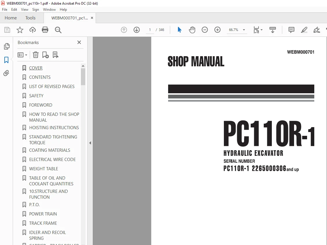
KOMATSU PC110R-1 HYDRAULIC EXCAVATOR Shop Manual WEBM000701 – PDF DOWNLOAD
$29.95
KOMATSU PC110R-1 HYDRAULIC EXCAVATOR Shop Manual WEBM000701 – PDF DOWNLOAD
SERIAL NUMBER
PC11 OR-1 2285000308and up
Description
KOMATSU PC110R-1 HYDRAULIC EXCAVATOR Shop Manual WEBM000701 – PDF DOWNLOAD
FILE DETAILS:
KOMATSU PC110R-1 HYDRAULIC EXCAVATOR Shop Manual WEBM000701 – PDF DOWNLOAD
Language : English
Pages :346
Downloadable : Yes
File Type : PDF
DESCRIPTION:
KOMATSU PC110R-1 HYDRAULIC EXCAVATOR Shop Manual WEBM000701 – PDF DOWNLOAD
SERIAL NUMBER
PC11 OR-1 2285000308and up
GENERAL PRECAUTIONS
A SAFETY
Mistakes in operation extremely dangerous. Read all the Operation and Maintenance Manual care- fully BEFORE operating the machine.
1. Before carrying out any greasing or repairs, read all the precautions written on the decals which are suck on the machine.
2. When carrying out any operation, always wear safety shoes and helmet. Do not wear loose work clothes, or clothes with buttons missing.
• Always wear safety glasses when hitting parts with a hammer.
• Always wear safety glasses when grinding parts with a grinder, etc.
3. If welding repairs are needed, always have a trained, experienced welder carry out the work. When carrying out welding work, always wear welding gloves, apron, glasses, cap and other clothes suited for welding work.
4. When carrying out any operation with two or more workers, always agree on the operating procedure before starting. Always inform your fellow workers before starting any step of the operation. Before starting work, hang UNDER REPAIR signs on the controls in the operator’s compartment.
5. Keep all tools in good condition and leam the cor- rect way to use them.
6. Decide a place in the repair workshop to keep tools and removed parts. Always keep the tools and parts in their correct places. Always keep the work area clean and make sure that there is no dirt or oil on the floor.
Smoke only in the areas provided for smoking. Never smoke while working.
PREPARATIONS FOR WORK
7. Before adding or making any repairs, park the ma- chine on hard, level ground, and block the tracks to prevent the machine from moving.
8. Before starting work, lower blade, bucket or any other work equipment to the ground. If this is not possible, use blocks to prevent the work equipment from falling down. In addition, be sure to lock all the control levers and hang warning sign on them.
9. When disassembling or assembling, support the machine with blocks, jacks or stands before start- ing work.
10. Remove all mud and oil from the steps or other places used to get on and off the machine. Always use the handrails, ladders or steps when getting on or off the machine.
Never jump on or off the machine.
If it is impossible to use the handrails, ladders or steps, use a stand to provide safe footing.
PRECAUTIONS DURING WORK
11. When removing the oil filler cap, drain plug or hy- draulic pressure measuring plugs, loosen them slowly to prevent the oil from spurting out. Before disconnecting or removing components of the hydraulic circuit and engine cooling circuit, first remove the pressure completely from the cir- cuit.
12. The water and oil in the circuits are not hot when the engine in stopped, so be careful not to get bumed.
Wait for the oil water to cool before carrying out any work on the cooling water circuits.
TABLE OF CONTENTS:
KOMATSU PC110R-1 HYDRAULIC EXCAVATOR Shop Manual WEBM000701 – PDF DOWNLOAD
SERIAL NUMBER
PC11 OR-1 2285000308and up
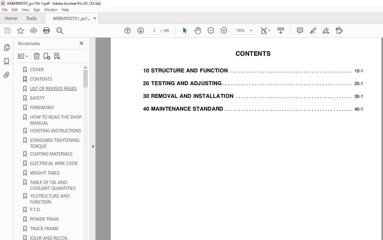
COVER 1
CONTENTS 3
LIST OF REVISED PAGES 5
SAFETY 7
FOREWORD 9
HOW TO READ THE SHOP MANUAL 10
HOISTING INSTRUCTIONS 11
STANDARD TIGHTENING TORQUE 12
COATING MATERIALS 14
ELECTRICAL WIRE CODE 15
WEIGHT TABLE 16
TABLE OF OIL AND COOLANT QUANTITIES 17
10STRUCTURE AND FUNCTION 21
PTO 22
POWER TRAIN 23
TRACK FRAME 25
IDLER AND RECOIL SPRING 26
CARRIER – TRACK ROLLER 27
TRACK SHOE 28
SWING CIRCLE 29
SWING MACHINERY 30
FINAL DRIVE 32
HYDRAULIC DIAGRAM STANDARD 33
HYDRAULIC DIAGRAM WITH 2-PIECE BOOM 35
HYDRAULIC PUMP 36
MAIN PUMP HPV95 37
LS – PC VALVE 42
FIXED THROTTLE VALVE 43
LS VALVE 46
PC VALVE 54
9-SPOOL CONTROL VALVE (STANDARD) 62
10-SPOOL CONTROL VALVE (STANDARD + 2-PIECE BOOM) 64
SWING MOTOR 92
SWING MOTOR RELIEF VALVE 93
SWIVEL JOINT 94
TRAVEL MOTOR 96
CYLINDERS 98
SERVOCONTROL FEED UNIT100
ACCUMULATOR105
PPC VALVES ATTACHMENT106
PPC VALVES (BLADE, BOOM SWING, 2-PIECE BOOM)110
TRAVEL PPC VALVE114
BOOM AND ARM SAFETY VALVE119
BLADE SAFETY VALVE120
2-PIECE BOOM SAFETY VALVE121
OVERLOAD SENSOR SWITCH122
SOLENOID VALVE GROUP ST1123
SOLENOID VALVE GROUP OP1 (Y3-Y4)124
ELECTRICAL CIRCUIT DIAGRAM (1/3)125
ELECTRICAL CIRCUIT DIAGRAM (2/3)127
ELECTRICAL CIRCUIT DIAGRAM (3/3)129
20TESTING AND ADJUSTMENTS133
NORMAL OR STANDARD TECHNICAL DATA134
SPECIAL TOOLS149
MEASURING THE ENGINE SPEED150
ADJUSTING VALVE CLEARANCE151
MEASURING COMPRESSION PRESSURE152
TESTING AND ADJUSTING FUEL INJECTION TIMING153
TESTING AND ADJUSTING FAN BELT TENSION155
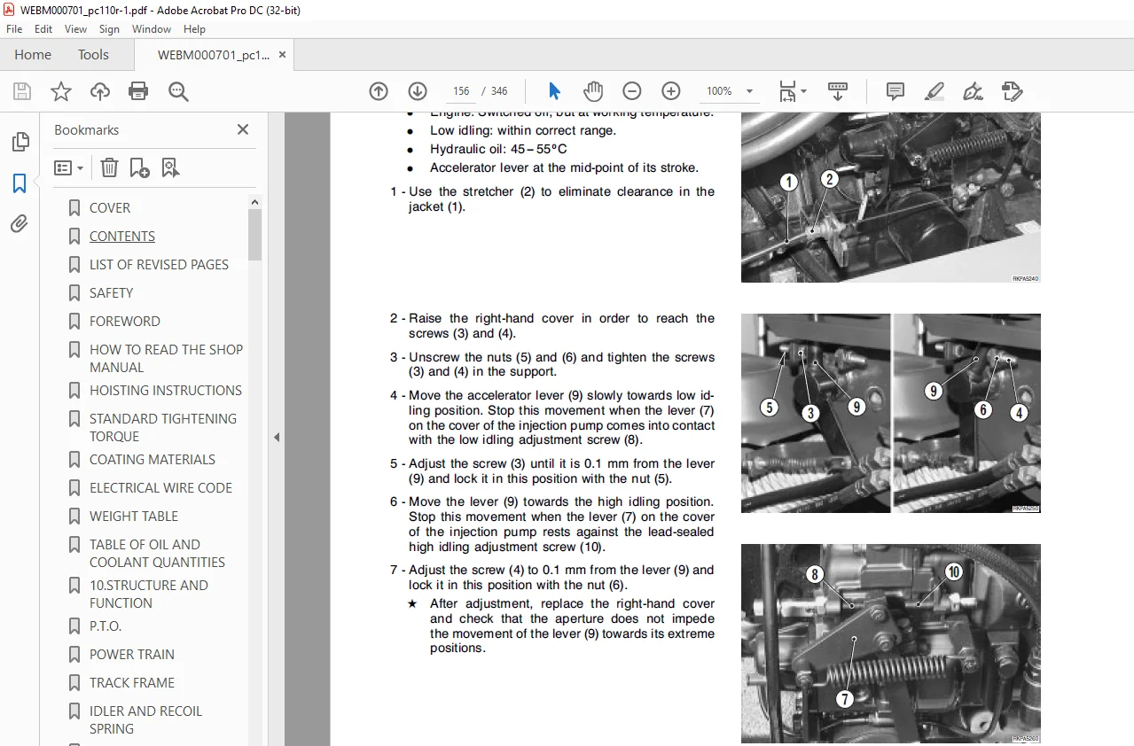
ADJUSTING THE STROKE OF THE ACCELERATOR LEVER156
ADJUSTING PPC VALVES CLEARANCE157
ADJUSTING THE SAFETY MICROSWITCH158
MEASURING THE SWING CIRCLE AXIAL CLEARANCE159
TESTING AND ADJUSTING TRACK-SHOE TENSION160
AIR BLEEDING FROM HYDRAULIC CIRCUITS161
RELEASING RESIDUAL PRESSURE FROM THE CIRCUITS164
CHECKING AND REGULATING PRESSURE IN THE HYDRAULIC CIRCUITS165
TESTING AND SETTING OF MAIN VALVES166
ADJUSTING PC VALVE168
MEASURING LS DIFFERENTIAL PRESSURE AND ADJUSTING LS VALVE169
CHECKING AND ADJUSTING PRESSURES IN THE SERVOCONTROL FEED UNIT171
MEASURING PUMPS DELIVERY AND FLOW CONTROL STARTING POINT PUMP P1172
MEASURING TRAVEL DEVIATION174
ADJUSTING THE MAXIMUM SPEED OF THE TRAVEL MOTORS175
MEASURING INNER OIL LEAKAGE OF TRAVEL MOTOR176
ADJUSTING BOOM AND ARM SAFETY VALVES177
ADJUSTING 2nd BOOM SAFETY VALVES178
MEASURING AND SETTING OF PRESSURE SWITCH SIGNAL OVERLOAD OPERATION179
MEASUREMENT OF INTERNAL OIL LEAKAGES IN THE SWING MOTOR180
CHECKING FOR LEAKAGES INSIDE THE SWIVEL JOINT181
ANALYSIS OF THE CAUSES OF HYDRAULIC DRIFTS183
30DISASSEMBLY AND ASSEMBLY193
HOW TO READ THE MANUAL195
PRECAUTIONS TO BE TAKEN WHEN WORKING196
SPECIAL TOOLS197
STARTER MOTOR199
ALTERNATOR200
INJECTION PUMP201
INJECTION NOZZLE205
THERMOSTAT206
EXHAUST PIPE-MUFFLER207
TURBOCOMPRESSOR208
CYLINDER HEAD209
SEAT214
CABIN215
ENGINE HOOD216
FRONT HOOD217
HEATING FAN218
RADIATOR219
FUEL TANK221
HYDRAULIC OIL TANK223
ENGINE-PUMP GROUP224
PUMP GROUP228
ENGINE-PUMP COUPLING JOINT230
GEAR-PUMP231
SWIVEL JOINT232
SWING MOTOR233
SWING MACHINERY234
CONTROL VALVE253
REVOLVING FRAME254
COUNTERWEIGHT256
SWING CIRCLE257
TRACK SHOES258
SPROCKET ASSEMBLY259
FINAL DRIVE260
IDLER AND RECOIL SPRING ASSEMBLY261
RECOIL SPRING ASSEMBLY262
IDLER ASSEMBLY264
TRACK ROLLER267
CARRIER ROLLER268
RH PPC VALVE (BOOM – BUCKET)269
LH PPC VALVE (ARM – SWING)271
BLADE PPC VALVE273
TRAVEL PEDAL CONTROL274
1st BOOM SWING PEDAL CONTROL275
BOOM CYLINDER (FOR 1-PIECE BOOM)276
BOOM CYLINDER (FOR 2-PIECE BOOM)277
2nd BOOM CYLINDERS279
ARM CYLINDER281
BUCKET CYLINDER282
BOOM SWING CYLINDER283
BLADE CYLINDER284
WORK EQUIPMENT CYLINDERS285
WORK EQUIPMENT (FOR 1-PIECE BOOM)290
WORK EQUIPMENT (FOR 2-PIECE BOOM)291
BUCKET293
ARM294
2nd BOOM297
BOOM (FOR 1-PIECE BOOM)299
BOOM (FOR 2-PIECE BOOM)300
SWING BRACKET302
BLADE303
40MAINTENANCE STANDARD307
PTO308
SWING CIRCLE309
TRACK FRAME310
IDLER311
CARRIER ROLLER312
TRACK ROLLER313
TRACK SHOE314
SPROCKET315
SWING MACHINERY316
FINAL DRIVE318
HYDRAULIC PUMP319
CONTROL VALVE320
SWING MOTOR330
SWIVEL JOINT331
TRAVEL MOTOR332
SERVOCONTROL FEED UNIT334
TRAVEL PPC VALVE335
PPC VALVES336
SAFETY VALVE338
CYLINDERS340
WORK EQUIPMENT (1-PIECE BOOM)342
WORK EQUIPMENT (2-PIECE BOOM)344
IMAGES PREVIEW OF THE MANUAL:
S.M 18/12/24



