
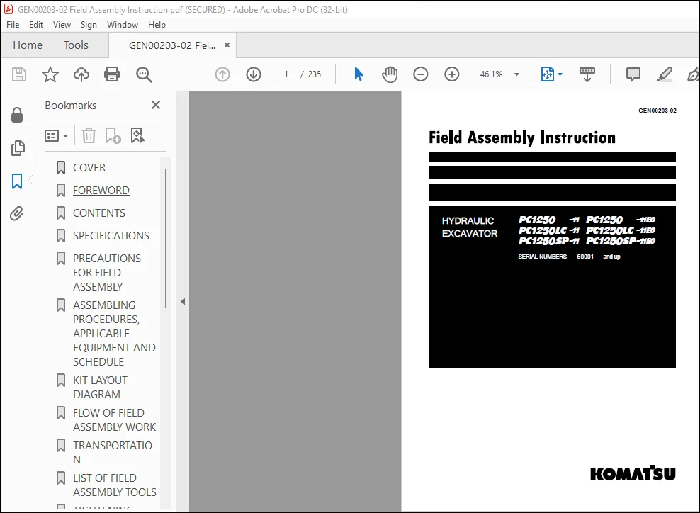
Komatsu PC1250-11 PC1250-11E0 PC1250LC-11 PC1250LC-11E0PC 1250SP-11 PC1250SP-11E0 Hydraulic Excavator Field Assembly Instruction Manual GEN00203-02 – PDF DOWNLOAD
Original price was: $86.95.$28.95Current price is: $28.95.
Komatsu PC1250-11 PC1250-11E0 PC1250LC-11 PC1250LC-11E0PC 1250SP-11 PC1250SP-11E0 Hydraulic Excavator Field Assembly Instruction Manual GEN00203-02 – PDF DOWNLOAD
Description
Komatsu PC1250-11 PC1250-11E0 PC1250LC-11 PC1250LC-11E0PC 1250SP-11 PC1250SP-11E0 Hydraulic Excavator Field Assembly Instruction Manual GEN00203-02 – PDF DOWNLOAD
FILE DETAILS:
Komatsu PC1250-11 PC1250-11E0 PC1250LC-11 PC1250LC-11E0PC 1250SP-11 PC1250SP-11E0 Hydraulic Excavator Field Assembly Instruction Manual GEN00203-02 – PDF DOWNLOAD
Language : English
Pages : 235
Downloadable : Yes
File Type : PDF
Size: 33.7 MB
IMAGES PREVIEW OF THE MANUAL:
DESCRIPTION:
Komatsu PC1250-11 PC1250-11E0 PC1250LC-11 PC1250LC-11E0PC 1250SP-11 PC1250SP-11E0 Hydraulic Excavator Field Assembly Instruction Manual GEN00203-02 – PDF DOWNLOAD
SERIAL NUMBERS 50001 and up
- The Komatsu PC1250-11 PC1250-11E0 PC1250LC-11 PC1250LC-11E0 PC1250SP-11 PC1250SP-11E0 Hydraulic Excavator Field Assembly Instruction Manual (GEN00203-02) is a comprehensive resource for anyone who is involved in the field assembly of Komatsu PC1250-11, PC1250-11E0, PC1250LC-11, PC1250LC-11E0, PC1250SP-11, or PC1250SP-11E0 hydraulic excavators. This manual provides detailed and step-by-step instructions for the field assembly process, including illustrations and diagrams to help users understand the procedures.
- The field assembly manual covers all the key aspects of the assembly process, from unloading the excavator from the transport vehicle to final assembly and testing. The manual includes information on the tools and equipment needed for the assembly process, as well as important safety precautions and guidelines to follow. This information is crucial for ensuring that the assembly process is performed safely and correctly.
- The manual also includes detailed information on the hydraulic, electrical, and mechanical systems of the hydraulic excavator, including the hydraulic pump, hydraulic cylinder, hydraulic valves, electrical wiring, and more. This information can help users understand the different components and systems of the hydraulic excavator, and can help ensure that they are assembled correctly.
- In addition to providing important information on the field assembly process, the Komatsu PC1250-11 PC1250-11E0 PC1250LC-11 PC1250LC-11E0 PC1250SP-11 PC1250SP-11E0 Hydraulic Excavator Field Assembly Instruction Manual also includes important information on the maintenance and operation of the hydraulic excavator. This information can help users keep their hydraulic excavator in good working condition and can help avoid costly repairs.
- The Komatsu PC1250-11 PC1250-11E0 PC1250LC-11 PC1250LC-11E0 PC1250SP-11 PC1250SP-11E0 Hydraulic Excavator Field Assembly Instruction Manual is a valuable resource for anyone who is involved in the field assembly of Komatsu PC1250-11, PC1250-11E0, PC1250LC-11, PC1250LC-11E0, PC1250SP-11, or PC1250SP-11E0 hydraulic excavators. The manual provides a wealth of information that can help ensure that the assembly process is performed correctly and safely, and can help ensure that the hydraulic excavator is ready to perform at its best.
TABLE OF CONTENTS:
Komatsu PC1250-11 PC1250-11E0 PC1250LC-11 PC1250LC-11E0PC 1250SP-11 PC1250SP-11E0 Hydraulic Excavator Field Assembly Instruction Manual GEN00203-02 – PDF DOWNLOAD
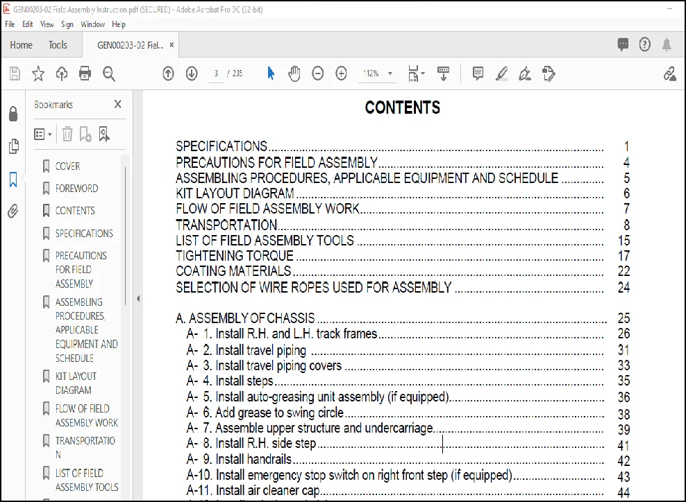
SPECIFICATIONS……………………………………………………………………………………………….. 1
PRECAUTIONS FOR FIELD ASSEMBLY……………………………………………………………….. 4
ASSEMBLING PROCEDURES, APPLICABLE EQUIPMENT AND SCHEDULE ………….. 5
KIT LAYOUT DIAGRAM ……………………………………………………………………………………….. 6
FLOW OF FIELD ASSEMBLY WORK…………………………………………………………………….. 7
TRANSPORTATION…………………………………………………………………………………………….. 8
LIST OF FIELD ASSEMBLY TOOLS ……………………………………………………………………… 15
TIGHTENING TORQUE ……………………………………………………………………………………….. 17
COATING MATERIALS ………………………………………………………………………………………… 22
SELECTION OF WIRE ROPES USED FOR ASSEMBLY …………………………………………. 24
A. ASSEMBLY OF CHASSIS ………………………………………………………………………………….. 25
A- 1. Install R.H. and L.H. track frames……………………………………………………………….. 26
A- 2. Install travel piping …………………………………………………………………………………… 31
A- 3. Install travel piping covers …………………………………………………………………………. 33
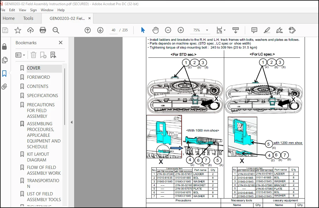
A- 4. Install steps……………………………………………………………………………………………… 35
A- 6. Add grease to swing circle………………………………………………………………………….
A- 7. Assemble upper structure and undercarriage………………………………………………..
38
A- 8. Install R.H. side step………………………………………………………………………………….
39
A- 9. Install handrails…………………………………………………………………………………………
41
A-10. Install emergency stop switch on right front step (if equipped)…………………………
42
A-11. Install air cleaner cap…………………………………………………………………………………
43
A-12. Install swivel travel piping …………………………………………………………………………..
44
A-18. Install KomVision camera …………………………………………………………………………..
61
A-19. Install counterweight………………………………………………………………………………….
62
A-20. Install counterweight revolving warning lamp (if equipped) ……………………………..
70
A-21. Install counterweight rear lamp (if equipped)…………………………………………………
71
A-13. Install L.H. side step ………………………………………………………………………………….
45
A-14. Install fixed ladder……………………………………………………………………………………..
46
A-15. Install hydraulic stairway (if equipped)………………………………………………………….
52
A-16. Install flash light (if equipped) ……………………………………………………………………..
54
A-17. Install L.H. side step emergency stop switch (if equipped)………………………………
59
A-22. Install radiator cover ………………………………………………………………………………….
73
A-23. Install exhaust tail pipe………………………………………………………………………………..
75
A-24. Change installed position of step light ………………………………………………………….
76
A-25. Change installed position of wireless LAN antenna ……………………………………….
78
A-26. Install operator’s cab revolving warning lamp (if equipped)……………………………..
79
A-27. Install operator’s cab handrail……………………………………………………………………..
80
A-28. Install L.H. rearview mirror………………………………………………………………………….
82
A-29. Install R.H. rearview mirror …………………………………………………………………………
84
A-30. Prepare for bleeding air from travel motor…………………………………………………….
86
A-31. Bleed air from hydraulic pump section …………………………………………………………
89
A-32. Tighten swing circle mounting bolts to specified torque ………………………………….
90
A-33. Check and adjust track tension …………………………………………………………………..
91
A-34. Check fuel, coolant and oil levels ………………………………………………………………..
92
A-35. Parts to be touched up after field assembly ………………………………………………….
95
A- 5. Install auto-greasing unit assembly (if equipped)…………………………………………… 36
98
B. ASSEMBLING OF WORK EQUIPMENT OF BACKHOE ………………………………………. 99
B- 1. Release remaining pressure in hydraulic circuit……………………………………………… 100
B- 2. Install arm cylinder to boom…………………………………………………………………………. 102
B- 3. Install arm cylinder hose……………………………………………………………………………… 103
B- 4. Install boom cylinder to revolving frame………………………………………………………… 104
B- 5. Install boom cylinder hose…………………………………………………………………………… 105
B- 6. Bleed air from cylinder ……………………………………………………………………………….. 106
B- 7. Install boom foot dust seal ………………………………………………………………………….. 107
B- 8. Install boom assembly………………………………………………………………………………… 108
B- 9. Install boom cylinder to boom assembly ……………………………………………………….. 109
B-10. Install boom connection hoses (between chassis and boom assembly)…………….. 110
B-11. Install arm assembly ………………………………………………………………………………….. 111
B-12. Install bucket cylinder hoses (between boom and bucket cylinder) ………………….. 113
B-13. Install bucket assembly ……………………………………………………………………………… 114
B-14. Clearance standard for installation of work equipment …………………………………… 117
B-15. Install work equipment grease piping…………………………………………………………… 118
B-16. Install work equipment lamps……………………………………………………………………… 119
B-17. Grease after assembling work equipment…………………………………………………….. 120
B-18. Bleed air from swing motor ………………………………………………………………………… 121
B-19. Bleed air from travel motor…………………………………………………………………………. 122
B-20. Install travel motor guard……………………………………………………………………………. 123
B-21. Bleed air from hydraulic stairway (if equipped) ……………………………………………… 124
M. PROCEDURE FOR INSPECTION AND MAINTENANCE AFTER COMPLETION
ASSEMBLY …………………………………………………………………………………………………….. 125
M- 1. Replace return filter (Replace standard filter → flushing filter) …………………………. 126
M- 2. Flush hydraulic circuit ………………………………………………………………………………… 128
M- 3. Replace return filter (Replace flushing filter → standard filter) ………………………… 130
M- 4. Replace pilot filter ……………………………………………………………………………………… 132
M- 5. Setting of KomVision (Camera calibration)…………………………………………………… 133
M- 7. Method for starting up KOMTRAX terminal and default setting of
KOMTRAX Plus controller…………………………………………………………………………. 147
M- 6. Inspection method of 12m visibility (KomVision)………………………………………… 145
C. PROCEDURE FOR ASSEMBLING OF WORK EQUIPMENT
OF LOADING SHOVEL …………………. 149
Transportation posture (only work equipment) ……………………………………………………….. 150
C- 1. Release remaining pressure in hydraulic circuit ……………………………………………… 151
C- 2. Bleed air from cylinder ………………………………………………………………………………… 153
C- 3. Flush hydraulic circuit …………………………………………………………………………………. 154
C- 4. Installation of Arm Cylinder Bottoms ……………………………………………………………… 155
C- 5. Connection of Boom and Arm ………………………………………………………………………. 156
C- 6. Pulling out Boom Foot Pin and Boom Cylinder Foot Pin ………………………………….. 158
C- 7. Installation of Boom and Arm Assembly ………………………………………………………… 159
C- 8. Installation of Boom Hoses (Between Chassis and Boom) ……………………………….. 160
C- 9. Installation of Hoses Between Boom and Arm (Bottom Dump) ………………………….. 161
C-10. Installation of Boom Cylinder Bottoms ………………………………………………………….. 162
C-11. Installation of Boom Cylinder Hoses …………………………………………………………….. 163
C-12. Installation of Boom Cylinder Head Pin …………………………………………………………. 164
C-13. Installation of Arm Cylinder Hoses ………………………………………………………………… 165
C-14. Installation of Bucket Cylinder ……………………………………………………………………… 166
C-15. Installation of Bucket Cylinder Hoses ……………………………………………………………. 167
C-16. Installation of Bucket Assembly ………………………………………………………………….. 168
C-17. Installation of Bottom Dump Cylinder Hoses …………………………………………………. 170
C-18. Maintenance Standard ………………………………………………………………………………. 171
C-19. Installation of Working Lamp ………………………………………………………………………. 172
C-20. Installation of Work Equipment Greasing Piping ……………………………………………. 173
C-21. Checking Oil Level in Hydraulic Tank and Adding Oil …………………………………….. 174
C-22. Greasing After Assembling Work Equipment ………………………………………………… 175
Inspection of each part after assembly of loader …………………………………………………….. 176
Need help? Contact: [email protected]
https://vimeo.com/798342928
PLEASE NOTE:
- This is the SAME exact manual used by your dealers to fix your vehicle.
- The same can be yours in the next 2-3 mins as you will be directed to the download page immediately after paying for the manual.
- Any queries / doubts regarding your purchase, please feel free to contact [email protected]
S.V



