Komatsu PC1250-7 PC1250LC-7 PC1250SP-7 Hydraulic Excavator Field Assembly Instruction Manual SN 20001 and up – PDF DOWNLOAD
Original price was: $41.95.$14.95Current price is: $14.95.
Komatsu PC1250-7 PC1250LC-7 PC1250SP-7 Hydraulic Excavator Field Assembly Instruction Manual
Book Code: GEN00015-03
SERIAL NUMBERS:
PC1250- 20001 and up
PC1250LC- 20001 and up
PC1250SP- 20001 and up
Description
Komatsu PC1250-7 PC1250LC-7 PC1250SP-7 Hydraulic Excavator Field Assembly Instruction Manual
TABLE OF CONTENTS:
Komatsu PC1250-7 PC1250LC-7 PC1250SP-7 Hydraulic Excavator Field Assembly Instruction Manual
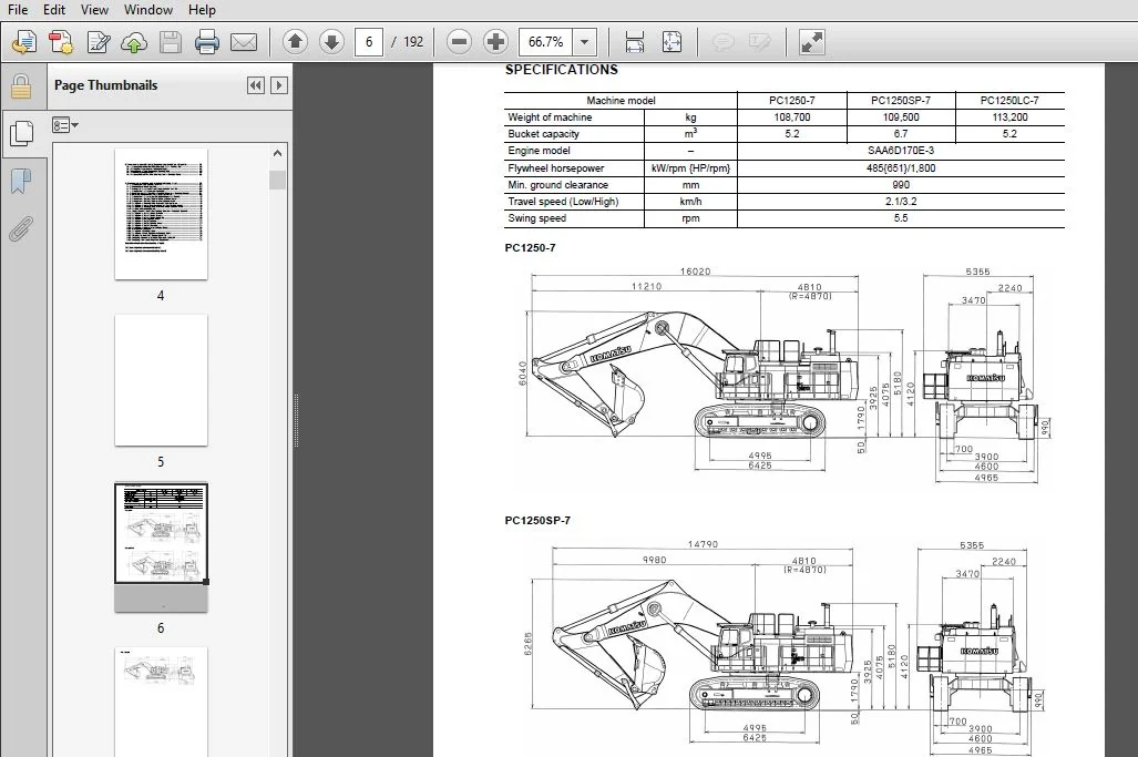
Specifications 1
Precautions for Field Assembly 3
Assembling Procedures, Applicable Equipment and Schedule 4
Kit Layout Diagram 5
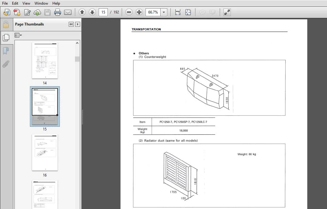
Transportation 6
List of assembling tools to be brought in field 13
Tightening Torque 15
Coating Materials 19
List of parts sent individually 21
A Assembly of Chassis 29
A- 1 Installation of Track Frame 30
A- 2 Supplying Grease to Swing Circle 33
A- 3 Assembly of Upper Structure and Undercarriage 34
A- 4 Installation of Travel Piping 35
A- 5 Installation of Travel Piping Cover 36
A- 6 Installation of Swivel Travel Piping 37
A- 6 Sticking Sheets (Counterweight) 38
A- 7 Installation of Counterweight 40
A- 8 Installation of Steps 41
A- 9 Installation of Left Side Step (With Handrail) 42
A-10 Installation of Right Side Step 44
A-11 Installation of Handrail 45
A-12 Installation of Radiator Cover 46
A-13 Installation of Intake Air Cap and Muffler Tail Pipe 51
A-14 Installation of Left Rear-view Mirror 52
A-15 Installation of Right Rear-view Mirror 53
A-16 Preparation for Bleeding Air from Travel Motor 54
A-17 Procedure for Bleeding Air from Hydraulic Circuit 55
A-18 Tightening Swing Circle Mounting Bolts Permanently 56
A-19 Testing and Adjusting Track Link 57
A-20 Inspection of Oil Amount and Water Amount 60
A-21 Parts To Be Touched Up After Field Assembly 62
B Assembling of work equipment of backhoe 63
B- 1 Boom Foot Pin, Boom Cylinder Foot Pin 64
B- 2 Installation of Boom Cylinder Foot 65
B- 3 Installation of Boom Cylinder Hoses 66
B- 4 Installation of Boom Assembly 67
B- 5 Installation of Boom Cylinder 68
B- 6 Installation of Boom Hoses (Between Chassis and Boom) 69
B- 7 Installation of Arm Cylinder 70
B- 8 Installation of Arm Cylinder Hoses 71
B- 9 Installation of Arm Assembly 72
B-10 Installation of Bucket Cylinder Hoses (Between Boom and Bucket Cylinder) 74
B-11 Installation of Bucket Assembly 75
B-12 Clearance Standards for Work Equipment Mount 77
B-13 Installation of Work Equipment Grease Piping 78
B-14 Procedure for Bleeding Air from Travel Motor 79
B-15 Bleeding Air from Swing Motor 81
B-16 Bleeding Air from Cylinder 82
B-17 Installation of Work Equipment Electric Wiring 83
B-18 Installation of Floor Mat 84
B-19 Greasing Assembled Work Equipment 85
M Procedure for inspection and maintenance after completion of assembly 87
M- 1 Reassembly of Return Filter (Standard Part o Flushing Part) 88
M- 2 Releasing Pressure from Hydraulic Circuit 91
M- 3 Installation of Work Equipment Flushing Tube 92
M- 4 Flushing Hydraulic Circuit 94
M- 5 Reassembly of Pilot Filter (Flushing Part o Standard Part) 95
C Procedure for assembling work equipment of loading shovel 97
C- 1 Installation of Arm Cylinder Bottoms 102
C- 2 Connection of Boom and Arm 103
C- 3 Pulling out Boom Foot Pin and Boom Cylinder Foot Pin 105
C- 4 Installation of Boom and Arm Assembly 106
C- 5 Replacement of Return Filter (Standard Element o Flushing Element) 107
C- 6 Releasing Residual Pressure in Hydraulic Circuit 109
C- 7 Installation of Boom Hoses (Between Chassis and Boom) 110
C- 8 Installation of Flushing Tube for Boom Cylinder Hoses 111
C- 9 Installation of Flushing Tube for Arm Cylinder Hoses 112
C-10 Installation of Flushing Tube for Bucket Cylinder Hoses 113
C-11 Installation of Hoses Between Boom and Arm (Bottom Dump) 114
C-12 Installation of Flushing Tube for Bottom Dump Cylinder Hoses 115
C-13 Flushing of Hydraulic Circuit 116
C-14 Replacement of Pilot Filter (Flushing Element o Standard Element) 117
C-15 Installation of Boom Cylinder Bottoms 118
C-16 Installation of Boom Cylinder Hoses 119
C-17 Installation of Boom Cylinder Head Pin 120
C-18 Installation of Arm Cylinder Hoses 121
C-19 Installation of Bucket Cylinder 122
C-20 Installation of Bucket Cylinder Hoses 123
C-21 Installation of Bucket Assembly 124
C-22 Installation of Bottom Dump Cylinder Hoses 126
C-23 Maintenance Standard 127
C-24 Installation of Working Lamp 128
C-25 Installation of Work Equipment Greasing Piping 129
C-26 Bleeding Air from Work Equipment Circuit 130
C-27 Checking Oil Level in Hydraulic Tank and Adding Oil 131
C-28 Greasing After Assembling Work Equipment 132
Inspection of each part after assembly of loader
Field assembly inspection report (Backhoe)
Field assembly inspection report (Loading shovel)
KOMATSU PC1250-7 PC1250LC-7 PC1250SP-7 HYDRAULIC EXCAVATOR FIELD ASSEMBLY INSTRUCTION MANUAL SN 20001 AND UP – PDF DOWNLOAD:
IMAGES PREVIEW OF THE MANUAL:
DESCRIPTION:
Komatsu PC1250-7 PC1250LC-7 PC1250SP-7 Hydraulic Excavator Field Assembly Instruction Manual
FOREWORD:
- Since this machine is large in size, it is divided into some units to meet the transportation conditions and regulations applied to the transportation route when shipped from our factory. This manual describes how to assemble the units into the complete machine in the field.
- We hope that this machine will display its quality and you will use it safely according to the operation manual. Many units are large in size and heavy in weight and may be handled in a dangerous place or posture and many workers may have to work together to sling them with cranes.
- Accordingly, before starting the assembly work, the work supervisor is required to hold a safety meeting to oblige the workers to put on protective gear and appoint a work leader and a crane work signal man and allot roles to all the workers for safe work.
- In particular, the above meeting is more important when worker of different languages and customs work together. The following is a reference supervision system diagram. When the work equipment is installed, the engine must be operated.
- Accordingly, before installing the work equipment, inspect and maintain the machine thoroughly. Note that this manual does not describe the whole specification of the machine but describes only the basic specification. If you have any question when dividing and transporting the machine by yourself in future, ask one of our distributors.
PLEASE NOTE:
- This is not a physical manual but a digital manual – meaning no physical copy will be couriered to you. The manual can be yours in the next 2 mins as once you make the payment, you will be directed to the download page IMMEDIATELY.
- This is the same manual used by the dealers inorder to diagnose your vehicle of its faults.
- Require some other service manual or have any queries: please WRITE to us at [email protected]


