
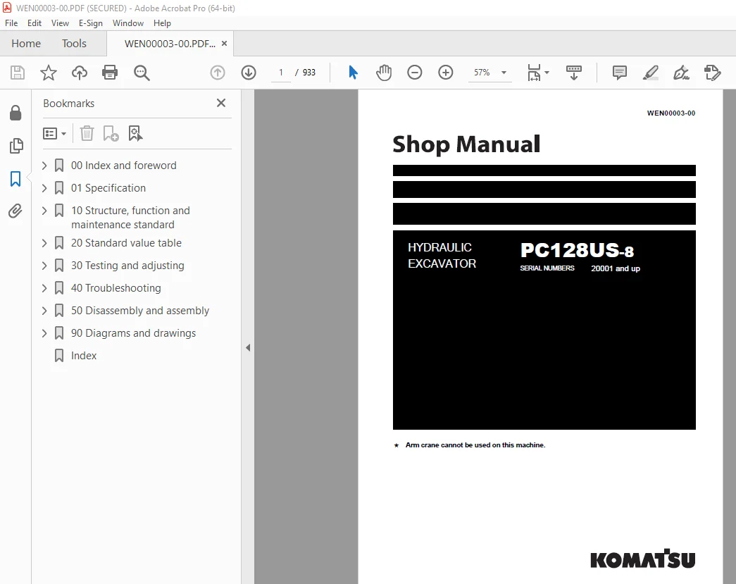
Komatsu PC128US-8 Hydraulic Excavator Shop Manual WEN00003 PDF
$34.95
Komatsu PC128US-8 Hydraulic Excavator Shop Manual WEN00003 – PDF DOWNLOAD
SERIAL NUMBERS 20001 and up
Description
Komatsu PC128US-8 Hydraulic Excavator Shop Manual WEN00003 – PDF DOWNLOAD
FILE DETAILS:
Komatsu PC128US-8 Hydraulic Excavator Shop Manual WEN00003 – PDF DOWNLOAD
Language : English
Pages : 933
Downloadable : Yes
File Type : PDF
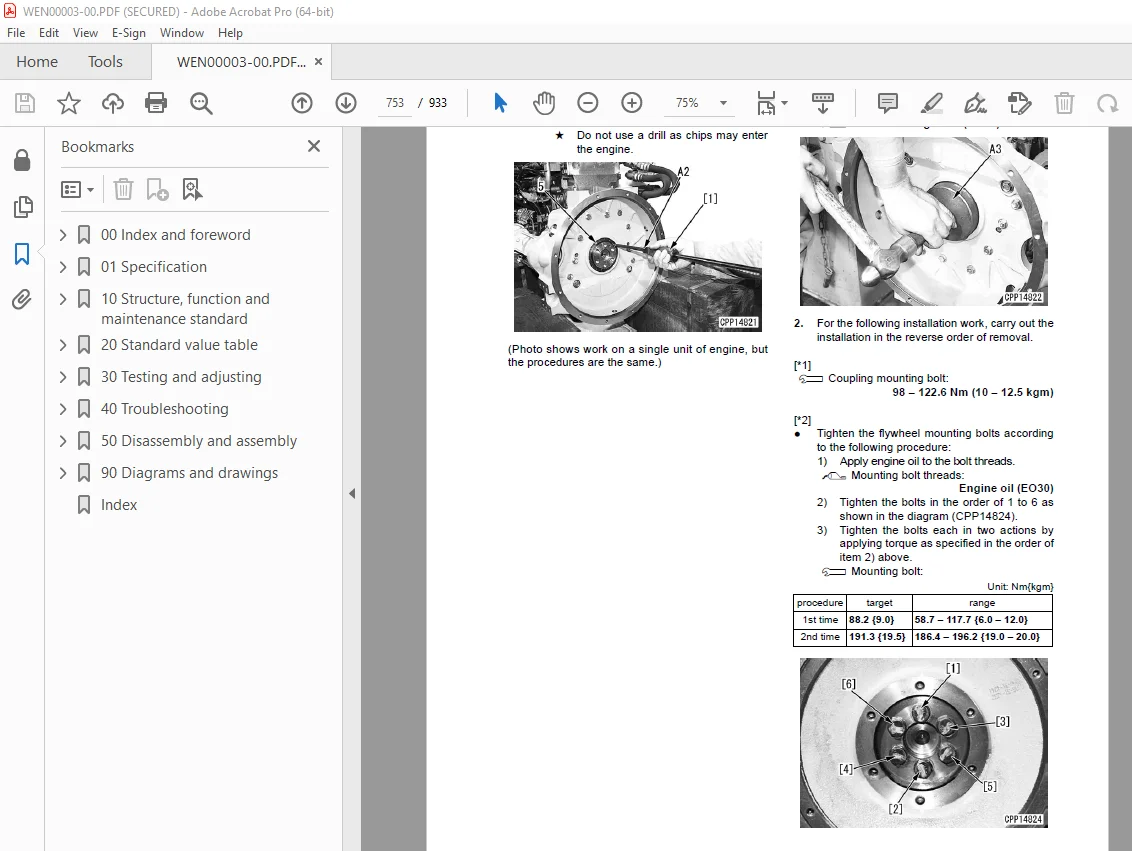
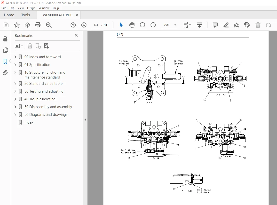
IMAGES PREVIEW OF THE MANUAL:
DESCRIPTION:
Komatsu PC128US-8 Hydraulic Excavator Shop Manual WEN00003 – PDF DOWNLOAD
SERIAL NUMBERS 20001 and up
How to read the shop manual :
1. Composition of shop manual:
This shop manual contains the necessary technical information for services performed in a workshop.
For ease of understanding, the manual is divided into the following sections.
00. Index and foreword
This section explains the shop manuals list, table of contents, safety, and basic information.
01. Specification
This section explains the specifications of the machine.
10. Structure, function and maintenance standard
This section explains the structure, function, and maintenance standard values of each component.
The structure and function sub-section explains the structure and function of each component. It
serves not only to give an understanding of the structure, but also serves as reference material for
troubleshooting. The maintenance standard sub-section explains the criteria and remedies for disassembly
and service.
20. Standard value table
This section explains the standard values for new machine and judgement criteria for testing,
adjusting, and troubleshooting. This standard value table is used to check the standard values in
testing and adjusting and to judge parts in troubleshooting.
30. Testing and adjusting
This section explains measuring instruments and measuring methods for testing and adjusting, and
method of adjusting each part. The standard values and judgement criteria for testing and adjusting
are explained in Testing and adjusting.
40. Troubleshooting
This section explains how to find out failed parts and how to repair them. The troubleshooting is
divided by failure modes. The “S mode” of the troubleshooting related to the engine may be also
explained in the Chassis volume and Engine volume. In this case, see the Chassis volume.
50. Disassembly and assembly
This section explains the special tools and procedures for removing, installing, disassembling, and
assembling each component, as well as precautions for them. In addition, tightening torque and
quantity and weight of coating material, oil, grease, and coolant necessary for the work are also
explained.
90. Diagrams and drawings (chassis volume)/Repair and replacement of parts (engine volume)
q Chassis volume
This section gives hydraulic circuit diagrams and electrical circuit diagrams.
q Engine volume
This section explains the method of reproducing, repairing, and replacing parts.
TABLE OF CONTENTS:
Komatsu PC128US-8 Hydraulic Excavator Shop Manual WEN00003 – PDF DOWNLOAD
SERIAL NUMBERS 20001 and up
00 Index and foreword 3
Index 4
Table of contents 4
Foreword and general information 11
Safety notice 11
How to read the shop manual 16
Explanation of terms for maintenance standard 18
Handling of electric equipment and hydraulic component 20
Handling of connectors newly used for engines 29
How to read electric wire code 32
Precautions when carrying out operation 35
Method of disassembling and connecting push-pull type coupler 38
Standard tightening torque table 41
Conversion table 45
01 Specification 51
Specification and technical data 53
Specification dimension drawing 53
Working range diagram 54
Specifications 55
Weight table 58
Table of fuel, coolant and lubricants 60
10 Structure, function and maintenance standard 63
Engine and cooling system 66
Engine mount 66
PTO 67
Cooling system 68
Power train 70
Power train 70
Swing circle 71
Swing machinery 72
Undercarriage and frame 74
Track frame 74
Idler cushion 75
Idler 76
Track roller 77
Carrier roller 78
Sprocket 79
Track shoe 80
Hydraulic system 86
Hydraulic equipment layout drawing 86
Valve control 88
Hydraulic tank and filter 90
Hydraulic pump 92
Control valve 118
CLSS 130
Functions and operation by valve 134
PPC valve 164
Swing motor 181
Travel motor 189
Center swivel joint 198
Solenoid valve 202
PPC accumulator 206
Holding valve 208
Work equipment 214
Work equipment 214
Dimensions of components 216
Hydraulic cylinder 220
Cab and its attachments 222
Air conditioner 222
Electrical system 234
Electronic control system 234
Monitor system 267
KOMTRAX system 281
Sensor 283
20 Standard value table 289
Standard service value table 291
Standard value table for engine related parts 291
Standard value table for chassis related parts 292
30 Testing and adjusting 301
Related information on testing and adjusting 303
Tools for testing, adjusting, and troubleshooting 303
Sketches of special tools 307
Engine and cooling system 308
Testing engine speed 308
Testing exhaust temperature 309
Checking exhaust gas color 310
Adjusting valve clearance 311
Testing compression pressure 313
Testing blow-by pressure 315
Testing engine oil pressure 316
Handling fuel system parts 317
Releasing residual pressure from fuel system 317
Testing fuel pressure 318
Testing fuel return rate and fuel leakage 319
Bleeding air from fuel circuit 321
Checking fuel circuit for leakage 323
Testing and adjusting alternator belt tension 324
Checking and adjusting air conditioner compressor belt tension 325
Power train 326
Testing swing circle bearing clearance 326
Undercarriage and frame 327
Checking and adjusting track shoe tension 327
Hydraulic system 329
Testing and adjusting oil pressure in work equipment, swing, and travel circuits 329
Testing control circuit basic pressure 332
Testing and adjusting oil pressure in pump PC control circuit 333
Testing and adjusting oil pressure in pump LS control circuit 336
Testing solenoid valve output pressure 340
Testing PPC valve output pressure 341
Adjusting play of work equipment and swing PPC valves 343
Checking parts which cause hydraulic drift of work equipment 344
Testing and adjusting travel deviation 346
Releasing residual pressure from hydraulic circuit 348
Testing oil leakage 349
Bleeding air from each part 352
Cab and its attachments 354
Checking cab tipping stopper 354
Adjusting mirrors 354
Electrical system 356
Special functions of machine monitor 356
Handling voltage circuit of engine controller 408
Preparation work for troubleshooting of electrical system 409
Procedure for testing diodes 414
Pm-Clinic 415
Pm Clinic service 415
40 Troubleshooting 419
Related information on troubleshooting 424
Points to remember when performing troubleshooting 424
How to proceed in troubleshooting 426
Checks before troubleshooting 428
Classification and procedures for troubleshooting 429
Information in troubleshooting table 430
Phenomena looking like troubles and troubleshooting Nos 432
Connection table of connector by No of pins 435
T-box and T-adapter list 472
Failure code table 476
Fuse locations 480
Troubleshooting by failure code 482
Failure code [989L00] Engine controller lock caution 1 482
Failure code [989M00] Engine controller lock caution 2 482
Failure code [989N00] Engine controller lock caution 3 483
Failure code [AB00KE] Charge voltage low 484
Failure code [B@BAZG] Eng oil press low 486
Failure code [B@BAZK] Eng oil level low 486
Failure code [B@BCNS] Eng coolant overheat 487
Failure code [B@HANS] Hydr oil overheat 487
Failure code [CA111] ECM critical internal failure 488
Failure code [CA115] Eng Ne and Bkup speed sensor error 491
Failure code [CA122] Charge air press sensor high error 492
Failure code [CA123] Charge air press sensor low error 494
Failure code [CA131] Throttle sensor high error 496
Failure code [CA132] Throttle sensor low error 498
Failure code [CA144] Coolant temp sensor high error 499
Failure code [CA145] Coolant temp sensor low error 500
Failure code [CA153] Charge air temp sensor high error 501
Failure code [CA154] Charge air temp sensor low error 502
Failure code [CA187] Sensor sup 2 volt low error 503
Failure code [CA221] Ambient air press sensor high error 504
Failure code [CA222] Ambient air press sensor low error 506
Failure code [CA227] Sensor sup 2 volt high error 508
Failure code [CA234] Eng overspeed 509
Failure code [CA238] Ne speed sensor sup volt error 510
Failure code [CA271] IMV/PCV1 short error 512
Failure code [CA272] IMV/PCV1 open error 513
Failure code [CA322] Injector #1 (L #1) system open/short error 514
Failure code [CA324] Injector #3 (L #3) system open/short error 516
Failure code [CA331] Injector #2 (L #2) system open/short error 518
Failure code [CA332] Injector #4 (L #4) system open/short error 520
Failure code [CA351] Inj drive circuit error 522
Failure code [CA352] Sensor sup 1 volt low error 525
Failure code [CA386] Sensor sup 1 volt high error 526
Failure code [CA435] Abnormality in engine oil pressure switch 528
Failure code [CA441] Battery voltage low error 529
Failure code [CA442] Battery voltage high error 529
Failure code [CA449] Rail press very high error 530
Failure code [CA451] Rail press sensor high error 532
Failure code [CA452] Rail press sensor low error 534
Failure code [CA553] Rail press high error 534
Failure code [CA559] Rail press low error 535
Failure code [CA689] Eng Ne speed sensor error 538
Failure code [CA731] Eng Bkup speed sensor phase error 540
Failure code [CA757] All persistent data lost error 540
Failure code [CA778] Eng Bkup speed sensor error 542
Failure code [CA1633] KOMNET datalink timeout error 544
Failure code [CA2185] Throttle sens sup volt high error 546
Failure code [CA2186] Throttle sens sup volt low error 548
Failure code [CA2249] Rail press very low error 548
Failure code [CA2311] Abnormality in IMV solenoid 549
Failure code [D110KB] Battery relay drive short 550
Failure code [D19JKZ] Personal code relay abnormality 552
Failure code [D862KA] GPS antenna discon 554
Failure code [DA22KK] Pump solenoid power low error 556
Failure code [DA25KP] 5V sensor 1 power abnormality 558
Failure code [DA26KP] 5V sensor 2 power abnormality 561
Failure code [DA2RMC] CAN discon (Pump controller detected) 562
Failure code [DAF8KB] Short circuit in camera power supply 564
Failure code [DAFGMC] GPS module error 566
Failure code [DAFRMC] CAN discon (Monitor detected) 568
Failure code [DGH2KB] Hydr oil sensor short 570
Failure code [DHPAMA] Pump press sensor abnormality 572
Failure code [DHSFMA] Travel left forward PPC press sensor abnormality 574
Failure code [DHSGMA] Travel right forward PPC press sensor abnormality 576
Failure code [DHSHMA] Travel left reverse PPC press sensor abnormality 578
Failure code [DHSJMA] Travel right reverse PPC press sensor abnormality 580
Failure code [DHSKMA] Blade raise PPC press sensor abnormality 582
Failure code [DHSLMA] Blade lower PPC press sensor abnormality 584
Failure code [DHX1MA] Overload sensor abnormality (Analog) 586
Failure code [DV20KB] Travel alarm S/C 587
Failure code [DW43KA] Travel speed sol discon 588
Failure code [DW43KB] Travel speed sol short 589
Failure code [DW45KA] Swing brake sol discon 590
Failure code [DW45KB] Swing brake sol short 592
Failure code [DW91KA] Travel junction sol discon 594
Failure code [DW91KB] Travel junction sol short 595
Failure code [DWJ0KA] Merge-divider sol discon 596
Failure code [DWJ0KB] Merge-divider sol short 597
Failure code [DXA8KA] PC-EPC sol discon 598
Failure code [DXA8KB] PC-EPC sol short 600
Failure code [DXE4KA] Service current EPC discon 602
Failure code [DXE4KB] Service current EPC short 603
Failure code [DY20KA] Wiper working abnormality 604
Failure code [DY20MA] Wiper parking abnormality 606
Failure code [DY2CKA] Washer drive discon 608
Failure code [DY2CKB] Washer drive short 610
Failure code [DY2DKB] Wiper drive (for) short 612
Failure code [DY2EKB] Wiper drive (rev) short 614
Troubleshooting of electrical system (E-mode) 616
Before carrying out troubleshooting of electrical system 616
Information in troubleshooting table 618
E-1 When starting switch turned ON, machine monitor displays nothing 620
E-2 When starting switch turned ON (before starting engine), basic check item lights up 622
E-3 Engine does not start (Engine does not turn) 623
E-4 Preheater does not operate 626
E-5 Automatic warm-up system does not operate (in cold season) 628
E-6 All work equipment, swing, and travel mechanism do not move or cannot be locked 630
E-7 Precaution lights up while engine is running 632
E-8 Emergency stop item lights up while engine is running 635
E-9 Engine coolant temperature gauge does not indicate normally 636
E-10 Hydraulic oil temperature gauge does not indicate normally 637
E-11 Fuel level gauge does not indicate normally 639
E-12 Contents of display by machine monitor are different from applicable machine 641
E-13 Machine monitor does not display some items 641
E-14 Function switch does not work 641
E-15 Auto-decelerator does not operate normally 642
E-16 Working mode does not change 643
E-17 Travel speed does not change 644
E-18 Alarm buzzer cannot be stopped 645
E-19 Windshield wiper and window washer do not operate 646
E-20 Swing holding brake does not operate normally 650
E-21 Travel alarm does not sound or does not stop sounding 652
E-22 Air conditioner does not operate normally (including air conditioner abnormality record) 653
E-23 While starting switch is in OFF position, service meter is not displayed 665
E-24 Machine monitor cannot be set in service mode 665
E-25 Monitoring function does not display lever control signal normally 666
E-26 KOMTRAX system does not operate normally 682
Troubleshooting of hydraulic and mechanical system (H-mode) 683
Information contained in troubleshooting table 683
System chart for hydraulic and mechanical systems 684
H-1 Speed or power of all work equipment, swing, and travel are low 686
H-2 Engine speed sharply drops or engine stalls 687
H-3 No work equipment, travel and swing move 688
H-4 Abnormal noise is heard from around hydraulic pump 688
H-5 Fine control mode does not function 689
H-6 Speed or power of boom is low 690
H-7 Speed or power of arm is low 691
H-8 Speed or power of bucket is low 692
H-9 Work equipment does not move in its single operation 693
H-10 Hydraulic drift of work equipment is large 694
H-11 Time lag of work equipment is large 695
H-12 Work equipment loaded more is slower during compound operation 695
H-13 Boom RAISE speed is low in compound operation of swing + boom RAISE 695
H-14 Travel speed lowers largely during compound operation of work equipment/swing + travel 696
H-15 Machine deviates during travel 697
H-16 Travel speed is low 698
H-17 Machine cannot be steered easily or steering power is low 699
H-18 Travel speed does not change or it is kept low or high 700
H-19 Track does not move (Only either side) 700
H-20 Machine does not swing 701
H-21 Swing acceleration or swing speed is low 702
H-22 Excessive overrun when stopping swing 703
H-23 When upper structure stops swinging, it makes large shock 704
H-24 When upper structure stops swinging, it makes large sound 704
H-25 Hydraulic drift of swing is large 705
H-26 Flow rate in attachment circuit cannot be adjusted 706
Troubleshooting of engine (S-mode) 708
Method of using troubleshooting chart 708
S-1 Starting performance is poor 712
S-2 Engine does not start 713
S-3 Engine does not pick up smoothly 716
S-4 Engine stops during operations 717
S-5 Engine does not rotate smoothly 718
S-6 Engine lacks output (or lacks power) 719
S-7 Exhaust smoke is black (incomplete combustion) 720
S-8 Oil consumption is excessive (or exhaust smoke is blue) 721
S-9 Oil becomes contaminated quickly 722
S-10 Fuel consumption is excessive 723
S-11 Oil is in coolant (or coolant spurts back or coolant level goes down) 724
S-12 Oil pressure drops 725
S-13 Oil level rises (Entry of coolant or fuel) 726
S-14 Coolant temperature becomes too high (overheating) 727
S-15 Abnormal noise is made 728
S-16 Vibration is excessive 729
50 Disassembly and assembly 731
General information on disassembly and assembly 734
How to read this manual 734
Coating materials list 736
Special tool list 739
Sketch of special tool 743
Engine and cooling system 745
Removal and installation of fuel supply pump assembly 745
Removal and installation of fuel injector assembly 747
Removal and installation of front oil seal 750
Removal and installation of rear oil seal 752
Removal and installation of cylinder head assembly 755
Removal and installation of radiator assembly 762
Removal and installation of aftercooler assembly 764
Removal and installation of work equipment oil cooler assembly 766
Removal and installation of engine and work equipment pump assembly 769
Removal and installation of fuel tank assembly 774
Power train 776
Removal and installation of travel motor and final drive assembly 776
Disassembly and assembly of travel motor and final drive assembly 778
Removal and installation of swing motor and swing machinery assembly 814
Disassembly and assembly of swing motor and swing machinery assembly 816
Removal and installation of swing circle assembly 822
Undercarriage and frame 823
Disassembly and assembly of track roller 823
Disassembly and assembly of idler assembly 826
Disassembly and assembly of recoil spring 829
Spreading and installation of track shoe assembly 832
Removal and installation of sprocket 834
Removal and installation of revolving frame assembly 835
Removal and installation of counterweight assembly (Machine without add-on weight) 837
Removal and installation of counterweight assembly (Machine with add-on weight) 839
Hydraulic system 841
Removal and installation of center swivel joint assembly 841
Disassembly and assembly of center swivel joint assembly 843
Removal and installation of hydraulic tank assembly 844
Removal and installation of hydraulic pump assembly 847
Removal and installation of control valve assembly 851
Disassembly and assembly of control valve assembly 856
Disassembly and assembly of work equipment PPC valve assembly 866
Disassembly and assembly of travel PPC valve assembly 869
Disassembly and assembly of hydraulic cylinder assembly 871
Work equipment 877
Removal and installation of work equipment assembly 877
Cab and its attachments 880
Removal and installation of operator cab assembly 880
Removal and Installation of operator’s cab door 882
Removal and installation of operator’s cab glass (stuck glass) 885
Removal and installation of front window assembly 894
Removal and installation of floor frame assembly 895
Electrical system 902
Removal and installation of air compressor assembly 902
Removal and installation of air conditioner condenser 903
Removal and installation of air conditioner unit assembly 904
Removal and installation of machine monitor assembly 907
Removal and installation of pump controller assembly 908
Removal and installation of engine controller assembly 909
Removal and installation of KOMTRAX communications module 910
90 Diagrams and drawings 911
Hydraulic diagrams and drawings 913
Symbols used in hydraulic circuit diagrams 913
Hydraulic circuit diagram 915
Electrical diagrams and drawings 917
Symbols used in electric circuit diagrams 917
Electrical circuit diagram 921
Connectors table and arrangement drawing 927
Index 928
S.V 12/12/24



