
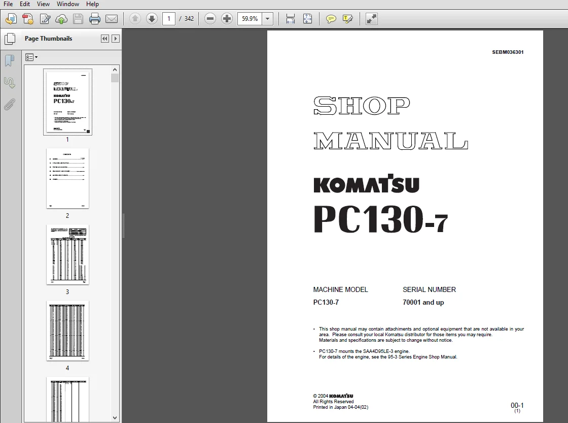
KOMATSU PC130-7 Hydraulic Excavator Service Repair Workshop Manual – PDF Download
Original price was: $62.95.$19.95Current price is: $19.95.
KOMATSU PC130-7 Hydraulic Excavator Service Repair Workshop Manual
Description
KOMATSU PC130-7 Hydraulic Excavator Service Repair Workshop Manual
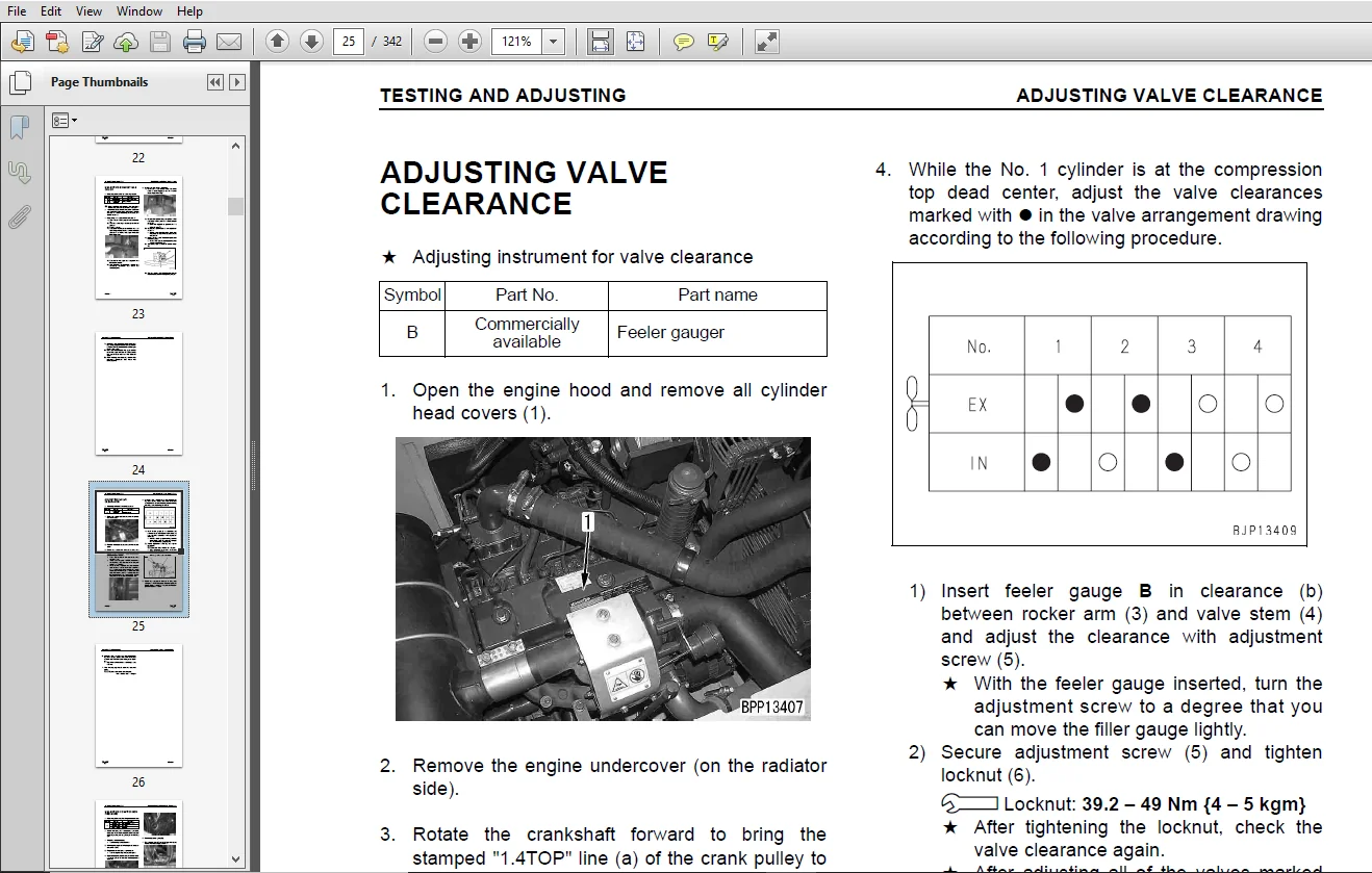
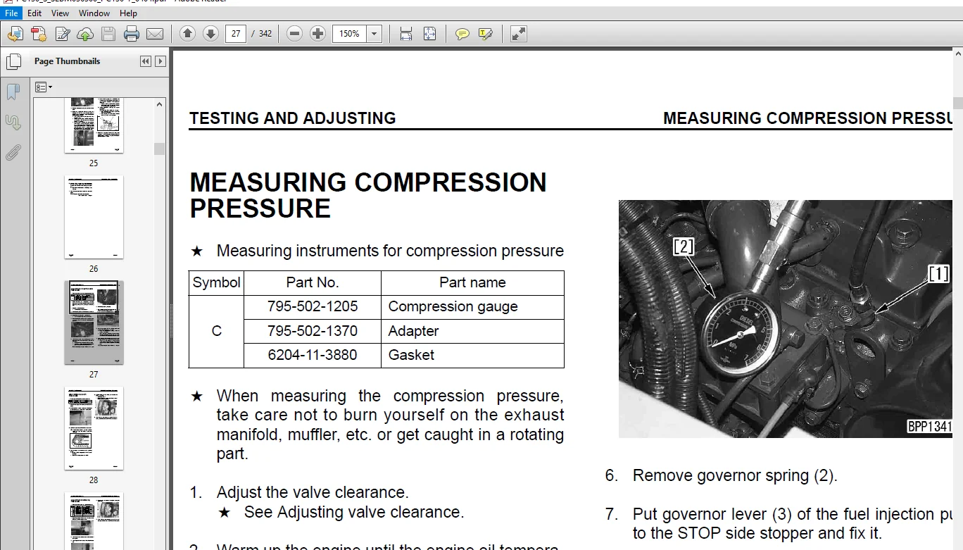
Sample Page From The Manual:
KOMATSU PC130-7 Hydraulic Excavator Service Repair Workshop Manual
1. Procedure for troubleshooting to be taken when user code is displayed on monitor panel:
If a user code is displayed on the monitor panel, display the error code by using the error code display function of the monitor panel. Carry out the troubleshooting for the corresponding “Code display” according to the displayed error code.
2. Procedure for troubleshooting when electrical system error code or mechanical system error code is recorded in error history:
If a user code is not displayed on the monitor panel, check the error code with the error code display function of the monitor panel. If the error code is recorded, carry out troubleshooting for the corresponding “Code display” according to the displayed error code.
a If error codes are recorded, delete all of them and reproduce them, and then see if the trouble is still detected. a If an error code is still output, the mark of “E” is displayed at the left end of the lower line.
3. Procedure for troubleshooting to be taken when user code is not displayed and error history is not recorded:
If a user code is not displayed in the monitor panel and an error code is not recorded, a trouble that the machine cannot find out by itself may have occurred in the electrical system or hydraulic and mechanical system.
In this case, check the phenomenon looking like a trouble again and select the same phenomenon from the table of “Phenomena looking like troubles and troubleshooting Nos.”, and then carry out troubleshooting related to that phenomenon in the “E mode”, “H mode”, or “S mode”.
Table of Contents:
KOMATSU PC130-7 Hydraulic Excavator Service Repair Workshop Manual
20-201--.pdf....................................................................................................................  0
	POINTS TO REMEMBER WHEN TROUBLESHOOTING..................................................................................... 92
		1. When carrying out troubleshooting, do not hurry to disassemble the components........................................ 92
		2. Points to ask user or operator....................................................................................... 92
			1) Have any other problems occurred apart from the problem that has been reported?.................................. 92
			2) Was there anything strange about the machine before the failure occurred?........................................ 92
			3) Did the failure occur suddenly, or were there problems with the machine condition before this?................... 92
			4) Under what conditions did the failure occur?..................................................................... 92
			5) Had any repairs been carried out before the failure?............................................................. 92
			6) Has the same kind of failure occurred before?.................................................................... 92
		3. Check before troubleshooting......................................................................................... 92
			1) Check the oil level.............................................................................................. 92
			2) Check for any external leakage of oil from the piping or hydraulic equipment..................................... 92
			3) Check the travel of the control levers........................................................................... 92
			4) Check the stroke of the control valve spool...................................................................... 92
			5) Other maintenance items can be checked externally, so check any item that is considered to be ................... 92
		4. Confirming failure................................................................................................... 92
		5. Troubleshooting...................................................................................................... 92
			1) Start from the simple points..................................................................................... 92
			2) Start from the most likely points................................................................................ 92
			3) Investigate other related parts or information................................................................... 92
		6. Measures to remove root cause of failure............................................................................. 92
	SEQUENCE OF EVENTS IN TROUBLESHOOTING....................................................................................... 93
	POINTS TO REMEMBER WHEN CARRYING OUT MAINTENANCE............................................................................ 94
		To maintain the performance of the machine over a long period, and to prevent failures or other t....................... 94
			1. Points to remember when handling electric equipment.............................................................. 94
				1) Handling wiring harnesses and connectors..................................................................... 94
					1) Defective contact of connectors (defective contact between male and female).............................. 94
					2) Defective crimping or soldering of connectors............................................................ 94
					3) Disconnections in wiring................................................................................. 95
					4) High-pressure water entering connector................................................................... 95
					5) Oil or dirt stuck to connector........................................................................... 95
				2) Removing, installing, and drying connectors and wiring harnesses............................................. 96
					1) Hold the connectors when disconnecting................................................................... 96
					2) When removing from clips................................................................................. 96
					3) Action to take after removing connectors................................................................. 96
					1) Check the connector visually............................................................................. 97
						1) Check that there is no oil, dirt, or water stuck to the connector pins (mating portion).............. 97
						2) Check that there is no deformation, defective contact, corrosion, or damage to the connector p....... 97
						3) Check that there is no damage or breakage to the outside of the connector............................ 97
					2) Fix the connector securely............................................................................... 97
					3) Correct any protrusion of the boot and any misalignment of the wiring harness............................ 97
					4) If the connector clamp has been removed, be sure to return it to its original position. Check ........... 97
					1) Disconnect the connector and wipe off the water with a dry cloth......................................... 98
					2) Dry the inside of the connector with a dryer............................................................. 98
					3) Carry out a continuity test on the connector............................................................. 98
				3) Handling control box......................................................................................... 99
					1) The control box contains a microcomputer and electronic control circuits. These control all of........... 99
					2) Do not open the cover of the control box unless necessary................................................ 99
					3) Do not place objects on top of the control box........................................................... 99
					4) Cover the control connectors with tape or a vinyl bag.................................................... 99
					5) During rainy weather, do not leave the control box in a place where it is exposed to rain................ 99
					6) Do not place the control box on oil, water, or soil, or in any hot place, even for a short time.......... 99
					7) Precautions when carrying out arc welding................................................................ 99
			2. Points to remember when troubleshooting electric circuits........................................................ 99
				1) Always turn the power OFF before disconnecting or connect connectors......................................... 99
				2) Before carrying out troubleshooting, check that all the related connectors are properly inserted............. 99
				3) Always connect any disconnected connectors before going on to the next step.................................. 99
				4) When carrying out troubleshooting of circuits (measuring the voltage, resistance, continuity, ............... 99
			3. Points to remember when handling hydraulic equipment.............................................................100
		With the increase in pressure and precision of hydraulic equipment, the most common cause of fail.......................100
			1) Be careful of the operating environment..........................................................................100
			2) Disassembly and maintenance work in the field....................................................................100
			3) Sealing openings.................................................................................................100
			4) Do not let any dirt or dust get in during refilling operations...................................................100
			5) Change hydraulic oil when the temperature is high................................................................101
			6) Flushing operations..............................................................................................101
			7) Cleaning operations..............................................................................................101
	Inspection before troubleshooting...........................................................................................102
	Classification of and procedures for troubleshooting........................................................................103
		If a phenomenon looking like a trouble occurs in the machine, select a proper troubleshooting No........................103
			1. Procedure for troubleshooting to be taken when user code is displayed on monitor panel:..........................103
			2. Procedure for troubleshooting when electrical system error code or mechanical system error cod...................103
			3. Procedure for troubleshooting to be taken when user code is not displayed and error history is...................103
	Connector arrangement drawing and electric circuit diagram of each system...................................................107
	CONNECTION TABLE FOR CONNECTOR PIN NUMBERS..................................................................................124
		[The pin No. is also marked on the connector (electric wire insertion end)].............................................138
		[The pin No. is also marked on the connector (electric wire insertion end)].............................................139
		[The pin No. is also marked on the connector (electric wire insertion end)].............................................140
		[The pin No. is also marked on the connector (electric wire insertion end)].............................................141
		[The pin No. is also marked on the connector (electric wire insertion end)].............................................142
		[The pin No. is also marked on the connector (electric wire insertion end)].............................................143
		[The pin No. is also marked on the connector (electric wire insertion end)].............................................144
		8GR: 799-601-9060.......................................................................................................144
		8B: 799-601-9070........................................................................................................144
		8G: 799-601-9080........................................................................................................144
		8BR: 799-601-9090.......................................................................................................144
		12GR: 799-601-9110......................................................................................................144
		12B: 799-601-9120.......................................................................................................144
		12G: 799-601-9130.......................................................................................................144
		12BR: 799-601-9140......................................................................................................144
		[The pin No. is also marked on the connector (electric wire insertion end)].............................................145
		[The pin No. is also marked on the connector (electric wire insertion end)].............................................145
		[The pin No. is also marked on the connector (electric wire insertion end)].............................................146
	T-BRANCH BOX AND T-BRANCH TABLE.............................................................................................147
		TROUBLESHOOTING......................................................................................................... 91
Image Preview:
KOMATSU PC130-7 HYDRAULIC EXCAVATOR SERVICE REPAIR WORKSHOP MANUAL – PDF DOWNLOAD:
Please Note:
⦁ This is the SAME manual used by the dealers to troubleshoot any faults in your vehicle. This can be yours in 2 minutes after the payment is made.
⦁ Contact us at [email protected] should you have any queries before your purchase or that you need any other service / repair / parts operators manual.



