KOMATSU PC138US-11EO HYDRAULIC EXCAVATOR SHOP MANUAL SEN06905-05 – PDF DOWNLOAD
$42.95
KOMATSU PC138US-11EO HYDRAULIC EXCAVATOR SHOP MANUAL SEN06905-05 – PDF DOWNLOAD
Description
KOMATSU PC138US-11EO HYDRAULIC EXCAVATOR SHOP MANUAL SEN06905-05 – PDF DOWNLOAD
FILE DETAILS:
KOMATSU PC138US-11EO HYDRAULIC EXCAVATOR SHOP MANUAL SEN06905-05 – PDF DOWNLOAD
Language : English
Pages : 3490
Downloadable : Yes
File Type : PDF
IMAGES PREVIEW OF THE MANUAL:
TABLE OF CONTENTS:
KOMATSU PC138US-11EO HYDRAULIC EXCAVATOR SHOP MANUAL SEN06905-05 – PDF DOWNLOAD
Index
00 Index and Foreword 00-1
Foreword, Safety, Basic Information 00-19
How to Read the Shop Manual 00-19
Safety Notice for Operation 00-21
Precautions to Prevent Fire 00-29
Procedures If Fire Occurs 00-31
Precautions for Disposing of Waste Materials 00-32
Procedures for Exhaust Gas Regulations 00-33
Precautions for DEF 00-34
Store DEF 00-35
Precautions When You Handle Hydraulic Equipment 00-36
Precautions When You Disconnect and Connect Pipings 00-39
Precautions When You Handle Electrical Equipment 00-46
Precautions When You Handle Fuel System Equipment 00-48
Precautions When You Handle Intake System Equipment 00-49
Practical Use of KOMTRAX 00-50
Disconnect and Connect Push-Pull Type Coupler 00-51
Precautions for Disconnection and Connection of Connectors 00-55
How to Disconnect and Connect Deutsch Connector 00-59
How to Disconnect and Connect Slide Lock Type Connector 00-60
How to Disconnect and Connect Connector with Lock to Pull 00-62
How to Disconnect and Connect Connector with Lock to Push 00-63
How to Disconnect and Connect Connector with Housing to Rotate 00-65
How to Read the Codes for Electric Cable 00-66
Explanation of Terms for Maintenance Standard 00-70
Standard Tightening Torque Table 00-73
Conversion Table 00-80
Abbreviation List 00-85
01 Specifications 01-1
Table of Contents 01-2
Specifications 01-3
Specification Drawing 01-3
Working Range Drawings 01-5
Specifications 01-6
Weight Table 01-10
Fuel, Coolant, Lubricant 01-12
10 Structure and Function 10-1
Table of Contents 10-2
Urea SCR System 10-5
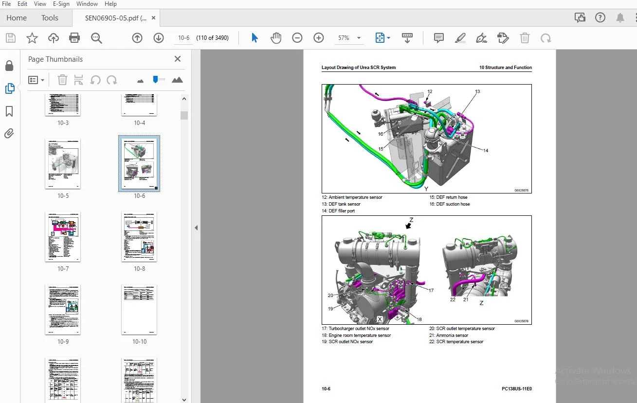
Layout Drawing of Urea SCR System 10-5
Urea SCR System Diagram 10-7
Function of Urea SCR System 10-8
Component Parts of Urea SCR System 10-19
Boot-up System 10-28
Layout Drawing of Boot-up System 10-28
System Operating Lamp System 10-29
Battery Disconnect Switch 10-30
Engine System 10-31
Layout Drawing of Engine System 10-31
Engine Control System 10-33
Auto-Deceleration System 10-36
Engine Automatic Warm-up System 10-38
Overheat Prevention System 10-40
Turbocharger Protection System 10-42
Automatic Idle Stop System 10-43
Component Parts of Engine System 10-46
Index 00 Index and Foreword
00-2 PC138US-11E0
Cooling System 10-68
Layout Drawing of Cooling System 10-68
Fan Speed Control System of Fan Clutch 10-70
Engine Output Control System of Fan Clutch 10-72
Component Parts of Cooling System 10-74
Control System 10-75
Layout Drawing of Control System 10-75
Machine Monitor System 10-77
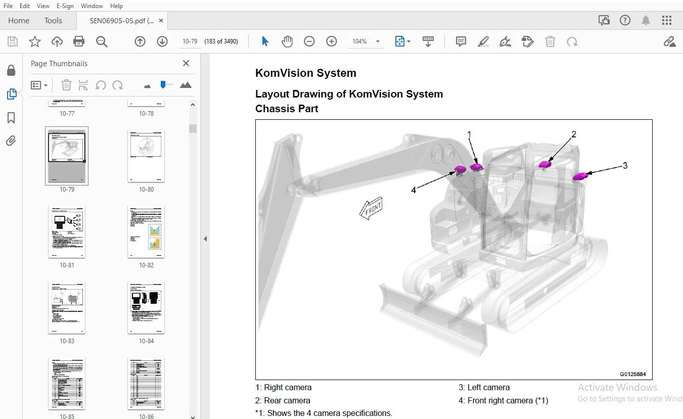
KomVision System 10-79
KOMTRAX System 10-83
Component Parts of Control System 10-84
Hydraulic System 10-127
Layout Drawing of Hydraulic System 10-127
CLSS 10-129
Engine and Pump Combined Control System 10-132
Component Parts of Hydraulic System 10-137
Work Equipment System 10-226
Layout Drawing of Work Equipment System 10-226
Structure of Valve Control 10-229
PPC Lock System 10-230
Work Equipment and Travel Automatic Lock System 10-231
Attachment Oil Flow Adjuster System 10-233
Tool Control System 10-235
Component Parts of Work Equipment System 10-237
Swing System 10-264
Layout Drawing of Swing System 10-264
Swing Control System Diagram 10-266
Component Parts of Swing System 10-269
Travel System 10-282
Layout Drawing of Travel System 10-282
System Diagram of Travel Control System 10-284
Component Parts of Travel System 10-288
Undercarriage and Frame 10-304
Layout Drawing of Undercarriage 10-304
Idler Cushion 10-305
Work Equipment 10-306
Structure of Work Equipment 10-306
Function of Work Equipment 10-307
Work Equipment Clearance Adjustment Shim 10-308
Bucket Clearance Adjustment Shim 10-309
CAB Related Parts 10-310
ROPS CAB 10-310
CAB Mount 10-311
Remove Wiring Harness Out of Cab 10-313
20 Standard Value Table 20-1
Table of Contents 20-2
Standard Value Table for Engine 20-3
Standard Value Table for Engine: PC138US-11E0 20-3
Standard Value Table for Machine 20-7
Standard Value Table for Machine: PC138US-11E0 20-7
Machine Posture and Procedures to Measure Performance 20-21
30 Testing and Adjusting 30-1
Table of Contents 30-2
Precautions Before Work 30-5
Related Information on Testing and Adjusting 30-6
Differences In Machine Monitor Symbols 30-6
Tools for Testing and Adjusting 30-7
Sketch of Tools for Testing and Adjusting 30-14
00 Index and Foreword Index
PC138US-11E0 00-3
Engine and Cooling System 30-16
Examine Engine Speed 30-16
Examine Exhaust Gas Color 30-19
Examine the Clearance of Exhaust Throttle Valve 30-22
Examine and Adjust Valve Clearance 30-25
Examine Compression Pressure 30-27
Examine Blowby Pressure 30-30
Examine Engine Oil Pressure 30-32
Visual Check Inside of EGR Valve 30-34
Clean Inside of EGR Valve 30-36
Examine Fuel Pressure 30-39
Examine Fuel Return Rate and Leakage 30-41
Bleed Air from Fuel System 30-45
Examine Fuel Circuit for Leakage 30-47
Handle Cylinder Cut-out Mode Operation 30-49
Handle No-Injection Cranking Operation 30-50
Examine and Adjust Air Conditioner Compressor Belt Tension 30-51
Examine Alternator Belt 30-53
Examine Automatic Tensioner 30-54
Examine Cooling Fan Speed 30-56
Write Correction for Ash in Soot Accumulation to Engine Controller 30-57
Write Injector Compensation Value to Engine Controller 30-58
Examine SCR Related Functions 30-64
Clean DEF Tank 30-94
Bleed Air from Coolant Circuit of DEF Tank 30-99
Clean DEF Pump 30-101
Power Train 30-107
Examine Swing Circle Bearing Clearance 30-107
Undercarriage and Frame 30-108
Examine and Adjust Track Tension 30-108
Hydraulic System 30-110
Release Remained Pressure in Hydraulic Circuit 30-110
Examine and Adjust Oil Pressure in Work Equipment, Swing, Travel, and Blade Circuits 30-113
Examine Oil Pressure of Control Circuit 30-122
Examine and adjust oil pressure in pump PC control circuit 30-124
Examine and Adjust Oil Pressure in Pump LS Control Circuit 30-128
Examine Outlet Pressure of Solenoid Valve 30-134
Examine PPC Valve Outlet Pressure 30-139
Examine Attachment Circuit Oil Pressure 30-141
Adjust Play of Work Equipment and Swing PPC Valves 30-142
Examine and Adjust Travel Deviation 30-143
Examine Parts Which Cause Hydraulic Drift of Work Equipment 30-146
Examine Oil Leakage 30-148
Bleed Air from Hydraulic System 30-152
Examine and Charge Accumulator (Made by Eagle Industry Co , Ltd ) Nitrogen Gas Pressure for Attachment
30-156
CAB Related Parts 30-160
Examine CAB Tipping Stopper 30-160
Adjust Mirrors 30-161
How to Examine and Adjust Slide Door 30-163
Electrical System 30-188
Set and Operate Machine Monitor 30-188
How to Start Up KOMTRAX System 30-281
How to Stop Use of KOMTRAX System 30-287
Adjust KomVision Camera Angle 30-289
Adjust KomVision Related Function 30-293
Set Region of Bluetooth® Compatible Radio 30-312
Handle Voltage Circuit of Engine Controller 30-314
Index 00 Index and Foreword
00-4 PC138US-11E0
Handle Battery Disconnect Switch 30-315
Examine Diodes 30-316
Pm Clinic 30-317
Pm Clinic Service 30-317
40 Troubleshooting 40-1
Table of Contents 40-2
Precautions Before Work 40-13
Related Information to Troubleshooting 40-14
General Troubleshooting Points 40-14
Troubleshooting Points for Aftertreatment System 40-15
Sequence of Events in Troubleshooting 40-27
Checks Before Troubleshooting 40-29
Inspection Procedure Before Troubleshooting 40-31
Test in Accordance with Testing Procedure 40-33
Preparation for Troubleshooting of Electrical System 40-53
Procedure for Troubleshooting 40-60
Symptom and Troubleshooting Numbers 40-63
Information Shown in Troubleshooting Table 40-68
How to Diagnose Open Circuit of Hydraulic Pressure Sensor System Wiring Harness 40-70
Connector List and Layout 40-73
Connector Contact Connection Table 40-87
T-Branch Box and T-Branch Adapter Table 40-127
Fuse Location Table 40-133
Precautions When You Clean and Replace KDPF (KCSF and KDOC) 40-136
Prepare Short Circuit Electrical Connector (For Failure Codes [CA1883] and [CA3135]) 40-140
Failure Code Table 40-142
Troubleshooting by Failure Code (Display of Code) 40-161
Failure Code [6AZ0ZG] 40-161
Failure Code [879AKA] 40-163
Failure Code [879AKB] 40-165
Failure Code [879BKA] 40-167
Failure Code [879BKB] 40-169
Failure Code [879CKA] 40-171
Failure Code [879CKB] 40-172
Failure Code [879DKZ] 40-173
Failure Code [879EMC] 40-176
Failure Code [879FMC] 40-177
Failure Code [879GKX] 40-178
Failure Code [989L00] 40-180
Failure Code [989M00] 40-181
Failure Code [989N00] 40-182
Failure Code [A1U0N3] 40-183
Failure Code [A1U0N4] 40-185
Failure Code [A900FR] 40-187
Failure Code [A900N6] 40-188
Failure Code [A900NY] 40-189
Failure Code [AA10NX] 40-190
Failure Code [AB00KE] 40-192
Failure Code [AQ10MB] 40-195
Failure Code [AQ10N3] 40-197
Failure Code [AS00R2] 40-199
Failure Code [AS00R3] 40-200
Failure Code [AS00R4] 40-201
Failure Code [AS00R6] 40-202
Failure Code [AS10KM] 40-203
Failure Code [AS10NR] 40-204
Failure Code [AS10NT] 40-205
Failure Code [AU10QA] 40-206
00 Index and Foreword Index
PC138US-11E0 00-5
Failure Code [B@BAZG] 40-207
Failure Code [B@BAZK] 40-208
Failure Code [B@BCNS] 40-210
Failure Code [B@BCQA] 40-211
Failure Code [B@BCZK] 40-213
Failure Code [B@HANS] 40-215
Failure Code [CA115] 40-217
Failure Code [CA122] 40-219
Failure Code [CA123] 40-223
Failure Code [CA131] 40-227
Failure Code [CA132] 40-230
Failure Code [CA144] 40-233
Failure Code [CA145] 40-237
Failure Code [CA153] 40-240
Failure Code [CA154] 40-244
Failure Code [CA187] 40-248
Failure Code [CA221] 40-250
Failure Code [CA222] 40-254
Failure Code [CA227] 40-257
Failure Code [CA234] 40-258
Failure Code [CA238] 40-260
Failure Code [CA239] 40-262
Failure Code [CA249] 40-264
Failure Code [CA256] 40-267
Failure Code [CA271] 40-270
Failure Code [CA272] 40-273
Failure Code [CA322] 40-275
Failure Code [CA324] 40-279
Failure Code [CA331] 40-283
Failure Code [CA332] 40-287
Failure Code [CA343] 40-291
Failure Code [CA351] 40-292
Failure Code [CA352] 40-293
Failure Code [CA356] 40-296
Failure Code [CA357] 40-299
Failure Code [CA386] 40-303
Failure Code [CA435] 40-304
Failure Code [CA441] 40-306
Failure Code [CA442] 40-309
Failure Code [CA449] 40-310
Failure Code [CA451] 40-311
Failure Code [CA452] 40-314
Failure Code [CA515] 40-317
Failure Code [CA516] 40-319
Failure Code [CA553] 40-322
Failure Code [CA555] 40-324
Failure Code [CA556] 40-326
Failure Code [CA559] 40-328
Failure Code [CA689] 40-334
Failure Code [CA691] 40-339
Failure Code [CA692] 40-342
Failure Code [CA697] 40-345
Failure Code [CA698] 40-346
Failure Code [CA731] 40-347
Failure Code [CA778] 40-350
Failure Code [CA1117] 40-357
Failure Code [CA1664] 40-359
Failure Code [CA1669] 40-362
Index 00 Index and Foreword
00-6 PC138US-11E0
Failure Code [CA1673] 40-364
Failure Code [CA1677] 40-366
Failure Code [CA1678] 40-368
Failure Code [CA1682] 40-370
Failure Code [CA1683] 40-373
Failure Code [CA1684] 40-376
Failure Code [CA1686] 40-379
Failure Code [CA1691] 40-381
Failure Code [CA1694] 40-384
Failure Code [CA1695] 40-386
Failure Code [CA1696] 40-387
Failure Code [CA1712] 40-390
Failure Code [CA1713] 40-393
Failure Code [CA1714] 40-395
Failure Code [CA1715] 40-397
Failure Code [CA1776] 40-399
Failure Code [CA1777] 40-402
Failure Code [CA1843] 40-406
Failure Code [CA1844] 40-409
Failure Code [CA1883] 40-413
Failure Code [CA1885] 40-418
Failure Code [CA1887] 40-421
Failure Code [CA1896] 40-424
Failure Code [CA1921] 40-428
Failure Code [CA1922] 40-432
Failure Code [CA1938] 40-437
Failure Code [CA1942] 40-440
Failure Code [CA1961] 40-442
Failure Code [CA1993] 40-443
Failure Code [CA2185] 40-448
Failure Code [CA2186] 40-450
Failure Code [CA2249] 40-452
Failure Code [CA2272] 40-453
Failure Code [CA2311] 40-457
Failure Code [CA2349] 40-458
Failure Code [CA2353] 40-461
Failure Code [CA2357] 40-464
Failure Code [CA2636] 40-465
Failure Code [CA2637] 40-469
Failure Code [CA2639] 40-471
Failure Code [CA2765] 40-473
Failure Code [CA2771] 40-474
Failure Code [CA2777] 40-482
Failure Code [CA2976] 40-485
Failure Code [CA3135] 40-489
Failure Code [CA3142] 40-492
Failure Code [CA3143] 40-493
Failure Code [CA3144] 40-494
Failure Code [CA3146] 40-497
Failure Code [CA3147] 40-498
Failure Code [CA3148] 40-499
Failure Code [CA3151] 40-502
Failure Code [CA3165] 40-508
Failure Code [CA3229] 40-511
Failure Code [CA3231] 40-514
Failure Code [CA3232] 40-516
Failure Code [CA3235] 40-521
Failure Code [CA3239] 40-524
00 Index and Foreword Index
PC138US-11E0 00-7
Failure Code [CA3241] 40-528
Failure Code [CA3242] 40-532
Failure Code [CA3251] 40-535
Failure Code [CA3255] 40-538
Failure Code [CA3256] 40-541
Failure Code [CA3312] 40-543
Failure Code [CA3313] 40-546
Failure Code [CA3314] 40-548
Failure Code [CA3315] 40-549
Failure Code [CA3318] 40-551
Failure Code [CA3322] 40-553
Failure Code [CA3419] 40-555
Failure Code [CA3421] 40-557
Failure Code [CA3497] 40-559
Failure Code [CA3498] 40-560
Failure Code [CA3545] 40-561
Failure Code [CA3547] 40-564
Failure Code [CA3558] 40-566
Failure Code [CA3559] 40-569
Failure Code [CA3562] 40-572
Failure Code [CA3563] 40-575
Failure Code [CA3567] 40-580
Failure Code [CA3568] 40-584
Failure Code [CA3571] 40-588
Failure Code [CA3572] 40-591
Failure Code [CA3574] 40-594
Failure Code [CA3575] 40-597
Failure Code [CA3577] 40-599
Failure Code [CA3578] 40-602
Failure Code [CA3582] 40-605
Failure Code [CA3583] 40-611
Failure Code [CA3596] 40-614
Failure Code [CA3649] 40-617
Failure Code [CA3681] 40-620
Failure Code [CA3682] 40-627
Failure Code [CA3713] 40-634
Failure Code [CA3717] 40-638
Failure Code [CA3718] 40-640
Failure Code [CA3724] 40-642
Failure Code [CA3725] 40-643
Failure Code [CA3748] 40-646
Failure Code [CA3755] 40-648
Failure Code [CA3866] 40-650
Failure Code [CA3867] 40-655
Failure Code [CA3868] 40-659
Failure Code [CA3899] 40-664
Failure Code [CA3911] 40-667
Failure Code [CA3912] 40-672
Failure Code [CA3918] 40-675
Failure Code [CA3921] 40-678
Failure Code [CA3928] 40-683
Failure Code [CA3932] 40-684
Failure Code [CA3933] 40-687
Failure Code [CA3934] 40-690
Failure Code [CA3935] 40-694
Failure Code [CA3936] 40-697
Failure Code [CA4152] 40-699
Failure Code [CA4155] 40-704
Index 00 Index and Foreword
00-8 PC138US-11E0
Failure Code [CA4156] 40-707
Failure Code [CA4157] 40-711
Failure Code [CA4159] 40-713
Failure Code [CA4164] 40-715
Failure Code [CA4165] 40-718
Failure Code [CA4166] 40-721
Failure Code [CA4168] 40-723
Failure Code [CA4169] 40-725
Failure Code [CA4171] 40-727
Failure Code [CA4249] 40-730
Failure Code [CA4251] 40-732
Failure Code [CA4261] 40-734
Failure Code [CA4277] 40-738
Failure Code [CA4281] 40-742
Failure Code [CA4459] 40-745
Failure Code [CA4461] 40-748
Failure Code [CA4533] 40-753
Failure Code [CA4534] 40-754
Failure Code [CA4731] 40-756
Failure Code [CA4732] 40-758
Failure Code [CA4739] 40-760
Failure Code [CA4768] 40-762
Failure Code [CA4769] 40-765
Failure Code [CA4842] 40-768
Failure Code [CA4952] 40-773
Failure Code [CA5115] 40-775
Failure Code [CA5179] 40-779
Failure Code [CA5181] 40-782
Failure Code [CA5271] 40-785
Failure Code [CA5272] 40-788
Failure Code [CA5273] 40-791
Failure Code [CA5274] 40-794
Failure Code [CA5275] 40-796
Failure Code [CA5276] 40-799
Failure Code [CA5277] 40-802
Failure Code [CA5383] 40-804
Failure Code [CA5387] 40-806
Failure Code [CA5388] 40-808
Failure Code [CA5389] 40-811
Failure Code [CA5391] 40-813
Failure Code [CA5392] 40-819
Failure Code [CA5393] 40-821
Failure Code [CA5394] 40-824
Failure Code [CA5395] 40-827
Failure Code [CA5396] 40-830
Failure Code [CA5631] 40-832
Failure Code [CA5938] 40-834
Failure Code [D110KB] 40-836
Failure Code [D19JKZ] 40-838
Failure Code [D811MC] 40-841
Failure Code [D862KA] 40-842
Failure Code [D8ALKA] 40-844
Failure Code [D8ALKB] 40-847
Failure Code [D8AQKR] 40-849
Failure Code [D8ARKR] 40-854
Failure Code [D8G1KT] 40-859
Failure Code [D8G6KT] 40-860
Failure Code [DA20MC] 40-861
00 Index and Foreword Index
PC138US-11E0 00-9
Failure Code [DA22KK] 40-862
Failure Code [DA22KT] 40-866
Failure Code [DA25KP] 40-869
Failure Code [DA26KP] 40-874
Failure Code [DA29KQ] 40-877
Failure Code [DA2JKT] 40-880
Failure Code [DA2JKY] 40-881
Failure Code [DA2LKA] 40-882
Failure Code [DA2LKB] 40-885
Failure Code [DA2QKR] 40-887
Failure Code [DA2RKR] 40-894
Failure Code [DAF0KM] 40-901
Failure Code [DAF0MB] 40-902
Failure Code [DAF0MC] 40-903
Failure Code [DAF8KB] 40-904
Failure Code [DAF9KQ] 40-906
Failure Code [DAFGMC] 40-908
Failure Code [DAFLKA] 40-909
Failure Code [DAFLKB] 40-912
Failure Code [DAFQKR] 40-914
Failure Code [DAZ9KQ] 40-920
Failure Code [DAZQKR] 40-922
Failure Code [DB2QKR] 40-927
Failure Code [DB2RKR] 40-934
Failure Code [DBP0KM] 40-942
Failure Code [DBP0KT] 40-943
Failure Code [DBP5KB] 40-944
Failure Code [DBP5KY] 40-947
Failure Code [DBPQKR] 40-950
Failure Code [DDNRKA] 40-956
Failure Code [DDNRKY] 40-959
Failure Code [DDNS00] 40-962
Failure Code [DFB1KZ] 40-965
Failure Code [DFB2KZ] 40-968
Failure Code [DFB3L8] 40-971
Failure Code [DFB4L8] 40-973
Failure Code [DFB5KZ] 40-975
Failure Code [DFB6KZ] 40-978
Failure Code [DGH2KA] 40-981
Failure Code [DGH2KB] 40-983
Failure Code [DHA4KA] 40-985
Failure Code [DHAAMA] 40-987
Failure Code [DHACMA] 40-989
Failure Code [DHPAMA] 40-991
Failure Code [DHS3MA] 40-994
Failure Code [DHS4MA] 40-997
Failure Code [DHS8MA] 40-1000
Failure Code [DHS9MA] 40-1003
Failure Code [DHSAMA] 40-1006
Failure Code [DHSBMA] 40-1009
Failure Code [DHSCMA] 40-1012
Failure Code [DHSDMA] 40-1015
Failure Code [DHSFMA] 40-1018
Failure Code [DHSGMA] 40-1021
Failure Code [DHSHMA] 40-1024
Failure Code [DHSJMA] 40-1027
Failure Code [DHSKMA] 40-1030
Failure Code [DHSLMA] 40-1032
Index 00 Index and Foreword
00-10 PC138US-11E0
Failure Code [DHX1MA] 40-1034
Failure Code [DKULKA] 40-1035
Failure Code [DKULKB] 40-1037
Failure Code [DKULKY] 40-1040
Failure Code [DLM5KA] 40-1042
Failure Code [DLM5MB] 40-1046
Failure Code [DR10KA] 40-1048
Failure Code [DR12KA] 40-1053
Failure Code [DR20KA] 40-1055
Failure Code [DR21KX] 40-1057
Failure Code [DR30KA] 40-1058
Failure Code [DR31KX] 40-1060
Failure Code [DR40KA] 40-1061
Failure Code [DUMBKA] 40-1063
Failure Code [DUMBKB] 40-1066
Failure Code [DV00KA] 40-1068
Failure Code [DV00KB] 40-1069
Failure Code [DV20KB] 40-1070
Failure Code [DW43KA] 40-1072
Failure Code [DW43KB] 40-1074
Failure Code [DW43KY] 40-1076
Failure Code [DW45KA] 40-1078
Failure Code [DW45KB] 40-1082
Failure Code [DW45KY] 40-1086
Failure Code [DW4CKY] 40-1088
Failure Code [DW91KA] 40-1090
Failure Code [DW91KB] 40-1092
Failure Code [DW91KY] 40-1094
Failure Code [DWA2KA] 40-1096
Failure Code [DWA2KB] 40-1098
Failure Code [DWA2KY] 40-1100
Failure Code [DWJ0KA] 40-1102
Failure Code [DWJ0KB] 40-1104
Failure Code [DWJ0KY] 40-1106
Failure Code [DWK2KA] 40-1108
Failure Code [DWK2KB] 40-1110
Failure Code [DWK2KY] 40-1112
Failure Code [DWN5KA] 40-1114
Failure Code [DWN5KB] 40-1117
Failure Code [DWN5KY] 40-1119
Failure Code [DWNSKA] 40-1121
Failure Code [DWNSKB] 40-1123
Failure Code [DWNSKY] 40-1125
Failure Code [DXA8KA] 40-1127
Failure Code [DXA8KB] 40-1131
Failure Code [DXE4KA] 40-1134
Failure Code [DXE4KB] 40-1136
Failure Code [DXE4KY] 40-1138
Failure Code [DXE7KA] 40-1140
Failure Code [DXE7KB] 40-1142
Failure Code [DXE7KY] 40-1144
Failure Code [DXE8KA] 40-1146
Failure Code [DXE8KB] 40-1148
Failure Code [DXE8KY] 40-1150
Failure Code [DXE9KA] 40-1152
Failure Code [DXE9KB] 40-1154
Failure Code [DXE9KY] 40-1156
Failure Code [DXEAKA] 40-1158
00 Index and Foreword Index
PC138US-11E0 00-11
Failure Code [DXEAKB] 40-1160
Failure Code [DXEAKY] 40-1162
Failure Code [DXEKKA] 40-1164
Failure Code [DXEKKB] 40-1166
Failure Code [DXEKKY] 40-1168
Failure Code [DXELKA] 40-1170
Failure Code [DXELKB] 40-1172
Failure Code [DXELKY] 40-1174
Failure Code [DY20KA] 40-1176
Failure Code [DY20MA] 40-1179
Failure Code [DY2CKB] 40-1182
Failure Code [DY2DKB] 40-1186
Failure Code [DY2EKB] 40-1189
Failure Code [F311KA] 40-1192
Failure Code [F311KB] 40-1194
Failure Code [F312KA] 40-1196
Failure Code [F312KB] 40-1198
Failure Code [F313KA] 40-1200
Failure Code [F313KB] 40-1202
Failure Code [F314KA] 40-1204
Failure Code [F314KB] 40-1206
Failure Code [F315KB] 40-1208
Failure Code [F315KY] 40-1210
Failure Code [F316KB] 40-1212
Failure Code [F316KY] 40-1214
Failure Code [F318KB] 40-1216
Failure Code [F318KY] 40-1218
Failure Code [F31AKB] 40-1220
Failure Code [F31AKY] 40-1222
Failure Code [F31BKB] 40-1224
Failure Code [F31BKY] 40-1226
Failure Code [F31CKB] 40-1228
Failure Code [F31CKY] 40-1230
Failure Code [F31DKB] 40-1232
Failure Code [F31DKY] 40-1234
Failure Code [F31EKB] 40-1236
Failure Code [F31EKY] 40-1238
Failure Code [FS10ZE] 40-1240
Troubleshooting of Electrical System (E-Mode) 40-1241
E-1 Engine Does Not Start (Engine Does Not Crank) 40-1241
E-2 Manual Preheating System Does Not Operate 40-1247
E-3 While Preheating is in Operation, Preheating Monitor Does Not Come On 40-1250
E-4 When Starting Switch is Turned to ON Position, Machine Monitor Shows Nothing 40-1252
E-5 Engine Coolant Temperature Monitor Comes On in White While Engine is in Operation 40-1255
E-6 Hydraulic Oil Temperature Monitor Comes On in White While Engine is in Operation 40-1256
E-7 Air Cleaner Clogging Monitor Comes On in Yellow While Engine is in Operation 40-1257
E-8 Charge Level Monitor Comes On in Red While Engine is in Operation 40-1258
E-9 Fuel Level Monitor Comes On in Red While Engine is in Operation 40-1259
E-10 Engine Coolant Temperature Monitor Comes On in Red While Engine is in Operation 40-1260
E-11 Engine Oil Pressure Monitor Comes On in Red While Engine is in Operation 40-1261
E-12 Hydraulic Oil Temperature Monitor Comes On in Red While Engine is in Operation 40-1262
E-13 Fuel Gauge Does Not Move from Minimum or Maximum 40-1263
E-14 Display of Fuel Gauge is Different from Actual Fuel Level 40-1265
E-15 Engine Coolant Temperature Gauge Display Does Not Move from Minimum or Maximum 40-1266
E-16 Display of Engine Coolant Temperature Gauge is Different from Actual Coolant Temperature
40-1267
E-17 DEF Level is Not Shown Correctly 40-1268
E-18 Hydraulic Oil Temperature Gauge Does Not Move from Minimum or Maximum 40-1271
Index 00 Index and Foreword
00-12 PC138US-11E0
E-19 Display of Hydraulic Oil Temperature Gauge is Different from Actual Oil Temperature 40-1273
E-20 Some Areas of Machine Monitor Screen are Not Shown 40-1274
E-21 Function Switch Does Not Operate 40-1275
E-22 Automatic Warm-up System Does Not Operate (in Cold Weather) 40-1276
E-23 Auto-Deceleration Monitor Does Not Come On or Go Out While Auto-Deceleration Switch is Operated
40-1277
E-24 Auto-Decelerator is Not Operated or Canceled with Lever 40-1278
E-25 Work Mode Selector Screen is Not Shown While Work Mode Switch is Operated 40-1279
E-26 When Working Mode is Changed, Setting of Engine and Hydraulic Pump is Not Changed 40-1280
E-27 Travel Speed Monitor Does Not Change While Travel Speed Switch is Operated 40-1281
E-28 Travel Speed Does Not Change Even When You Change Travel Speed 40-1282
E-29 Alarm Buzzer Does Not Stop 40-1283
E-30 Service Meter is Not Shown While Starting Switch is in OFF Position 40-1284
E-31 Service Mode Cannot be Selected 40-1285
E-32 All Work Equipment, Swing, Travel Do Not Operate 40-1286
E-33 All Work Equipment, Swing, Travel Cannot be Locked 40-1289
E-34 Machine Does Not Swing While Swing Parking Brake Release Switch is Set to Release Position
40-1291
E-35 While Swing Parking Brake Release Switch is Turned on, Swing Brake is Not Operated 40-1293
E-36 Work Equipment Does Not Operate While Lock Lever Automatic Release Switch is in Release
Position 40-1295
E-37 Travel Alarm Does Not Operate During Travel 40-1297
E-38 Travel Alarm Does Not Stop When Machine Stops 40-1299
E-39 Horn Does Not Sound 40-1300
E-40 Horn Does Not Stop 40-1302
E-41 Wiper Monitor Does Not Come On or Go Out While Wiper Switch is Operated 40-1303
E-42 Windshield Wiper Does Not Operate When Wiper Switch is Operated 40-1304
E-43 When Window Washer Switch is Operated, Window Washer Does Not Operate 40-1306
E-44 “Boom Raise” is Not Shown Correctly with Monitoring Function 40-1307
E-45 “Boom Lower” is Not Shown Correctly with Monitoring Function 40-1308
E-46 “Arm OUT” is Not Shown Correctly with Monitoring Function 40-1309
E-47 “Arm IN” is Not Shown Correctly with Monitoring Function 40-1310
E-48 Bucket DUMP is Not Shown Correctly with Monitoring Function 40-1311
E-49 Bucket CURL is Not Shown Correctly with Monitoring Function 40-1312
E-50 Swing is Not Shown Correctly with Monitoring Function 40-1313
E-51 Travel is Not Shown Correctly with Monitoring Function 40-1314
E-52 Service is Not Shown Correctly with Monitoring Function 40-1315
E-53 Blade RAISE is Not Shown Correctly with Monitoring Function 40-1318
E-54 Blade LOWER is Not Shown Correctly with Monitoring Function 40-1319
E-55 KOMTRAX System Does Not Operate Correctly 40-1320
Troubleshooting for Hydraulic and Mechanical Systems (H Mode) 40-1321
Information Shown in Troubleshooting Table (H-Mode) 40-1321
Failure Mode and Cause Table 40-1322
H-1 All Work Equipment, Swing and Travel Do Not Work 40-1331
H-2 All Work Equipment, Swing, and Travel Lack Speed or Power 40-1332
H-3 Fine Control Performance or Response is Unsatisfactory 40-1334
H-4 Unusual Noise is Heard from Around Hydraulic Pump 40-1335
H-5 Engine Speed Drops Largely or Engine Stops 40-1336
H-6 Boom Speed or Power is Low 40-1338
H-7 Arm Speed or Power is Low 40-1341
H-8 Bucket Speed or Power is Low 40-1344
H-9 Blade Speed or Power is Low 40-1347
H-10 Work Equipment Does Not Move in Single Operation 40-1349
H-11 Hydraulic Drift of Boom is Large 40-1350
H-12 Hydraulic Drift of Arm is Large 40-1351
H-13 Hydraulic Drift of Bucket is Large 40-1352
H-14 Hydraulic Drift of Blade is Large 40-1353
H-15 When Single Work Equipment is Released Hydraulically, Other Work Equipment Moves 40-1355
00 Index and Foreword Index
PC138US-11E0 00-13
H-16 Time Lag of Work Equipment is Large 40-1356
H-17 Attachment Circuit Cannot be Changed 40-1357
H-18 Oil Flow in Attachment Circuit Cannot be Changed 40-1358
H-19 In Mixed Operation of Work Equipment, Work Equipment with Heavier Load Moves Slower40-1359
H-20 In Mixed Operation of Swing and Travel, Travel Speed Falls Largely 40-1360
H-21 In Mixed Operation of Swing and Boom RAISE, Boom RAISE Speed is Low 40-1361
H-22 Machine Does Not Travel Straight 40-1362
H-23 Machine is Not Steered Well or Steering Power is Low 40-1365
H-24 Travel Speed is Low 40-1367
H-25 One of Tracks Does Not Run 40-1369
H-26 Travel Speed Does Not Change, or Travel Speed is Too Slow or Fast 40-1371
H-27 Upper Structure Does Not Swing in Two Directions of Right and Left 40-1372
H-28 Machine Swings Only in One Direction 40-1373
H-29 Swing Acceleration or Swing Speed is Low in Two Directions of Right and Left 40-1374
H-30 Swing Acceleration or Swing Speed is Low in Only One Direction 40-1375
H-31 Upper Structure Overruns Too Much When It Stops Swing Operation (Right and Left) 40-1376
H-32 Upper Structure Overruns Too Much When It Stops Swing Operation (Only One Direction)40-1377
H-33 Shock is Large When Upper Structure Stops Swing Operation 40-1378
H-34 Large Unusual Noise is Made When Upper Structure Stops Swing Operation 40-1379
H-35 Swing Drift on a Slope is Large (While Swing Parking Brake is Applied) 40-1380
H-36 Swing Drift on a Slope is Large (While Swing Parking Brake is Released) 40-1381
H-37 Fan Speed is Abnormal (Too High or Low, or Does Not Rotate) 40-1382
H-38 Unusual Noise is Heard from Around Fan 40-1383
Troubleshooting of Engine (S-Mode) 40-1384
Information Shown in Troubleshooting Table (S-Mode) 40-1384
S-1 Engine Does Not Crank When Starting Switch is Turned to Start Position 40-1385
S-2 Engine Cranks but No Exhaust Smoke Comes Out 40-1386
S-3 Fuel is Sprayed but Engine Does Not Start (Misfiring: Engine Cranks but Does Not Start) 40-1387
S-4 Engine Startability is Unsatisfactory 40-1388
S-5 Engine Does Not Pick Up Smoothly 40-1390
S-6 Engine Stops During Operation 40-1392
S-7 Engine Does Not Rotate Smoothly 40-1394
S-8 Engine Lacks Output (or Lacks Power) 40-1395
S-9 Exhaust Color is Black (KDPF Becomes Clogged in Short Time) 40-1397
S-10 Engine Oil Consumption is Excessive 40-1399
S-11 Engine Oil Becomes Dirty Quickly 40-1400
S-12 Fuel Consumption is Excessive 40-1401
S-13 Oil is in Coolant (or Coolant Spurts Back or Coolant Level Goes Down) 40-1402
S-14 Engine Oil Pressure Drops 40-1403
S-15 Fuel Mixes Into Engine Oil 40-1404
S-16 Water Mixes Into Engine Oil (Milky) 40-1405
S-17 Coolant Temperature Increases Too High (Overheat) 40-1406
S-18 Unusual Noise is Heard 40-1407
S-19 Vibration is Excessive 40-1409
S-20 Air Cannot be Bled from Fuel Circuit 40-1410
S-21 Active Regeneration is Done Frequently 40-1411
S-22 Active Regeneration Continues Long 40-1412
S-23 White Smoke is Exhausted During Active Regeneration 40-1413
S-24 DEF Consumption is Excessive 40-1414
S-25 There is an Unusual Smell (Irritating Odor) 40-1416
S-26 Foreign Materials Enter DEF (DEF Increases) 40-1417
50 Disassembly and Assembly 50-1
Table of Contents 50-2
Precautions Before Work 50-7
Related Information on Disassembly and Assembly 50-8
How to Read This Manual 50-8
Coating Materials List 50-9
Special Tool List 50-14
Index 00 Index and Foreword
00-14 PC138US-11E0
Sketches of Special Tools 50-33
Prepare 50-36
Drain and Add Coolant 50-36
Drain and Add Hydraulic Oil 50-40
Drain and Add Fuel 50-45
Collect and Refill Refrigerant 50-48
Engine and Cooling System 50-51
Remove and Install Supply Pump Assembly (When Counterweight Assembly is Not Removed) 50-51
Remove and Install Supply Pump Assembly (When Counterweight Assembly is Removed) 50-67
Remove and Install Injector Assembly 50-75
Remove and Install Cylinder Head Assembly 50-106
Remove and Install EGR Valve Assembly 50-170
Remove and Install EGR Cooler Assembly 50-178
Remove and Install Starter Assembly 50-188
Remove and Install Air Conditioner Compressor Belt 50-204
Remove and Install Alternator Belt 50-208
Remove and Install Automatic Tensioner 50-212
Remove and Install Radiator Assembly 50-213
Remove and Install Hydraulic Oil Cooler Assembly 50-222
Remove and Install Aftercooler Assembly 50-228
Remove and Install Fan Clutch Assembly 50-232
Remove and Install Engine and Main Pump Assembly 50-253
Remove and Install Engine Front Oil Seal 50-323
Remove and Install Engine Rear Oil Seal 50-326
Remove and Install Fuel Cooler Assembly 50-332
Remove and Install KDPF Assembly 50-335
Disassemble and Assemble KDPF Assembly 50-342
Remove and Install KDPF and SCR Assembly 50-356
Remove and Install Fuel Tank Assembly 50-384
Remove and Install DEF Tank Assembly 50-419
Remove and Install DEF Tank Sensor Flange Assembly 50-435
Remove and Install DEF Tank Sensor 50-451
Remove and Install DEF Tank Strainer 50-459
Remove and Install SCR Assembly 50-460
Remove and Install Bellows Pipe Assembly 50-472
Remove and Install KCCV Assembly 50-482
Remove and Install Exhaust Throttle Valve 50-489
Remove and Install DEF Mixing Tube 50-509
Remove and Install DEF Injector 50-529
Remove and Install DEF Pump 50-539
Remove and Install DEF Hose 50-550
Remove and Install Air Cleaner Assembly 50-572
Remove and Install Air Conditioner Compressor Assembly 50-581
Remove and Install Air Conditioner Condenser Assembly 50-585
Power Train 50-590
Remove and Install Travel Motor and Final Drive Assembly 50-590
Disassemble and Assemble Travel Motor and Final Drive Assembly 50-597
Remove and Install Swing Motor and Swing Machinery Assembly 50-646
Disassemble and Assemble Swing Machinery Assembly 50-653
Remove and Install Swing Circle Assembly 50-663
Undercarriage and Frame 50-665
Separate and Connect Track Assembly 50-665
Remove and Install Sprocket 50-670
Remove and Install Idler and Idler Cushion Assembly 50-672
Disassemble and Assemble Idler Assembly 50-674
Disassemble and Assemble Idler Cushion Assembly 50-679
Disassemble and Assemble Track Roller Assembly 50-684
Remove and Install Revolving Frame Assembly 50-689
00 Index and Foreword Index
PC138US-11E0 00-15
Remove and Install Counterweight Assembly 50-696
Hydraulic System 50-722
Remove and Install Center Swivel Joint Assembly 50-722
Disassemble and Assemble Center Swivel Joint Assembly 50-734
Remove and Install Hydraulic Tank Assembly 50-736
Remove and Install Main Pump Assembly 50-756
Remove and Install Control Valve Assembly 50-773
Disassemble and Assemble Control Valve Assembly 50-814
Disassemble and Assemble Work Equipment PPC Valve Assembly 50-820
Disassemble and Assemble Travel PPC Valve Assembly 50-823
Work Equipment 50-825
Remove and Install Blade Assembly 50-825
Remove and Install Work Equipment Assembly 50-828
Disassemble and Assemble Work Equipment Cylinder Assembly 50-848
CAB Related Parts 50-858
Remove and Install Operator Cab Assembly 50-858
Remove and Install Slide Door 50-868
Remove and Install Operator Cab Glass (Adhered Glass) 50-870
Remove and Install Front Window Assembly 50-881
Remove and Install Floor Frame Assembly 50-885
Remove and Install Air Conditioner Unit Assembly 50-906
Remove and Install Operator Seat 50-926
How to Remove and Install Seat Belt 50-932
Remove and Install Work Equipment Control Lever Assembly 50-935
Remove and Install Front Wiper Assembly 50-949
Electrical System 50-962
Remove and Install Engine Controller Assembly 50-962
Remove and Install Pump Controller Assembly 50-967
Remove and Install KomVision Controller Assembly 50-974
Remove and Install Machine Monitor Assembly 50-978
Remove and Install Mass Air Flow and Temperature Sensor 50-985
Remove and Install KCCV Crankcase Pressure Sensor 50-988
Remove and Install KDPF Temperature Sensor 50-994
Remove and Install KDPF Differential Pressure Sensor 50-1003
Remove and Install SCR Temperature Sensor 50-1011
Remove and Install Turbocharger Outlet NOx Sensor 50-1020
Remove and Install SCR Outlet NOx Sensor 50-1027
Remove and Install Ammonia Sensor 50-1034
Remove and Install KomVision Camera 50-1039
Remove and Install Gateway Function Controller Assembly 50-1056
Remove and Install Communication Terminal Wiring Harness 50-1062
Remove and Install Communication Terminal 50-1072
60 Maintenance Standard 60-1
Table of Contents 60-2
Explanation of Terms for Maintenance Standard 60-3
Engine and Cooling System 60-5
Maintenance Standard for Engine Mount 60-5
Maintenance Standard for PTO 60-6
Maintenance Standard for Cooling System 60-7
Power Train 60-8
Maintenance Standard for Swing Circle 60-8
Maintenance Standard for Swing Machinery 60-9
Maintenance Standard for Sprocket 60-11
Undercarriage and Frame 60-12
Maintenance Standard for Track Frame and Idler Cushion 60-12
Maintenance Standard for Idler 60-14
Maintenance Standard for Track Roller 60-15
Maintenance Standard for Carrier Roller 60-16
Index 00 Index and Foreword
00-16 PC138US-11E0
Maintenance Standard for Track Shoes 60-17
Maintenance Standard for Triple Shoes 60-20
Maintenance Standard for Road Liner 60-21
Hydraulic System 60-22
Maintenance Standard for Hydraulic Tank 60-22
Maintenance Standard for Main Pump 60-23
Maintenance Standard for PC-EPC Valve 60-27
Maintenance Standard for Swing Motor 60-28
Maintenance Standard for Travel Motor 60-31
Maintenance Standard for Control Valve 60-32
Maintenance Standard for Work Equipment and Swing PPC Valve 60-43
Maintenance Standard for Blade PPC Valve 60-46
Maintenance Standard for Travel PPC Valve 60-48
Maintenance Standard for 1st-Line Attachment PPC Valve (with EPC Valve) 60-51
Maintenance Standard for Solenoid Valve 60-54
Maintenance Standard for Variable Back Pressure Solenoid Valve 60-56
Maintenance Standard for Attachment Circuit Selector Valve (For Low Pressure) 60-57
Maintenance Standard for Attachment Circuit Accumulator (For Low Pressure Circuit) 60-58
Maintenance Standard for Center Swivel Joint 60-59
Work Equipment 60-60
Maintenance Standard for Work Equipment Linkage 60-60
Maintenance Standard for Boom Cylinder 60-69
Maintenance Standard for Arm Cylinder 60-70
Maintenance Standard for Bucket Cylinder 60-71
Maintenance Standard for Blade Cylinder 60-72
CAB Related Parts 60-73
Maintenance Standard for CAB Mount 60-73
80 Appendix 80-1
Table of Contents 80-2
Precautions Before Work 80-4
Air Conditioner System 80-5
Precautions for Refrigerant 80-5
Air Conditioner Component 80-6
Specifications of Air Conditioner 80-8
Structure and Function of Refrigeration Cycle 80-9
Outline of Refrigeration Cycle 80-10
Component Parts of Air Conditioner System 80-12
Air Conditioner Unit 80-12
Component Parts of Air Conditioner Unit 80-15
Air Conditioner Controller 80-19
Compressor 80-20
Condenser 80-21
Air Conditioner Related Sensors 80-23
Explanation of Procedure for Test of and Troubleshooting of Air Conditioner 80-25
Circuit Diagram and Configuration of Connector Pins of Air Conditioner 80-27
System Diagram of Air Conditioner 80-29
Input and Output Signals of Air Conditioner Controller 80-30
Locations of Air Conditioner Parts and Layout of Connectors 80-32
Examine Air Leakage (Duct) 80-41
How to Examine Air Leakage (Duct) 80-41
Examine Air Conditioner with Self-Diagnosis Function 80-43
Open the Electrical System Abnormality Record Screen in Service Mode of Machine Monitor 80-44
Examine Vent (Mode) Changeover 80-45
How to Examine Vent (Mode) Changeover 80-45
Examine Fresh/Recirc Air Changeover 80-46
How to Examine Fresh/Recirc Air Changeover 80-46
Examine Sunlight Sensor 80-47
How to Examine Sunlight Sensor 80-47
00 Index and Foreword Index
PC138US-11E0 00-17
Examine Refrigerant (Dual) Pressure Switch 80-48
How to Examine Refrigerant (Dual) Pressure Switch 80-48
Examine Relay 80-50
How to Examine Relay 80-50
Air Conditioner Troubleshooting Chart 1 80-51
Air Conditioner Troubleshooting Chart 2 80-52
Information Shown in Troubleshooting Table 80-55
Failure Code [879AKA] 80-56
Failure Code [879AKB] 80-58
Failure Code [879BKA] 80-60
Failure Code [879BKB] 80-62
Failure Code [879CKA] 80-64
Failure Code [879CKB] 80-65
Failure Code [879DKZ] 80-66
Failure Code [879EMC] 80-69
Failure Code [879FMC] 80-70
Failure Code [879GKX] 80-71
A-1 Troubleshooting for Power Supply System (Air Conditioner Does Not Operate) 80-73
A-2 Troubleshooting for Compressor and Refrigerant System (Air is Not Cooled) 80-75
A-3 Troubleshooting for Blower Motor System (No Air Comes Out or Air Flow is Abnormal) 80-78
A-4 Troubleshooting for Fresh/Recirc Air Changeover 80-80
Troubleshooting by Gauge Pressure 80-82
Connect Service Tool 80-84
How to Connect Service Tool 80-84
Precautions for Disconnection and Connection of Air Conditioner Piping 80-86
Handle Compressor Oil 80-88
How to Replace Desiccant 80-90
90 Circuit Diagrams 90-1
Table of Contents 90-2
How to Read the Codes for Electric Cable 90-3
Hydraulic Circuit Diagram 90-7
Symbols Used in Hydraulic Circuit Diagram 90-7
Hydraulic Circuit Diagram (Blade Less Specification, Machine with 2nd-Line Attachment is Applicable)
90-11
Hydraulic Circuit Diagram (Blade Specification, Machine with 2nd-Line Attachment is Applicable)
90-13
Hydraulic Circuit Diagram (2-Piece Boom Specification, Machine with 2nd-Line Attachment is Applicable)
90-15
Hydraulic Circuit Diagram (Machine with Tool Control System) 90-17
Electrical Circuit Diagram 90-19
Symbols Used in Electric Circuit Diagram 90-19
Electrical Circuit Diagram (1/11) 90-23
Electrical Circuit Diagram (2/11) 90-25
Electrical Circuit Diagram (3/11) 90-27
Electrical Circuit Diagram (4/11) 90-29
Electrical Circuit Diagram (5/11) 90-31
Electrical Circuit Diagram (6/11) 90-33
Electrical Circuit Diagram (7/11) 90-35
Electrical Circuit Diagram (8/11) 90-37
Electrical Circuit Diagram (9/11) 90-39
Electrical Circuit Diagram (10/11) 90-41
Electrical Circuit Diagram (11/11) 90-43
Index 1
DESCRIPTION:
KOMATSU PC138US-11EO HYDRAULIC EXCAVATOR SHOP MANUAL SEN06905-05 – PDF DOWNLOAD
How to Read the Shop Manual
• Some of the attachments and options described in this shop manual may not be available in some areas. If they are required, consult your Komatsu distributor.
• The materials and specifications are subject to change without notice.
• Shop Manuals are available for “machine part” and “engine part”. For the engine unit, see the shop manual for the machine which has the same engine model.
• Actual machine may differ from the images which are contained in this manual. A typical model is shown in the illustrations of this shop manual.
• The caution lamps, pilot lamps, and symbols of the switches on the machine monitor can be different in accordance with the machine.
• For details of the symbols shown on the machine monitor, see Structure and Operation, “Caution Lamps Shown on Machine Monitor” and “Pilot Lamps Shown on Machine Monitor”.
• For details of the switches of the machine monitor, see Testing and Adjusting, “Set and Operate Machine Monitor”.
• For details of the switches, see the “Operation and Maintenance Manual”.
• All “AdBlue/DEF” shown on the machine monitor is referred to as “DEF” in the shop manual. Some machine monitors installed to the product show “DEF” as “AdBlue/DEF” in the service mode. Thus, be sure to recognize that “DEF” and “AdBlue/DEF” are the same when you read the shop manual.
S.S 28/12/24


