
Komatsu PC15MR-1 Hydraulic Excavator Shop Manual SEBM019002 PDF DOWNLOAD
$28.95
Komatsu PC15MR-1 Hydraulic Excavator Shop Manual SEBM019002 – PDF DOWNLOAD
- MACHINE MODEL SERIAL NUMBER
PC15MR-1 10001 and up
Description
Komatsu PC15MR-1 Hydraulic Excavator Shop Manual SEBM019002 – PDF DOWNLOAD
FILE DETAILS:
Komatsu PC15MR-1 Hydraulic Excavator Shop Manual SEBM019002 – PDF DOWNLOAD
Language : English
Pages : 490
Downloadable : Yes
File Type : PDF
IMAGES PREVIEW OF THE MANUAL:
TABLE OF CONTENTS:
Komatsu PC15MR-1 Hydraulic Excavator Shop Manual SEBM019002 – PDF DOWNLOAD
- MACHINE MODEL SERIAL NUMBER
PC15MR-1 10001 and up
COVER . 1
CONTENTS 2
01 GENERAL 25
GENERAL ASSEMBLY DRAWING 26
SPECIFICATIONS 27
WEIGHT TABLE 30
LIST OF LUBRICANT AND WATER . 32
10 STRUCTURE AND FUNCTION . 34
SWING CIRCLE 35
TRACK FRAME, RECOIL SPRING 36
HYDRAULIC EQUIPMENT LAYOUT 37
HYDRAULIC TANK 38
HYDRAULIC PUMP 39
CONTROL VALVE . 43
CLSS 51
CENTER SWIVEL JOINT . 68
SWING MOTOR . 70
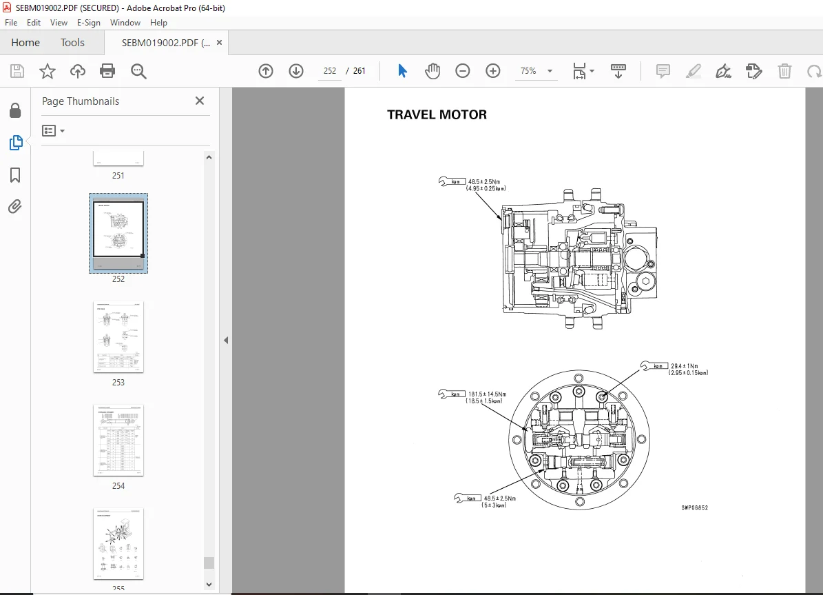
TRAVEL MOTOR 72
VALVE CONTROL . 78
PPC VALVE . 79
PPC LOCK SOLENOID VALVE . 83
TRAVEL 2-SPEED SELECTER VALVE . 85
ELECTRIC WIRING DIAGRAM . 86
MONITOR SYSTEM 88
20 TESTING AND ADJUSTING 91
STANDARD VALUE TABLE FOR ENGINE RELATED PARTS . 92
STANDARD VALUE TABLE FOR CHASSIS RELATED PARTS 93
STANDARD VALUE TABLE FOR ELECTRICAL PARTS .101
TESTING AND ADJUSTING .103
TOOLS FOR TESTING, ADJUSTING, AND TROUBLESHOOTING .104
MEASURING ENGINE SPEED 105
MEASURING EXHAUST COLOR .106
ADJUSTING VALVE CLEARANCE .107
MEASURING COMPRESSION PRESSURE 108
TESTING AND ADJUSTING FUEL INJECTION TIMING .109
MEASURING ENGINE OIL PRESSURE .110
TESTING AND ADJUSTING FAN BELT TENSION 111
ADJUSTING FUEL CONTROL LEVER 112
MEASURING SPROCKET WEAR .113
TESTING AND ADJUSTING TRACK SHOE TENSION 114
TESTING AND ADJUSTING HYDRAULIC PRESSURE IN WORK EQUIPMENT, SWING, TRAVEL CIRCUIT .115
TESTING AND ADJUSTING LS DIFFERENTIAL PRESSURE 117
ADJUSTING PC VALVE SPRING .119
TESTING AND ADJUSTING CONTROL CIRCUIT PRESSURE 120
TESTING PPC LOCK VALVE 121
TESTING PPC VALVE OUTPUT PRESSURE AND SWING HOLDING BRAKE INLET PORT PRESSURE .122
ADJUSTING WORK EQUIPMENT, SWING PPC VALVE .124
TESTING AND ADJUSTING TRAVEL DEVIATION 125
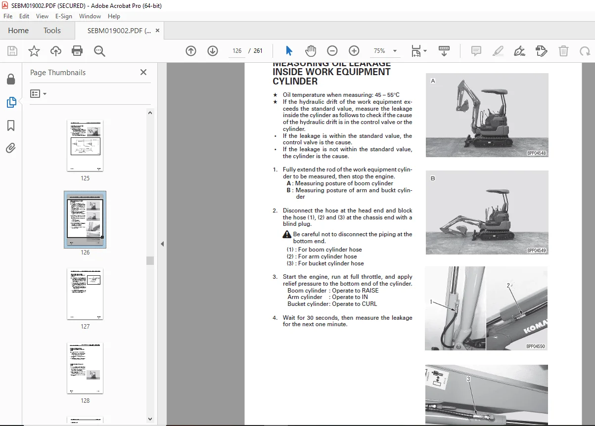
MEASURING OIL LEAKAGE INSIDE WORK EQUIPMENT CYLINDER 126
RELEASING REMAINING PRESSURE FROM HYDRAULIC CIRCUIT .127
RELEASING REMAINING PRESSURE FROM HYDRAULIC TANK 128
PRESSURIZING HYDRAULIC TANK .128
BLEEDING AIR 129
TROUBLESHOOTING .131
POINTS TO REMEMBER WHEN TROUBLESHOOTING .132
SEQUENCE OF EVENTS IN TROUBLESHOOTING .133
POINTS TO REMEMBER WHEN CARRYING OUT MAINTENANCE 134
CHECKS BEFORE TROUBLESHOOTING .142
CONNECTOR TYPES AND MOUNTING LOCATIONS 143
CONNECTOR PIN ALLOCATION DRAWING 144
CONNECTION TABLE FOR CONNECTOR PIN NUMBERS 146
METHOD OF USING TROUBLESHOOTING CHARTS 156
TROUBLESHOOTING OF ELECTRICAL SYSTEM (E MODE) .158
E-MODE RELATED ELECTRICAL CIRCUIT DIAGRAM .159
E-1 ENGINE DOES NOT START .161
a) WHEN STARTING MOTOR DOES NOT TURN (STARTING SYSTEM) 161
b) WHEN STARTING MOTOR TURNS (ENGINE STOP SOLENOID SYSTEM) 163
E-2 ENGINE DOES NOT STOP 165
E-3 WORK EQUIPMENT DOES NOT MOVE EVEN WHEN WORK EQUIPMENT LOCK LEVER IS CANCELED 166
E-4 WORK EQUIPMENT MOVES EVEN WHEN WORK EQUIPMENT LOCK LEVER IS LOCKED 168
E-5 TRAVEL ALARM DOES NOT SOUND .169
TROUBLESHOOTING OF HYDRAULIC, MECHANICAL SYSTEM (H MODE) 170
TABLE OF FAILURE MODES AND CAUSES .171
H-1 SPEEDS OF ALL WORK EQUIPMENT, SWING, TRAVEL ARE SLOW OR LACK POWER 173
H-2 THERE IS EXCESSIVE DROP IN ENGINE SPEED, OR ENGINE STALLS .174
H-3 NO WORK EQUIPMENT, TRAVEL, SWING MOVE .174
H-4 ABNORMAL NOISE GENERATED (FROM AROUND PUMP) .175
H-5 FINE CONTROL ABILITY IS POOR OR RESPONSE IS POOR 175
H-6 BOOM IS SLOW OR LACKS POWER .176
H-7 ARM IS SLOW OR LACKS POWER 176
H-8 BUCKET IS SLOW OR LACKS POWER .177
H-9 BOOM SWING IS SLOW OR LACKS POWER .177
H-10 BLADE IS SLOW OR LACKS POWER .178
H-11 BOOM, ARM, BUCKET DO NOT MOVE (BOOM SWING, BLADE, TRAVEL AND SWING ARE NORMAL) .178
H-12 EXCESSIVE HYDRAULIC DRIFT (BOOM, ARM, BUCKET, BOOM SWING, BLADE) .179
a) BOOM, BUCKET, BOOM SWING, BLADE 179
b) ARM 179
H-13 EXCESSIVE TIME LAG (ENGINE AT LOW IDLING) 179
a) BOOM, ARM 179
b) BUCKET .179
H-14 IN COMPOUND OPERATIONS, WORK EQUIPMENT WITH LARGER LOAD IS SLOW 180
H-15 TRAVEL DEVIATION .181
a) DEVIATION IN NORMAL TRAVEL .181
b) DEVIATION WHEN STARTING 181
H-16 TRAVEL SPEED IS SLOW OR LACKS POWER 182
H-17 STEERING DOES NOT TURN EASILY 182
H-18 TRAVEL SPEED DOES NOT SWITCH .182
H-19 TRAVEL DOES NOT MOVE (ONE SIDE ONLY) .183
H-20 SWING SPEED IS SLOW OR LACKS POWER .183
a) SPEED IS SLOW OR LACKS POWER IN BOTH DIRECTIONS 183
b) SPEED IS SLOW OR LACKS POWER IN ONE DIRECTION ONLY .183
H-21 DOES NOT SWING .184
a) DOES NOT SWING IN EITHER DIRECTION .184
b) DOES NOT SWING IN ONE DIRECTION ONLY .184
H-22 SWING ACCELERATION IS POOR .185
a) ACCELERATION IS POOR IN BOTH DIRECTIONS 185
b) ACCELERATION IS POOR IN ONE DIRECTION ONLY .185
H-23 EXCESSIVE OVERRUN WHEN STOPPING SWING 186
a) OVERRUN WHEN STOPPING IS EXCESSIVE IN BOTH DIRECTIONS 186
b) OVERRUN WHEN STOPPING IS EXCESSIVE IN ONE DIRECTION ONLY .186
H-24 EXCESSIVE SHOCK WHEN STOPPING SWING (IN ONE DIRECTION ONLY) 186
H-25 EXCESSIVE ABNORMAL NOISE WHEN STOPPING SWING .187
H-26 EXCESSIVE HYDRAULIC DRIFT OF SWING .187
TROUBLESHOOTING OF MACHINE MONITOR SYSTEM (M MODE) 188
ELECTRICAL CIRCUIT DIAGRAM FOR M MODE RELATED PARTS .189
M-1 ABNORMALITY IN ENGINE OIL PRESSURE CAUTION LAMP SYSTEM 190
a) LAMP DOES NOT LIGHT UP WHEN STARTING SWITCH IS TURNED ON .190
b) LAMP LIGHTS UP WHEN ENGINE IS RUNNING (ENGINE OIL PRESSURE IS NORMAL) 190
M-2 ABNORMALITY IN CHARGE CAUTION LAMP SYSTEM .192
a) LAMP DOES NOT LIGHT UP WHEN STARTING SWITCH IS TURNED ON .192
b) LAMP LIGHTS UP WHEN ENGINE IS RUNNING (BATTERY CHARGE IS NORMAL) .192
M-3 ABNORMALITY IN ENGINE WATER TEMPERATURE CAUTION LAMP SYSTEM .194
a) LAMP DOES NOT STAY LIGHTED UP FOR 3 SECONDS WHEN STARTING SWITCH IS TURNED ON 194
b) LAMP DOES NOT GO OUT AFTER STARTING SWITCH HAS BEEN AN ON FOR 3 SECONDS 194
c) LAMP LIGHTS UP WHEN ENGINE IS RUNNING (ENGINE WATER TEMPERATURE IS NORMAL) .195
M-4 ABNORMALITY IN PREHEATING PILOT LAMP 196
a) LAMP DOES NOT LIGHT UP WHEN STARTING SWITCH IS TURNED TO HEAT 196
b) LAMP DOES NOT GO OUT WHEN STARTING SWITCH IS AT HEAT AND PREHEATING TIME (APPROX. 18 SEC.) IS COMPLETED 196
c) LAMP LIGHTS UP WHEN STARTING SWITCH IS AT POSITION OTHER THAN HEAT .197
M-5 ABNORMALITY IN FUEL GAUGE SYSTEM 198
a) GAUGE DOES NOT GO UP FROM E WHEN FUEL IS ADDED TO FUEL TANK 198
b) GAUGE DOES NOT GO DOWN FROM F EVEN WHEN THERE IS NO FUEL IN FUEL TANK 198
c) FUEL LEVEL DOES NOT MATCH GAUGE DISPLAY 199
M-6 ABNORMALITY IN SERVICE METER SYSTEM .200
a) SERVICE METER DOES NOT ADVANCE WHEN STARTING SWITCH IS AT ON .200
b) SERVICE METER ADVANCES WHEN STARTING SWITCH IS AT OFF 200
c) PILOT LAMP DOES NOT FLASH WHEN SERVICE METER IS ADVANCING 200
M-7 ABNORMALITY IN NIGHT LIGHTING SYSTEM 202
a) NIGHT LIGHTING DOES NOT LIGHT UP WHEN LAMP SWITCH IS TURNED ON .202
b) NIGHT LIGHTING LIGHTS UP WHEN LAMP SWITCH IS TURNED OFF 202
30 DISASSEMBLY AND ASSEMBLY .204
METHOD OF USING MANUAL 205
PRECAUTIONS WHEN CARRYING OUT OPERATION .206
SPECIAL TOOL LIST .208
ENGINE AND HYDRAULIC PUMP .209
REMOVAL .209
INSTALLATION 213
CENTER SWIVEL JOINT .214
REMOVAL .214
INSTALLATION 214
DISASSEMBLY .215
ASSEMBLY 215
SWING MOTOR .216
REMOVAL .216
INSTALLATION 216
REVOLVING FRAME .217
REMOVAL .217
INSTALLATION 218
SWING CIRCLE 219
REMOVAL .219
INSTALLATION 219
IDLER .220
ASSEMBLY 220
TRACK ROLLER 221
ASSEMBLY 221
RUBBER SHOE .222
REMOVAL .222
INSTALLATION 222
CONTROL VALVE .223
DISASSEMBLY .223
ASSEMBLY 228
HYDRAULIC CYLINDER 235
ASSEMBLY 235
40 MAINTENANCE STANDARD .238
SWING CIRCLE 239
TRACK FRAME, RECOIL SPRING 240
IDLER .241
TRACK ROLLER 242
TRACK SHOE 243
HYDRAULIC PUMP 245
CONTROL VALVE .246
CENTER SWIVEL JOINT .250
SWING MOTOR .251
TRAVEL MOTOR 252
PPC VALVE .253
HYDRAULIC CYLINDER 254
WORK EQUIPMENT 255
90 OTHERS .257
HYDRAULIC CIRCUIT DIAGRAM (VARIABLE GAUGE TYPE) .258
HYDRAULIC CIRCUIT DIAGRAM (FIXED GAUGE TYPE) 259
ELECTRIC CIRCUIT DIAGRAM (SERIAL NO.: 10001-10634) 260
ELECTRIC CIRCUIT DIAGRAM (SERIAL NO.: 10635 AND UP) .261
DESCRIPTION:
Komatsu PC15MR-1 Hydraulic Excavator Shop Manual SEBM019002 – PDF DOWNLOAD
- MACHINE MODEL SERIAL NUMBER
PC15MR-1 10001 and up
Composition of shop manual
This shop manual contains the necessary technical information for services performed in a workshop.
For ease of understanding, the manual is divided into the following sections.
00. Index and foreword
This section explains the shop manuals list, table of contents, safety, and basic information.
01. Specification
This section explains the specifications of the machine.
10. Structure, function and maintenance standard
This section explains the structure, function, and maintenance standard values of each component.
The structure and function sub-section explains the structure and function of each component. It
serves not only to give an understanding of the structure, but also serves as reference material for
troubleshooting. The maintenance standard sub-section explains the criteria and remedies for disassembly
and service.
20. Standard value table
This section explains the standard values for new machine and judgement criteria for testing,
adjusting, and troubleshooting. This standard value table is used to check the standard values in
testing and adjusting and to judge parts in troubleshooting.
30. Testing and adjusting
This section explains measuring instruments and measuring methods for testing and adjusting, and
method of adjusting each part. The standard values and judgement criteria for testing and adjusting
are explained in Testing and adjusting.
40. Troubleshooting
This section explains how to find out failed parts and how to repair them. The troubleshooting is
divided by failure modes. The “S mode” of the troubleshooting related to the engine may be also
explained in the Chassis volume and Engine volume. In this case, see the Chassis volume.
50. Disassembly and assembly
This section explains the special tools and procedures for removing, installing, disassembling, and
assembling each component, as well as precautions for them. In addition, tightening torque and
quantity and weight of coating material, oil, grease, and coolant necessary for the work are also
explained.
90. Diagrams and drawings (chassis volume)/Repair and replacement of parts (engine volume)
q Chassis volume
This section gives hydraulic circuit diagrams and electrical circuit diagrams.
q Engine volume
This section explains the method of reproducing, repairing, and replacing parts.
2. Revision and distribution
Any additions, revisions, or other change of notices will be sent to KOMATSU distributors. Get the most
up-to-date information before you start any work.
G.B 26/12/24



