Komatsu PC160LC-8 Hydraulic Excavator Shop Manual 25001 and up – PDF DOWNLOAD
Original price was: $51.95.$34.95Current price is: $34.95.
Komatsu PC160LC-8 Hydraulic Excavator Shop Manual
Book Code: SEN04566-10
SERIAL NUMBERS : 25001 and up
Description
Komatsu PC160LC-8 Hydraulic Excavator Shop Manual
FILE DETAILS:
Komatsu PC160LC-8 Hydraulic Excavator Shop Manual
Brands: Komatsu
Equipment Type: Hydraulic Excavator
Manuals Type: Shop Manual
Machine Model: PC160LC-8
Serial Number: 25001 and up
Book Code: SEN04566-10
Language: English
Pages: 1016
File Format: Portable Document Format (PDF)
DESCRIPTION:
Komatsu PC160LC-8 Hydraulic Excavator Shop Manual
How to read the shop manual:
1. Composition of shop manual:
This shop manual contains the necessary technical information for services performed in a workshop. For ease of understanding, the manual is divided into the following sections.
00. Index and foreword:
This section explains the shop manuals list, table of contents, safety, and basic information.
01. Specification:
This section explains the specifications of the machine.
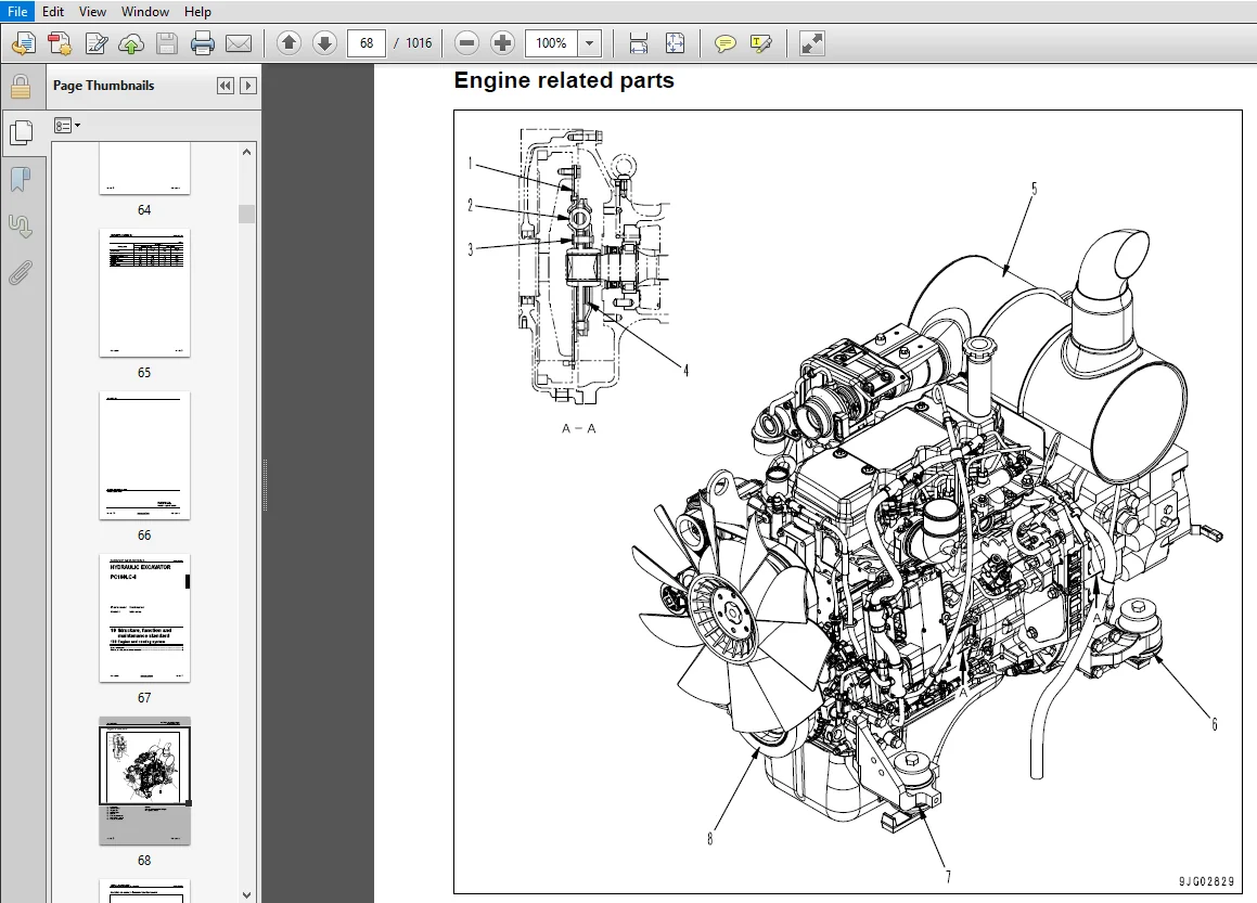
10. Structure, function and maintenance standard:
This section explains the structure, function, and maintenance standard values of each component. The structure and function sub-section explains the structure and function of each component. It serves not only to give an understanding of the structure, but also serves as reference material for troubleshooting. The maintenance standard sub-section explains the criteria and remedies for disassembly and service.
20. Standard value table:
This section explains the standard values for new machine and judgement criteria for testing, adjusting, and troubleshooting. This standard value table is used to check the standard values in testing and adjusting and to judge parts in troubleshooting.
30. Testing and adjusting:
This section explains measuring instruments and measuring methods for testing and adjusting, and method of adjusting each part. The standard values and judgement criteria for testing and adjusting are explained in Testing and adjusting.
40. Troubleshooting:
This section explains how to find out failed parts and how to repair them. The troubleshooting is divided by failure modes. The “S mode” of the troubleshooting related to the engine may be also explained in the Chassis volume and Engine volume. In this case, see the Chassis volume.
50. Disassembly and assembly:
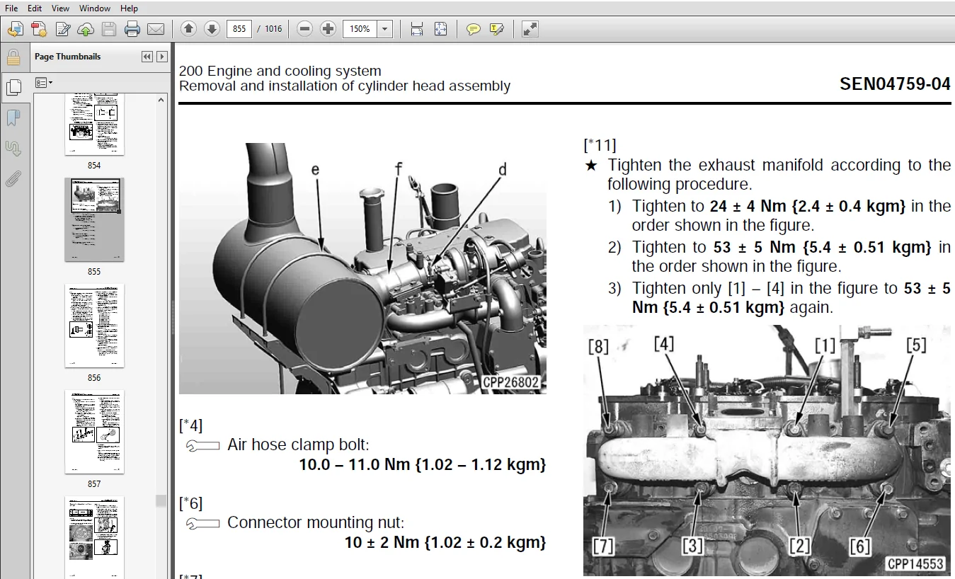
This section explains the special tools and procedures for removing, installing, disassembling, and assembling each component, as well as precautions for them. In addition, tightening torque and quantity and weight of coating material, oil, grease, and coolant necessary for the work are also explained.
90. Diagrams and drawings (chassis volume)/Repair and replacement of parts (engine volume):
- Chassis volume
This section gives hydraulic circuit diagrams and electrical circuit diagrams. - Engine volume
This section explains the method of reproducing, repairing, and replacing parts.
TABLE OF CONTENTS:
Komatsu PC160LC-8 Hydraulic Excavator Shop Manual
COVER
............................................................................................................   1
00 Index and foreword.............................................................................................   0
	100 Index.....................................................................................................   3
		Composition of shop manual................................................................................   4
		Table of contents.........................................................................................   6
	200 Foreword and general information..........................................................................  15
		Safety notice.............................................................................................  16
		How to read the shop manual...............................................................................  21
		Explanation of terms for maintenance standard.............................................................  23
		Handling of electric equipment and hydraulic component....................................................  25
		Handling of connectors newly used for engines.............................................................  34
		How to read electric wire code............................................................................  37
		Precautions when carrying out operation...................................................................  40
		Method of disassembling and connecting push-pull type coupler.............................................  43
		Standard tightening torque table..........................................................................  46
		Conversion table..........................................................................................  50
01 Specification..................................................................................................   0
	100 Specification and technical data..........................................................................  57
		Specification dimension drawings..........................................................................  58
		Specifications............................................................................................  60
		Weight table..............................................................................................  62
		Table of fuel, coolant and lubricants.....................................................................  64
10 Structure, function and maintenance standard...................................................................   0
	100 Engine and cooling system.................................................................................  67
		Engine related parts......................................................................................  68
		Radiator, oil cooler, aftercooler and fuel cooler.........................................................  69
	200 Power train system........................................................................................  71
		Power train...............................................................................................  72
		Swing circle..............................................................................................  73
		Swing machinery...........................................................................................  74
		Final drive...............................................................................................  76
		Sprocket..................................................................................................  78
	300 Undercarriage and frame...................................................................................  81
		Track frame, recoil spring................................................................................  82
		Idler.....................................................................................................  84
		Carrier roller............................................................................................  86
		Track roller..............................................................................................  87
		Track shoe................................................................................................  88
	401 Hydraulic system, Part 1..................................................................................  93
		Hydraulic equipment layout drawing........................................................................  94
		Hydraulic tank............................................................................................  96
		Hydraulic pump............................................................................................  98
	402 Hydraulic system, Part 2.................................................................................. 125
		Control valve............................................................................................. 126
		CLSS...................................................................................................... 140
		Functions and operation by valve.......................................................................... 144
	403 Hydraulic system, Part 3.................................................................................. 181
		Valve control............................................................................................. 182
		PPC valve................................................................................................. 183
		Solenoid valve............................................................................................ 204
		Accumulator............................................................................................... 206
		Return oil filter......................................................................................... 207
		Center swivel joint....................................................................................... 208
		Travel motor.............................................................................................. 209
		Swing motor............................................................................................... 219
		Attachment circuit selector valve......................................................................... 220
		Hydraulic cylinder........................................................................................ 224
	500 Work equipment............................................................................................ 227
		Work equipment............................................................................................ 228
		Dimensions of components.................................................................................. 230
	600 Cab and its attachments................................................................................... 235
		Air conditioner piping.................................................................................... 236
	700 Electrical system......................................................................................... 239
		Engine control system..................................................................................... 240
		Electronic control system................................................................................. 250
		Monitor system............................................................................................ 278
		Sensor.................................................................................................... 304
		KOMTRAX system............................................................................................ 308
20 Standard value table...........................................................................................   0
	100 Standard service value table.............................................................................. 311
		Standard value table for engine........................................................................... 312
		Standard value table for chassis related parts............................................................ 313
30 Testing and adjusting..........................................................................................   0
	101 Testing and adjusting, Part 1............................................................................. 325
		Tools for testing, adjusting and troubleshooting.......................................................... 327
		Testing engine speed...................................................................................... 330
		Testing intake air pressure (boost pressure).............................................................. 331
		Testing exhaust gas color................................................................................. 332
		Adjusting valve clearance................................................................................. 333
		Testing compression pressure.............................................................................. 335
		Testing blow-by pressure.................................................................................. 337
		Testing engine oil pressure............................................................................... 338
		Handling fuel system parts................................................................................ 339
		Releasing residual pressure from fuel system.............................................................. 339
		Testing fuel pressure..................................................................................... 340
		Measuring fuel discharge, return and leakage.............................................................. 342
		Bleeding air from fuel circuit............................................................................ 346
		Checking fuel circuit for leakage......................................................................... 348
		Checking and adjusting air conditioner compressor belt tension............................................ 349
		Replacing fan belt........................................................................................ 350
		Testing clearance in swing circle bearings................................................................ 351
		Testing and adjusting track shoe tension.................................................................. 352
		Inspection and adjustment oil pressure in work equipment, swing, and travel circuits...................... 353
		Testing control circuit basic pressure.................................................................... 356
		Testing and adjusting pump PC control circuit oil pressure................................................ 357
		Testing and adjusting pump LS control circuit oil pressure................................................ 360
		Testing solenoid valve output pressure.................................................................... 364
		Testing PPC valve output pressure......................................................................... 367
		Adjusting play of work equipment and swing PPC valves..................................................... 368
		Inspecting locations of hydraulic drift of work equipment................................................. 369
		Testing and adjusting travel deviation.................................................................... 371
		Releasing remaining pressure in hydraulic circuit......................................................... 373
		Measurement of oil leakage................................................................................ 374
		Bleeding air from various parts........................................................................... 376
		Inspection procedures for diode........................................................................... 378
		Checking cab tipping stopper.............................................................................. 379
		Installation and adjustment of mirrors and camera......................................................... 380
		Inspection of air conditioner Recirc/Fresh air filter..................................................... 384
	102 Testing and adjusting, Part 2............................................................................. 387
		Special functions of machine monitor...................................................................... 388
	103 Testing and adjusting, Part 3............................................................................. 441
		Handling voltage circuit of engine controller............................................................. 442
		Preparation work for troubleshooting of electrical system................................................. 443
		Procedure for testing diodes.............................................................................. 448
		Pm-clinic service......................................................................................... 449
40 Troubleshooting................................................................................................   0
	100 Failure code table and fuse locations..................................................................... 455
		Failure code table........................................................................................ 456
		Fuse locations............................................................................................ 459
	200 General information on troubleshooting.................................................................... 463
		Points to remember when troubleshooting................................................................... 464
		Sequence of events in troubleshooting..................................................................... 465
		Checks before troubleshooting............................................................................. 466
		Classification and troubleshooting steps.................................................................. 467
		Information in troubleshooting table...................................................................... 468
		Phenomena looking like troubles and troubleshooting Nos................................................... 470
		Connection table for connector pin numbers................................................................ 473
		T- branch box and T- branch adapter table................................................................. 509
	301 Troubleshooting by failure code, Part 1................................................................... 513
		Failure code [989L00] Engine controller lock caution 1.................................................... 515
		Failure code [989M00] Engine controller lock caution 2.................................................... 515
		Failure code [989N00] Engine controller lock caution 3.................................................... 516
		Failure code [AA10NX] Air cleaner clogging................................................................ 517
		Failure code [AB00KE] Charge voltage low.................................................................. 518
		Failure code [B@BAZG] Eng oil press. low.................................................................. 520
		Failure code [B@BAZK] Eng oil level low................................................................... 521
		Failure code [B@BCNS] Eng coolant overheat................................................................ 522
		Failure code [B@BCZK] Eng water level low................................................................. 524
		Failure code [B@HANS] Hydr oil overheat................................................................... 526
		Failure code [CA111] ECM critical internal failure........................................................ 528
		Failure code [CA115] Eng Ne and bkup speed sens error..................................................... 529
		Failure code [CA122] Chg air press sensor high error...................................................... 530
		Failure code [CA123] Chg air press sensor low error....................................................... 532
		Failure code [CA131] Throttle sensor high error........................................................... 534
		Failure code [CA132] Throttle sensor low error............................................................ 536
		Failure code [CA144] Coolant temp sens high error......................................................... 538
		Failure code [CA145] Coolant temp sens low error.......................................................... 540
		Failure code [CA153] Chg air temp sensor high error....................................................... 542
		Failure code [CA154] Chg air temp sensor low error........................................................ 544
		Failure code [CA155] Chg air temp high speed derate....................................................... 546
		Failure code [CA187] Sens supply 2 volt low error......................................................... 548
		Failure code [CA221] Ambient press sens high error........................................................ 550
		Failure code [CA222] Ambient press sens low error......................................................... 552
		Failure code [CA227] Sens supply 2 volt high error........................................................ 554
		Failure code [CA234] Eng. overspeed....................................................................... 555
		Failure code [CA238] Ne speed sens supply volt error...................................................... 556
		Failure code [CA271] IMV/PCV1 short error................................................................. 557
		Failure code [CA272] IMV/PCV1 open error.................................................................. 558
		Failure code [CA322] Inj #1 open/short error.............................................................. 560
		Failure code [CA324] Inj #3 open/short error.............................................................. 562
		Failure code [CA331] Inj #2 open/short error.............................................................. 564
		Failure code [CA332] Inj #4 open/short error.............................................................. 566
	302 Troubleshooting by failure code, Part 2................................................................... 569
		Failure code [CA342] Calibration code incompatibility..................................................... 571
		Failure code [CA351] Injectors Drive Circuit Error........................................................ 572
		Failure code [CA352] Sens supply 1 volt low error......................................................... 574
		Failure code [CA386] Sens supply 1 volt high error........................................................ 576
		Failure code [CA428] Water in fuel sensor high error...................................................... 578
		Failure code [CA429] Water in fuel sensor low error....................................................... 580
		Failure code [CA435] Eng oil press sw error............................................................... 582
		Failure code [CA441] Battery voltage low error............................................................ 584
		Failure code [CA442] Battery voltage high error........................................................... 586
		Failure code [CA449] Rail press very high error........................................................... 588
		Failure code [CA451] Rail press sensor high error......................................................... 590
		Failure code [CA452] Rail press sensor low error.......................................................... 592
		Failure code [CA488] Chg air temp high torque derate...................................................... 594
		Failure code [CA553] Rail press high error................................................................ 594
		Failure code [CA559] Rail press low error................................................................. 595
		Failure code [CA689] Eng Ne speed sensor error............................................................ 596
		Failure code [CA731] Eng Bkup speed sens phase error...................................................... 598
		Failure code [CA757]  All persistent data lost error...................................................... 600
		Failure code [CA778] Eng Bkup speed sensor error.......................................................... 602
		Failure code [CA1633] KOMNET datalink timeout error....................................................... 604
		Failure code [CA2185] Throttle sens. sup. volt. high error................................................ 606
		Failure code [CA2186] Throttle sens. sup. volt. low error................................................. 607
		Failure code [CA2249] Rail press very low error........................................................... 608
		Failure code [CA2311] IMV solenoid error.................................................................. 610
		Failure code [CA2555] Grid htr relay volt high error...................................................... 612
		Failure code [CA2556] Grid htr relay volt low error....................................................... 614
		Failure code [D110KB] Battery relay drive short........................................................... 616
		Failure code [D19JKZ] Personal code relay abnormality..................................................... 618
		Failure code [D862KA] GPS antenna discon.................................................................. 620
		Failure code [DA22KK] Pump solenoid power low error....................................................... 622
		Failure code [DA25KP] 5V sensor 1 power abnormality....................................................... 624
		Failure code [DA26KP] 5V sensor 2 power abnormality....................................................... 627
		Failure code [DA29KQ] Model selection abnormality......................................................... 628
	303 Troubleshooting by failure code, Part 3................................................................... 631
		Failure code [DA2RMC] CAN discon (Pump controller detected)............................................... 634
		Failure code [DAF8KB] Short circuit in camera power supply................................................ 636
		Failure code [DAFGMC] GPS module error.................................................................... 638
		Failure code [DAFRMC] CAN discon (Monitor detected)....................................................... 640
		Failure code [DGH2KB] Hydr oil sensor short............................................................... 642
		Failure code [DHPAMA] F Pump press sensor abnormality..................................................... 644
		Failure code [DHPBMA] R Pump press sensor abnormality..................................................... 646
		Failure code [DHS5KX] Travel PPC press sensor abnormality................................................. 648
		Failure code [DHSAMA] Sw RH PPC press sen. abnormality.................................................... 650
		Failure code [DHSBMA] Sw LH PPC press sen. abnormality.................................................... 652
		Failure code [DHX1MA] Overload sensor abnormality (Analog)................................................ 654
		Failure code [DW43KA] Travel speed sol discon............................................................. 655
		Failure code [DW43KB] Travel speed sol short.............................................................. 656
		Failure code [DW45KA] Swing brake sol discon.............................................................. 658
		Failure code [DW45KB] Swing brake sol short............................................................... 660
		Failure code [DW91KA] Travel junction sol discon.......................................................... 662
		Failure code [DW91KB] Travel junction sol short........................................................... 664
		Failure code [DWA2KA] Service sol discon.................................................................. 666
		Failure code [DWA2KB] Service sol short................................................................... 667
		Failure code [DWJ0KA] Merge-divider sol discon............................................................ 668
		Failure code [DWJ0KB] Merge-divider sol short............................................................. 670
		Failure code [DWK0KA] 2-stage relief sol discon........................................................... 672
		Failure code [DWK0KB] 2-stage relief sol short............................................................ 674
	304 Troubleshooting by failure code, Part 4................................................................... 677
		Failure code [DXA8KA] PC-EPC sol discon................................................................... 678
		Failure code [DXA8KB] PC-EPC sol short.................................................................... 680
		Failure code [DXE4KA] Service current EPC discon.......................................................... 682
		Failure code [DXE4KB] Service current EPC short........................................................... 684
		Failure code [DY20KA] Wiper working abnormality........................................................... 686
		Failure code [DY20MA] Wiper parking abnormality........................................................... 688
		Failure code [DY2CKA] Washer drive discon................................................................. 690
		Failure code [DY2CKB] Washer drive short.................................................................. 692
		Failure code [DY2DKB] Wiper drive (for) short............................................................. 694
		Failure code [DY2EKB] Wiper drive (rev) short............................................................. 696
	400 Troubleshooting of electrical system (E-mode)............................................................. 699
		Before carrying out troubleshooting of electrical system.................................................. 701
		Information in troubleshooting table...................................................................... 703
		E-1 When starting switch turned ON, machine monitor displays nothing...................................... 704
		E-2 When starting switch is turned to ON position (before starting engine), basic check item lights up.... 706
		E-3 Engine does not start (Engine does not crank)......................................................... 709
		E-4 Preheater does not operate............................................................................ 712
		E-5 Automatic warm-up system does not operate (in cold season)............................................ 714
		E-6 All work equipment, swing, and travel mechanism do not move or cannot be locked....................... 716
		E-7 Precaution lights up while engine is running.......................................................... 718
		E-8 Emergency stop item lights up while engine is running................................................. 722
		E-9 Engine coolant temperature gauge does not indicate normally........................................... 723
		E-10 Hydraulic oil temperature gauge does not indicate normally........................................... 724
		E-11 Fuel level gauge does not indicate normally.......................................................... 726
		E-12 Contents of display by machine monitor are different from applicable machine......................... 728
		E-13 Machine monitor does not display some items.......................................................... 728
		E-14 Function switch does not work........................................................................ 728
		E-15 Auto-decelerator does not operate normally........................................................... 729
		E-16 Working mode does not change......................................................................... 730
		E-17 Travel speed does not change......................................................................... 731
		E-18 Alarm buzzer cannot be stopped....................................................................... 732
		E-19 Windshield wiper and window washer do not operate.................................................... 733
		E-20 Power maximizing function does not operate normally.................................................. 735
		E-21 Swing holding brake does not operate normally........................................................ 737
		E-22 Travel alarm does not sound or does not stop sounding................................................ 739
		E-23 Air conditioner does not operate normally (including air conditioner abnormality record)............. 741
		E-24 While starting switch is in OFF position, service meter is not displayed............................. 752
		E-25 Machine monitor cannot be set in service mode........................................................ 752
		E-26 Monitoring function does not display lever control signal normally................................... 754
		E-27 KOMTRAX system does not operate normally............................................................. 764
	500 Troubleshooting of hydraulic and mechanical system (H-mode)............................................... 767
		Information contained in troubleshooting table............................................................ 769
		System chart for hydraulic and mechanical systems......................................................... 770
		H-1 Speed or power of all work equipment, swing, and travel are low....................................... 772
		H-2 Engine speed sharply drops or engine stalls........................................................... 773
		H-3 No work equipment, travel and swing move.............................................................. 774
		H-4 Abnormal noise is heard from around hydraulic pump.................................................... 774
		H-5 Auto-decelerator does not work........................................................................ 775
		H-6 Fine control mode does not function................................................................... 775
		H-7 Speed or power of boom is low......................................................................... 776
		H-8 Speed or power of arm is low.......................................................................... 777
		H-9 Speed or power of bucket is low....................................................................... 778
		H-10 Work equipment does not move in its single operation................................................. 779
		H-11 Hydraulic drift of work equipment is large........................................................... 780
		H-12 Time lag of work equipment is large.................................................................. 781
		H-13 One-touch power max system does not operate.......................................................... 781
		H-14 Work equipment loaded more is slower during compound operation....................................... 782
		H-15 Boom RAISE speed is low in compound operation of swing + boom RAISE.................................. 782
		H-16 Travel speed lowers largely during compound operation of work equipment/swing + travel............... 783
		H-17 Machine deviates during travel....................................................................... 784
		H-18 Travel speed is low.................................................................................. 785
		H-19 Machine cannot be steered easily or steering power is low............................................ 786
		H-20 Travel speed does not change or it is kept low or high............................................... 787
		H-21 Track does not move (Only either side)............................................................... 787
		H-22 Machine does not swing............................................................................... 788
		H-23 Swing acceleration or swing speed is low............................................................. 789
		H-24 Excessive overrun when stopping swing................................................................ 790
		H-25 When upper structure stops swinging, it makes large shock............................................ 791
		H-26 When upper structure stops swinging, it makes large sound............................................ 791
		H-27 Hydraulic drift of swing is large.................................................................... 792
		H-28 Attachment circuit does not change................................................................... 793
		H-29 Flow rate in attachment circuit cannot be adjusted................................................... 793
	600 Troubleshooting of engine (S-mode)........................................................................ 795
		Method of using troubleshooting chart..................................................................... 798
		S-1  Starting performance is poor......................................................................... 802
		S-2  Engine does not start................................................................................ 803
		S-3  Engine does not pick up smoothly..................................................................... 806
		S-4  Engine stops during operations....................................................................... 807
		S-5  Engine does not rotate smoothly...................................................................... 808
		S-6  Engine lack output (or lacks power).................................................................. 809
		S-7  Exhaust smoke is black (incomplete combustion)....................................................... 810
		S-8  Oil consumption is excessive (or exhaust smoke is blue).............................................. 811
		S-9  Oil becomes contaminated quickly..................................................................... 812
		S-10  Fuel consumption is excessive....................................................................... 813
		S-11  Oil is in coolant (or coolant spurts back or coolant level goes down)............................... 814
		S-12  Oil pressure drops.................................................................................. 815
		S-13  Oil level rises (Entry of coolant/fuel)............................................................. 816
		S-14  Coolant temperature becomes too high (overheating).................................................. 817
		S-15  Abnormal noise is made.............................................................................. 818
		S-16  Vibration is excessive.............................................................................. 819
50 Disassembly and assembly.......................................................................................   0
	100 General information on disassembly and assembly........................................................... 821
		How to read this manual................................................................................... 822
		Coating materials list.................................................................................... 824
		Special tool list......................................................................................... 827
		Sketches of special tools................................................................................. 830
	200 Engine and cooling system................................................................................. 833
		Removal and installation of fuel supply pump assembly..................................................... 834
		Removal and installation of fuel injector assembly........................................................ 838
		Removal and installation of cylinder head assembly........................................................ 845
		Removal and installation of front oil seal................................................................ 858
		Removal and installation of rear oil seal................................................................. 860
		Removal and installation of radiator assembly............................................................. 863
		Removal and installation of aftercooler assembly.......................................................... 865
		Removal and installation of hydraulic oil cooler assembly................................................. 867
		Removal and installation of engine and hydraulic pump assembly............................................ 869
		Removal and installation of engine hood assembly.......................................................... 877
		Removal and installation of fuel tank assembly............................................................ 879
	300 Power train............................................................................................... 883
		Removal and installation of travel motor and final drive assembly......................................... 884
		Disassembly and assembly of final drive assembly.......................................................... 886
		Removal and installation of swing motor and swing machinery assembly...................................... 893
		Disassembly and assembly of swing motor and swing machinery assembly...................................... 895
		Removal and installation of swing circle assembly......................................................... 902
	400 Undercarriage and frame................................................................................... 905
		Disassembly and assembly of carrier roller................................................................ 906
		Disassembly and assembly of track roller assembly......................................................... 909
		Disassembly and assembly of idler assembly................................................................ 911
		Disassembly and assembly of recoil spring................................................................. 914
		Expansion and installation of track shoe assembly......................................................... 916
		Removal and installation of sprocket...................................................................... 918
		Removal and installation of revolving frame assembly...................................................... 919
		Removal and installation of counterweight assembly........................................................ 921
	500 Hydraulic system.......................................................................................... 925
		Removal and installation of center swivel joint assembly.................................................. 926
		Disassembly and assembly of center swivel joint assembly.................................................. 928
		Removal and installation of hydraulic tank assembly....................................................... 930
		Removal and installation of hydraulic pump assembly....................................................... 933
		Removal and installation of hydraulic pump input shaft oil seal........................................... 936
		Removal and installation of control valve assembly........................................................ 937
		Disassembly and assembly of control valve assembly........................................................ 941
		Disassembly and assembly of work equipment PPC valve assembly............................................. 943
		Disassembly and assembly of travel PPC valve assembly..................................................... 944
		Disassembly and assembly of hydraulic cylinder assembly................................................... 947
	600 Work equipment Body....................................................................................... 955
		Removal and installation of work equipment assembly....................................................... 956
	700 Cab and its attachments................................................................................... 961
		Removal and installation of operator’s cab assembly....................................................... 962
		Removal and installation of operator cab glass (stuck glass).............................................. 966
		Removal and installation of front window assembly......................................................... 976
		Removal and installation of floor frame assembly.......................................................... 983
		Removal and installation of air conditioner unit assembly................................................. 987
	800 Electrical system......................................................................................... 991
		Removal and installation of monitor assembly.............................................................. 992
		Removal and installation of pump controller assembly...................................................... 994
		Removal and installation of engine controller assembly.................................................... 997
		Removal and installation of KOMTRAX terminal.............................................................. 999
90 Diagrams and drawings..........................................................................................   0
	100 Hydraulic circuit diagram.................................................................................1001
		Hydraulic circuit diagram.................................................................................1003
	200 Electrical diagrams and drawings..........................................................................1006
		Electrical circuit diagram (1/6)..........................................................................1008
		Electrical circuit diagram (2/6)..........................................................................1009
		Electrical circuit diagram (3/6)..........................................................................1010
		Electrical circuit diagram (4/6)..........................................................................1011
		Electrical circuit diagram (5/6)..........................................................................1012
		Electrical circuit diagram (6/6)..........................................................................1013
		Connectors table and arrangement drawing..................................................................1014
KOMATSU PC160LC-8 HYDRAULIC EXCAVATOR SHOP MANUAL 25001 AND UP – PDF DOWNLOAD:
IMAGES PREVIEW OF THE MANUAL:
PLEASE NOTE:
- This is the same manual used by the dealers to diagnose and troubleshoot your vehicle
- You will be directed to the download page as soon as the purchase is completed. The whole payment and downloading process will take anywhere between 2-5 minutes
- Need any other service / repair / parts manual, please feel free to contact [email protected] . We still have 50,000 manuals unlisted


