Komatsu PC170LC-10 Hydraulic Excavator Shop Manual UENBM00420 PDF
$39.95
Komatsu PC170LC-10 Hydraulic Excavator Shop Manual UENBM00420 – PDF DOWNLOAD
Description
Komatsu PC170LC-10 Hydraulic Excavator Shop Manual UENBM00420 – PDF DOWNLOAD
FILE DETAILS:
Komatsu PC170LC-10 Hydraulic Excavator Shop Manual UENBM00420 – PDF DOWNLOAD
Language : English
Pages : 1452
Downloadable : Yes
File Type : PDF
TABLE OF CONTENTS:
Komatsu PC170LC-10 Hydraulic Excavator Shop Manual UENBM00420 – PDF DOWNLOAD
Table of contents 4
Foreword, safety and general information 16
Important safety notice 16
Fire prevention 21
Dispose of waste materials 22
How to read the shop manual 23
Explanation of terms for maintenance standard 25
Handling equipment of fuel system devices 27
Handling of intake system parts 28
Handling of hydraulic equipment 29
Method of disconnecting and connecting of push-pull type coupler 31
Type 1 31
Type 2 32
Type 3 33
Handling of electrical equipment 34
How to read electric wire code 42
Precautions when performing operation 45
Practical use of KOMTRAX 50
Standard tightening torque table 51
List of abbreviation 57
Conversion table 62
Table of contents 68
Specifications 69
Specification drawing 69
PC170LC-10 69
Working range drawings 70
PC170LC-10 70
Specifications 71
PC170LC-10 71
Weight table 74
Table of fuel, coolant, and lubricants 75
10 Structure and function 77
Contents 78
Engine and cooling system 79
Engine related parts 79
Specifications 80
Variable flow turbocharger 81
Specifications 83
Operation 84
EGR system piping drawing 85
Function 85
EGR system circuit diagram 87
Operation 87
EGR valve 88
Structure 88
Operation 89
EGR cooler 90
Operation 91
KCCV layout drawing 92
Operation 93
KCCV ventilator 95
Function 95
Operation 96
CDR valve 96
KDOC muffler 97
Structure 97
Function 98
Cooling system 99
Specifications 100
Power train 101
Power train system 101
Swing circle 103
Specifications 103
Swing machinery 104
Specifications 105
Final drive 106
Specifications 107
Undercarriage and frame 108
Track frame and idler cushion 108
Specifications 109
Hydraulic system 110
Hydraulic component layout 110
Valve control 113
Hydraulic tank 114
Specifications 114
Oil filler cap 115
CLSS 116
Structure of CLSS 116
Features 116
Configuration 116
Basic principle 117
Main pump 120
LS valve 128
PC valve 133
PC-EPC valve 142
Control valve 147
7-spool valve 147
8-spool valve 160
8-spool valve 163
Unload valve 164
Introduction of LS pressure 169
LS bypass plug 171
Pressure compensation valve 174
Boom regeneration circuit 178
Arm regeneration circuit 180
Merge-divider valve 182
LS separation valve 184
Travel junction valve 186
Boom hydraulic drift prevention valve 188
Main relief valve 191
Back pressure check valve 193
Oil cooler bypass valve 194
2-stage suction-safety valve 195
Swing motor 197
Travel motor 199
Specifications 201
Operation of travel motor 202
Parking brake operation 204
Brake valve 206
PPC valve 214
Work equipment and swing PPC valve 214
Travel PPC valve 221
1st-line attachment PPC valve (with EPC valve) 227
EPC valve 229
2nd-line attachment PPC valve 234
Solenoid valve 236
Attachment circuit selector valve (for high pressure circuit) 239
Function 239
Operation 239
Attachment circuit selector valve (for low pressure circuit) 241
Center swivel joint 244
Accumulator 246
PPC accumulator 246
Work equipment 247
Work equipment 247
Work equipment shim 248
Bucket play adjustment shim 249
Cab and its attachments 250
Cab mount and cab tipping stopper 250
Structure 250
ROPS cab 251
Electrical system 252
Electrical control system 252
General system drawing 252
Engine control function 254
Engine and pump combined control function 256
Control method in each mode 258
Pump and valve control function 262
2-stage relief function 264
One-touch power maximizing function 264
Auto-deceleration function 266
Engine automatic warm-up function 268
Overheat prevention function 270
Turbocharger protection function 271
Swing control function 272
Travel control function 275
PPC lock function 278
System operating lamp function 279
Oil flow adjuster function for attachment 280
System component parts 282
Pump controller 287
Input and output signals of pump controller 288
Fuel control dial 291
Resister for PC-EPC valve 292
CAN terminating resistor 293
Engine oil pressure switch 293
PPC oil pressure switch 294
Machine monitor system 295
Machine monitor 297
KOMTRAX system 316
KOMTRAX terminal 317
Sensor 319
Ambient pressure sensor 319
Charge (boost) pressure and temperature sensor 320
Coolant temperature sensor 321
Ne (crankshaft) speed sensor 321
Bkup (camshaft) speed sensor 322
Common rail pressure sensor 322
Exhaust manifold pressure sensor 323
EGR orifice temperature sensor 323
Variable flow turbocharger motor (with built-in position sensor) 324
EGR valve (with built-in position sensor) 325
Mass air flow and temperature sensor 326
Crankcase pressure sensor 326
Engine oil level sensor 327
Fuel level sensor 328
Coolant level sensor 329
Hydraulic oil temperature sensor 330
Front pump oil pressure sensor 330
Rear pump oil pressure sensor 331
PPC oil pressure sensor 332
Air cleaner clogging sensor 333
Pump swash plate sensor 333
Water-in-fuel sensor 334
20 Standard value tables 335
Contents 336
Standard service value table 337
Standard value table for engine 337
Standard value table for machine 339
Engine speed 339
Control valve spool stroke 339
Travel of control lever 340
Operating effort of control lever and pedal 340
Hydraulic pressure 341
Swing 344
Traveling 345
Work equipment 346
Performance of combined operation 349
Pump swash plate sensor 349
Characteristics of PC flow control 350
Hydraulic pump 350
Machine posture and procedure for measuring performance 351
Standard value table for electrical system 356
Controller 356
Engine control 357
Machine control 360
Machine monitor 362
30 Testing and adjusting 363
Contents 364
Related information on testing and adjusting 365
Tools for testing and adjusting 365
Sketch of tools for testing and adjusting 368
Q2: Sensor adapter 368
-: Socket 368
Engine and cooling system 369
Testing engine speed 369
Testing 369
Testing boost pressure 370
Testing 370
How to fully open engine hood 371
Testing exhaust gas color 372
Testing 372
Testing and adjusting valve clearance 373
Adjusting 374
Testing compression pressure 376
Testing 376
Testing blowby pressure 380
Testing 380
Testing engine oil pressure 381
Testing 381
Testing fuel pressure 382
Testing 384
Testing fuel discharge, return and leakage 387
Testing 388
Bleeding air from fuel system 392
Bleeding air 392
Testing fuel circuit for leakage 394
Testing 394
Handling cylinder cutout mode operation 395
Handling no-injection cranking operation 396
Checking and adjusting air conditioner compressor belt tension 397
Testing 397
Replacing fan belt 398
Replace 398
Power train 399
Testing swing circle bearing clearance 399
Testing 399
Undercarriage and frame 400
Testing and adjusting track tension 400
Testing 400
Hydraulic system 401
Releasing remaining pressure from hydraulic circuit 401
Releasing remaining pressure 401
Testing oil pressure of control circuit 402
Testing 402
Testing and adjusting oil pressure in work equipment, swing, and travel circuits 403
Testing 403
Adjusting 405
Testing and adjusting oil pressure in pump PC control circuit 407
Testing 407
Adjusting 408
Testing and adjusting oil pressure in pump LS control circuit 410
Testing 410
Adjusting 413
Testing outlet pressure of solenoid valve 414
Testing 414
Operating condition 415
Testing PPC valve outlet pressure 417
Testing 417
Adjusting play of work equipment and swing PPC valves 419
Adjusting 419
Testing pump swash plate sensor 420
Testing 420
Isolating the parts causing hydraulic drift in work equipment 421
Testing 421
Testing and adjusting travel deviation 423
Testing 423
Adjusting 423
Testing oil leakage 425
Testing 425
Bleeding air from hydraulic circuit 428
Bleeding air 428
Cab and its attachments 430
Checking cab tipping stopper 430
Testing 430
Adjusting mirrors 431
Electrical system 433
Special functions of machine monitor 433
Ordinary functions and special functions of machine monitor 435
KOMTRAX terminal start-up procedure 491
Adjusting rearview camera angle 494
Adjusting 494
Handling voltage circuit of engine controller 496
Handling battery disconnect switch 497
Testing diodes 498
Testing 498
Pm Clinic 499
Pm Clinic service 499
Check sheet 501
40 Troubleshooting 509
Table of contents 510
Related information on troubleshooting 516
Troubleshooting points 516
Sequence of events in troubleshooting 518
Checks before troubleshooting 520
Inspection procedure before troubleshooting 522
Walk-around check 522
Testing in accordance with testing procedure 523
Preparation work for troubleshooting of electrical system 540
Preparation 540
Classification and procedure for troubleshooting 545
Procedure for troubleshooting 545
Symptom and troubleshooting numbers 548
Information in troubleshooting table 551
Procedure for troubleshooting wiring harness of pressure sensor system for open circuit 553
Connector list and layout 556
Layout of connectors (1/6) 562
Layout of connectors (2/6) 563
Layout of connectors (3/6) 564
Layout of connectors (4/6) 565
Layout of connectors (5/6) 566
Layout of connectors (6/6) 567
Connector contact identification 568
T-branch box and T-branch adapter table 606
Fuse location table 611
Connection table of fuse box 611
Locations of fusible links 612
Locations of fuse boxes and fuse No 612
Failure codes table 613
Troubleshooting by failure code (Display of code) 620
Failure code [879AKA] A/C Inner Sensor Open Circuit 620
Failure code [879AKB] A/C Inner Sensor Short Circuit 621
Failure code [879BKA] A/C Outer Sensor Open Circuit 622
Failure code [879BKB] A/C Outer Sensor Short Circuit 623
Failure code [879CKA] Ventilating Sensor Open Circuit 624
Failure code [879CKB] Ventilating Sensor Short Circuit) 625
Failure code [879DKZ] Sunlight Sensor Open Or Short Circuit 626
Failure code [879EMC] Ventilation Damper Abnormality 627
Failure code [879FMC] Air Mix Damper Abnormality 628
Failure code [879GKX] Refrigerant Abnormality 629
Failure code [989L00] Engine Controller Lock Caution 1 630
Failure code [989M00] Engine Controller Lock Caution 2 631
Failure code [989N00] Engine Controller Lock Caution 3 632
Failure code [AA10NX] Air Cleaner Clogging 633
Failure code [AB00KE] Charge Voltage Low 635
Failure code [B@BAZG] Eng Oil Press Low 637
Failure code [B@BAZK] Eng Oil Level Low 638
Failure code [B@BCNS] Eng Water Overheat 639
Failure code [B@BCZK] Eng Water Level Low 640
Failure code [B@HANS] Hyd Oil Overheat 642
Failure code [CA115] Eng Ne and Bkup Speed Sens Error 643
Failure code [CA122] Chg Air Press Sensor High Error 644
Failure code [CA123] Chg Air Press Sensor Low Error 646
Failure code [CA131] Throttle Sensor High Error 648
Failure code [CA132] Throttle Sensor Low Error 650
Failure code [CA144] Coolant Temp Sens High Error 652
Failure code [CA145] Coolant Temp Sens Low Error 654
Failure code [CA153] Chg Air Temp Sensor High Error 656
Failure code [CA154] Chg Air Temp Sensor Low Error 658
Failure code [CA187] Sensor 2 Supply Volt Low Error 660
Failure code [CA221] Ambient Press Sensor High Error 662
Failure code [CA222] Ambient Press Sens Low Error 664
Failure code [CA227] Sensor 2 Supply Volt High Error 666
Failure code [CA234] Eng Overspeed 667
Failure code [CA238] Ne Speed Sensor Supply Volt Error 668
Failure code [CA239] Ne Speed Sens Supply Volt High Error 669
Failure code [CA271] IMV/PCV1 Short Error 670
Failure code [CA272] IMV/PCV1 Open Error 672
Failure code [CA295] Ambient Press Sens In Range Error 674
Failure code [CA322] Inj #1(L#1) Open/Short Error 675
Failure code [CA324] Inj #3(L#3) Open/Short Error 677
Failure code [CA331] Inj #2(L#2) Open/Short Error 679
Failure code [CA332] Inj #4(L#4) Open/Short Error 681
Failure code [CA343] ECM Critical Internal Failure 683
Failure code [CA351] Injectors Drive Circuit Error 684
Failure code [CA352] Sensor 1 Supply Volt Low Error 685
Circuit diagram related to sensor power supply 1 (5 V) 686
Failure code [CA356] Mass Air Flow Sensor High Error 687
Failure code [CA357] Mass Air Flow Sensor Low Error 689
Failure code [CA386] Sensor 1 Supply Volt High Error 691
Failure code [CA428] Water in Fuel Sensor High Error 692
Failure code [CA429] Water in Fuel Sensor Low Error 694
Failure code [CA435] Eng Oil Press Sw Error 696
Failure code [CA441] Battery Voltage Low Error 697
Failure code [CA442] Battery Voltage High Error 699
Failure code [CA449] Rail Press Very High Error 700
Failure code [CA451] Rail Press Sensor High Error 701
Failure code [CA452] Rail Press Sensor Low Error 703
Failure code [CA466] KVGT Motor Driver Position Error 705
Failure code [CA488] Chg Air Temp High Torque Derate 707
Failure code [CA515] Rail Press Sens Sup Volt High Error 708
Failure code [CA516] Rail Press Sens Sup Volt Low Error 710
Failure code [CA553] Rail Press High Error 712
Failure code [CA555] Crankcase Press High Error 1 713
Failure code [CA556] Crankcase Press High Error 2 714
Failure code [CA559] Rail Press Low Error 715
Check sheet for fuel pressure low error 716
Failure code [CA689] Eng Ne Speed Sensor Error 718
Failure code [CA691] Intake Air Temp Sens High Error 720
Failure code [CA692] Intake Air Temp Sens Low Error 722
Failure code [CA697] ECM Internal Temp Sensor High Error 724
Failure code [CA698] ECM Int Temp Sensor Low Error 725
Failure code [CA731] Eng Bkup Speed Sens Phase Error 726
Failure code [CA778] Eng Bkup Speed Sensor Error 727
CA778 (107 series engine) 730
Failure code [CA1117] Persistent Data Lost Error 731
Failure code [CA1695] Sensor 5 Supply Volt High Error 732
Failure code [CA1696] Sensor 5 Supply Volt Low Error 733
Circuit diagram related to sensor power supply 5 circuit 733
Failure code [CA1843] Crankcase Press Sens High Error 734
Failure code [CA1844] Crankcase Press Sens Low Error 736
Failure code [CA1896] EGR Valve Stuck Error 738
Failure code [CA1942] Crankcase Press Sens In Range Error 739
Failure code [CA1961] EGR_Motor Driver IC Over Temp Error 740
Failure code [CA2185] Throt Sensor Sup Volt High Error 741
Failure code [CA2186] Throt Sensor Sup Volt Low Error 743
Failure code [CA2249] Rail Press Very Low Error 745
Failure code [CA2272] EGR Valve Pos Sens Low Error 746
Failure code [CA2311] IMV Solenoid Error 748
Failure code [CA2349] EGR Valve Solenoid Open Error 749
Failure code [CA2353] EGR Valve Solenoid Short Error 751
Failure code [CA2357] EGR Valve Servo Error 753
Failure code [CA2373] Exhaust Manifold Press Sens High Error 754
Failure code [CA2374] Exhaust Manifold Press Sens Low Error 756
Failure code [CA2375] EGR Orifice Temp Sens High Error 758
Failure code [CA2376] EGR Orifice Temp Sens Low Error 760
Failure code [CA2554] Exh Manifold Press Sens In Range Error 762
Failure code [CA2555] Grid Htr Relay Volt Low Error 763
Failure code [CA2556] Grid Htr Relay Volt High Error 765
Failure code [CA2961] EGR Orifice Temp High Error 1 767
Failure code [CA2973] Chg Air Press Sensor In Range Error 768
Failure code [CA3419] Mass Air Flow Sensor Sup Volt High Error 769
Failure code [CA3421] Mass Air Flow Sensor Sup Volt Low Error 771
Failure code [CA3724] EGR/KVGT Motor Driver Power Low Error 773
Failure code [CA3741] Rail Press Valve Trip Error 775
Failure code [CA3918] KVGT Stuck Error 776
Failure code [CA3919] KVGT Motor Driver IC Over Temp Error 777
Failure code [CA3921] KVGT Servo Error 2 778
Failure code [CA3922] KVGT Motor Driver Open Error 779
Failure code [CA3923] KVGT Motor Driver Short Error 781
Failure code [D110KB] Battery Relay Drive Short Circuit 783
Failure code [D19JKZ] Personal Code Relay Abnormality 785
Failure code [D811MC] KOMTRAX Error 788
Failure code [D862KA] GPS Antenna Open Circuit 789
Failure code [D8ALKA] System Operating Lamp Disconnection (KOMTRAX) 790
Failure code [D8ALKB] System Operating Lamp Short Circuit (KOMTRAX) 792
Failure code [D8AQKR] CAN2 Discon (KOMTRAX) 793
Failure code [DA20MC] Pump Controller Malfunction 795
Failure code [DA22KK] Pump Solenoid Power Low Error 796
Failure code [DA25KP] 5V Sensor 1 Power Abnormality 798
Failure code [DA29KQ] Model Selection Abnormality 801
Failure code [DA2LKA] System Operating Lamp Disconnection (Pump Con) 803
Failure code [DA2LKB] System Operating Lamp Short Circuit (Pump Con) 805
Failure code [DA2QKR] CAN2 Discon (Pump Con) 806
Failure code [DA2RKR] CAN1 Discon (Pump Con) 808
Failure code [DAF0MB] Monitor ROM Abnormality 809
Failure code [DAF0MC] Monitor Error 810
Failure code [DAF8KB] Camera Power Supply Short Circuit 811
Failure code [DAF9KQ] Model Selection Abnormality 813
Failure code [DAFGMC] GPS Module Error 814
Failure code [DAFLKA] Operating Lamp Open Circuit (Monitor) 815
Failure code [DAFLKB] System Operating Lamp Short Circuit (Monitor) 817
Failure code [DAFQKR] CAN2 Discon (Monitor) 818
Failure code [DAZ9KQ] A/C Model Selection Abnormality 819
Failure code [DAZQKR] CAN2 Discon (Aircon ECU) 820
Failure code [DB2QKR] CAN2 Discon (Engine Con) 824
Failure code [DB2RKR] CAN1 Discon (Engine Con) 828
Failure code [DGH2KB] Hyd Oil Sensor Short Circuit 832
Failure code [DHA4KA] Air Cleaner Clogging Sensor Open Circuit 834
Failure code [DHPAMA] F Pump Press Sensor Abnormality 836
Failure code [DHPBMA] R Pump Press Sensor Abnormality 838
Failure code [DHS3MA] Arm Curl PPC Press Sensor Abnormality 840
Failure code [DHS4MA] Bucket Curl PPC Press Sensor Abnormality 842
Failure code [DHS8MA] Boom Raise PPC Press Sensor Abnormality 844
Failure code [DHS9MA] Boom Lower PPC Press Sensor Abnormality 846
Failure code [DHSAMA] Swing RH PPC Press Sensor Abnormality 848
Failure code [DHSBMA] Swing LH PPC Press Sensor Abnormality 850
Failure code [DHSCMA] Arm Dump PPC Press Sensor Abnormality 852
Failure code [DHSDMA] Bucket Dump PPC Press Sensor Abnormality 854
Failure code [DKR0MA] Pump Swash Plate Sensor Abnormality 856
Failure code [DR21KX] Camera 2 Picture Rev Drive Abnormality 858
Failure code [DR31KX] Camera 3 Picture Rev Drive Abnormality 860
Failure code [DV20KB] Travel Alarm Short Circuit 861
Failure code [DW43KA] Travel Speed Sol Open Circuit 863
Failure code [DW43KB] Travel Speed Sol Short Circuit 865
Failure code [DW45KA] Swing Brake Sol Open Circuit 867
Failure code [DW45KB] Swing Brake Sol Short Circuit 870
Failure code [DW91KA] Travel Junction Sol Open Circuit 872
Failure code [DW91KB] Travel Junction Sol Short Circuit 874
Failure code [DWA2KA] Attachment Sol Open Circuit 876
Failure code [DWA2KB] Attachment Sol Short Circuit 878
Failure code [DWJ0KA] Merge-divider Sol Open Circuit 880
Failure code [DWJ0KB] Merge-divider Sol Short Circuit 882
Failure code [DWK0KA] 2-Stage Relief Sol Open Circuit 884
Failure code [DWK0KB] 2-Stage Relief Sol Short Circuit 886
Failure code [DXA8KA] PC-EPC Sol Open Circuit 888
Failure code [DXA8KB] PC-EPC Sol Short Circuit 890
Failure code [DXE4KA] Attachment Flow EPC Open Circuit 892
Failure code [DXE4KB] Attachment Flow EPC Short Circuit) 894
Failure code [DY20KA] Wiper Working Abnormality 895
Failure code [DY20MA] Wiper Parking Abnormality 897
Failure code [DY2CKB] Washer Drive Short Circuit 899
Failure code [DY2DKB] Wiper Drive (Fwd) Short Circuit 901
Failure code [DY2EKB] Wiper Drive (Rev) Short Circuit 903
Troubleshooting of electrical system (E-mode) 905
E-1 Engine does not start (Engine does not crank) 905
E-2 Manual preheating system does not work 911
E-3 Automatic preheating system does not work 914
E-4 While preheating is working, preheating monitor does not light up 916
E-5 When starting switch is turned to ON position, machine monitor displays nothing 918
E-6 While starting switch is turned to ON position (with engine stopped), engine oil level monitor lights up in yellow 921
E-7 While starting switch is turned to ON position (with engine stopped), radiator coolant level monitor lights up in yellow 922
E-8 Engine coolant temperature monitor lights up in red while engine is running 923
E-9 Hydraulic oil temperature monitor lights up in red while engine is running 924
E-10 Charge level monitor lights up in red while engine is running 925
E-11 Fuel level monitor lights up in red while engine is running 926
E-12 Air cleaner clogging monitor lights up in yellow while engine is running 927
E-13 Water separator monitor lights up in red while engine is running 928
E-14 Engine coolant temperature monitor lights up in red while engine is running 929
E-15 Hydraulic oil temperature monitor lights up in red while engine is running 930
E-16 Engine oil pressure monitor lights up in red while engine is running 931
E-17 Fuel gauge display does not move from minimum or maximum 932
E-18 Fuel gauge indicates incorrect amount (indicates neither full nor empty) 933
E-19 Engine coolant temperature gauge display does not move from minimum or maximum 934
E-20 Engine coolant temperature gauge indicates incorrect temperature (indicates neither full nor empty) 935
E-21 Hydraulic oil temperature gauge does not move from minimum or maximum 936
E-22 Hydraulic oil temperature gauge indicates incorrect temperature (indicates neither full nor empty) 938
E-23 Contents of display on machine monitor is different from actual machine condition 939
E-24 Some areas of machine monitor screen are not displayed 940
E-25 Function switch does not work 941
E-26 Automatic warm-up system does not operate (in cold season) 942
E-27 Auto-deceleration monitor does not light up, or does not go out, while auto-deceleration switch is operated 943
E-28 Auto-deceleration function does not operate or is not canceled while lever is operated 944
E-29 Working mode selection screen is not displayed while working mode selector switch is operated 945
E-30 Setting of engine and hydraulic pump is not changed while working mode is changed 946
E-31 Travel speed monitor does not change when travel speed switch is operated 947
E-32 Travel speed does not change while travel speed selection is changed 948
E-33 Alarm buzzer does not stop sounding 949
E-34 Service meter is not displayed, while starting switch is in OFF position 950
E-35 Service mode cannot be selected 951
E-36 Any of work equipment, swing and travel does not work 952
E-37 Any of work equipment, swing and travel cannot be locked 954
E-38 Upper structure does not swing while swing parking brake cancel switch is set to CANCEL position 956
E-39 Swing brake does not operate while swing parking brake cancel switch is set to NORMAL position 958
E-40 One-touch power maximizing function does not operate, or indicator is not displayed on monitor 960
E-41 One-touch power maximizing function cannot be canceled 962
E-42 Alarm does not sound during travel 963
E-43 Alarm does not stop sounding while machine is stopped 964
E-44 Horn does not sound 965
E-45 Horn does not stop sounding 967
E-46 Wiper monitor does not light up, or does not go out, while wiper switch is operated 969
E-47 Wiper does not operate while wiper switch is operated 970
E-48 Window washer does not operate while window washer switch is operated 972
E-49 Boom LOWER is not displayed correctly with monitoring function 973
E-50 Arm OUT is not displayed correctly with monitoring function 974
E-51 Arm IN is not displayed correctly with monitoring function 975
E-52 Boom RAISE is not displayed correctly with monitoring function 976
E-53 Bucket CURL is not displayed correctly with monitoring function 977
E-54 Bucket DUMP is not displayed correctly with monitoring function 978
E-55 Swing is not displayed correctly with monitoring function 979
E-56 Travel is not displayed correctly with monitoring function 980
E-57 Service is not displayed correctly with monitoring function 982
E-58 Attachment hydraulic circuit cannot be changed 984
E-59 KOMTRAX system does not operate normally 985
Troubleshooting of hydraulic and mechanical system (H-mode) 986
Information described in troubleshooting table (H-mode) 986
System chart of hydraulic and mechanical systems 987
Failure mode and cause table 989
H-1 All of work equipments, swing and travel operations lack speed or power 993
H-2 Engine speed drops significantly or engine stalls 995
H-3 All work equipment, swing and travel does not work 996
H-4 Unusual sound is heard from around hydraulic pump 997
H-5 Fine control performance or response is poor 998
H-6 Boom speed or power is low 999
H-7 Arm speed or power is low 1002
H-8 Bucket speed or power is low 1005
H-9 Work equipment does not move in single operation 1007
H-10 Hydraulic drift of boom is large 1008
H-11 Hydraulic drift of arm is large 1009
H-12 Hydraulic drift of bucket is large 1010
H-13 Time lag of work equipment is large 1011
H-14 When part of work equipment is relieved singly, other parts of work equipment move 1013
H-15 One-touch power maximizing function does not operate 1014
H-16 In combined operation of work equipment, equipment having heavier load moves slower 1015
H-17 In combined operations of swing and boom RAISE, boom rising speed is low 1016
H-18 In combined operation of swing and travel, travel speed drops largely 1017
H-19 Machine does not travel straight 1018
H-20 Travel speed is slow 1020
H-21 Machine is hard to steer or travel power is low 1022
H-22 Travel speed does not change, or travel speed is too slow or fast 1025
H-23 One of tracks does not run 1026
H-24 Upper structure does not swing to the right or left 1028
H-25 Upper structure swing only to the right or left 1029
H-26 Swing acceleration or swing speed is low in both directions (right and left) 1030
H-27 Swing acceleration performance is poor or swing speed is slow in only one direction 1031
H-28 Upper structure overruns excessively when it stops swinging (both right and left) 1032
H-29 Upper structure overruns excessively when it stops swinging (either right or left) 1033
H-30 Shock is large when upper structure stops swinging 1034
H-31 Large unusual noise is heard when upper structure stops swinging 1035
H-32 Swing drift on a slope is large while swing parking brake is applied 1036
H-33 Swing drift on a slope is large while swing parking brake is released 1037
H-34 Attachment hydraulic circuit cannot be changed while attachment is installed 1038
H-35 Oil flow in attachment circuit cannot be controlled 1039
Troubleshooting of engine (S-mode) 1040
Information mentioned in troubleshooting table (S mode) 1040
S-1 Engine does not crank when starting switch is turned to START position 1041
S-2 Engine cranks but no exhaust smoke comes out 1042
S-3 Fuel is being injected but engine does not start (misfiring: engine cranks but does not start) 1043
S-4 Engine startability is poor 1044
S-5 Engine does not pick up smoothly 1046
S-6 Engine stops during operation 1048
S-7 Engine runs rough or is unstable 1050
S-8 Engine lacks power 1051
S-9 Exhaust smoke is black 1053
S-10 Engine oil consumption is excessive 1055
S-11 Oil becomes contaminated quickly 1056
S-12 Fuel consumption is excessive 1057
S-13 Oil is in coolant (or coolant spurts or coolant level goes down) 1058
S-14 Oil pressure drops 1059
S-15 Fuel mixes into engine oil 1060
S-16 Water mixes into engine oil (milky) 1061
S-17 Coolant temperature rises too high (overheating) 1062
S-18 Unusual noise is heard 1063
S-19 Vibration is excessive 1064
S-20 Air cannot be bled from fuel circuit 1065
50 Disassembly and assembly 1067
Contents 1068
Related information on disassembly and assembly 1070
How to read this manual 1070
Coating materials list 1072
Adhesive 1072
Liquid gasket 1073
Molybdenum disulfide lubricant 1073
Seizure prevention compound 1074
Grease 1074
Primer 1075
Adhesive 1075
Caulking material 1075
Special tools list 1076
Sketches of special tools 1081
Engine and cooling system 1085
Removal and installation of supply pump assembly 1085
Removal 1085
Installation 1087
Removal and installation of injector assembly 1089
Removal 1089
Installation 1091
Removal and installation of cylinder head assembly 1095
Removal 1095
Installation 1101
Removal and installation of radiator assembly 1113
Removal 1113
Installation 1114
Removal and installation of hydraulic oil cooler assembly 1115
Removal 1115
Installation 1116
Removal and installation of aftercooler assembly 1118
Removal 1118
Installation 1118
Removal and installation of engine and main pump assembly 1120
Removal 1120
Installation 1125
Removal and installation of engine front oil seal 1127
Removal 1127
Installation 1129
Removal and installation of engine rear oil seal 1131
Removal 1131
Installation 1131
Removal and installation of fuel cooler assembly 1134
Removal 1134
Installation 1134
Removal and installation of fuel tank assembly 1136
Removal 1136
Installation 1137
Removal and installation of engine hood assembly 1138
Removal 1138
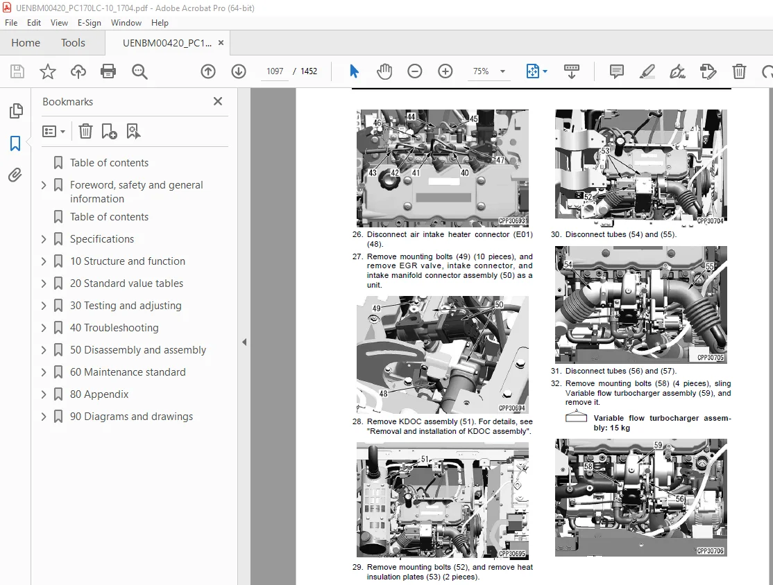
Removal and installation of KDOC assembly 1140
Removal 1140
Installation 1140
Removal and installation of KCCV assembly 1142
Removal 1142
Installation 1143
Removal and installation of air cleaner assembly 1147
Removal 1147
Installation 1148
Power train 1149
Removal and installation of travel motor and final drive assembly 1149
Removal 1149
Installation 1149
Disassembly and assembly of final drive assembly 1150
Disassembly 1150
Assembly 1152
Removal and installation of swing motor and swing machinery assembly 1159
Removal 1159
Installation 1160
Disassembly and assembly of swing machinery assembly 1161
Disassembly 1161
Assembly 1164
Removal and installation of swing circle assembly 1168
Removal 1168
Installation 1168
Undercarriage and frame 1169
Separation and connection of track shoe assembly 1169
Separation 1169
Installation 1170
Removal and installation of sprocket 1171
Removal 1171
Installation 1171
Removal and installation of idler and idler cushion assembly 1172
Removal 1172
Installation 1172
Disassembly and assembly of idler assembly 1173
Disassembly 1173
Assembly 1173
Disassembly and assembly of idler cushion assembly 1176
Disassembly 1176
Assembly 1176
Disassembly and assembly of track roller assembly 1178
Disassembly 1178
Assembly 1178
Disassembly and assembly of carrier roller assembly 1180
Disassembly 1180
Assembly 1181
Removal and installation of revolving frame assembly 1183
Removal 1183
Installation 1184
Removal and installation of counterweight assembly 1185
Removal 1185
Installation 1186
Hydraulic system 1187
Removal and installation of center swivel joint assembly 1187
Removal 1187
Installation 1189
Disassembly and assembly of center swivel joint assembly 1190
Disassembly 1190
Assembly 1190
Removal and installation of hydraulic tank assembly 1191
Removal 1191
Installation 1193
Removal and installation of main pump assembly 1195
Removal 1195
Installation 1197
Removal and installation of main pump input shaft oil seal 1198
Removal 1198
Installation 1198
Removal and installation of control valve assembly 1199
Removal 1199
Installation 1201
Disassembly and assembly of control valve assembly 1203
Assembly of control valve assembly 1204
Disassembly and assembly of work equipment PPC valve assembly 1205
Disassembly 1205
Assembly 1205
Disassembly and assembly of travel PPC valve assembly 1207
Disassembly 1207
Assembly 1207
Work equipment 1209
Removal and installation of work equipment assembly 1209
Removal 1209
Installation 1210
Disassembly and assembly of work equipment cylinder assembly 1212
Disassembly 1212
Assembly 1213
Cab and its attachments 1218
Removal and installation of operator’s cab assembly 1218
Removal 1218
Installation 1222
Removal and installation of operator cab glass (adhered glass) 1223
Removal 1225
Installation 1226
Removal and installation of front window assembly 1233
Removal 1233
Installation 1234
Removal and installation of floor frame assembly 1239
Removal 1239
Installation 1242
Removal and installation of air conditioner unit assembly 1244
Removal 1244
Installation 1247
Removal and installation of operator’s seat 1248
Removal 1248
Installation 1249
Removal and installation of seat belt 1250
Removal 1250
Installation 1250
Removal and installation of front wiper assembly 1251
Removal 1251
Installation 1253
Electrical system 1258
Removal and installation of air conditioner compressor assembly 1258
Removal 1258
Installation 1259
Removal and installation of air conditioner condenser assembly 1260
Removal 1260
Installation 1260
Removal and installation of engine controller assembly 1262
Removal 1262
Installation 1262
Removal and installation of pump controller assembly 1264
Removal 1264
Installation 1264
Removal and installation of machine monitor assembly 1267
Removal 1267
Installation 1268
Removal and installation of pump swash plate sensor 1269
Removal 1269
Installation 1269
Removal and installation of mass air flow and temperature sensor 1270
Removal 1270
Installation 1270
Removal and installation of KOMTRAX terminal assembly 1271
Removal 1271
Installation 1271
60 Maintenance standard 1273
Contents 1274
Engine and cooling system 1275
Engine mount 1275
Cooling system 1276
Power train 1277
Swing circle 1277
Swing machinery 1278
Final drive 1279
Sprocket 1281
Undercarriage and frame 1283
Track frame and idler cushion 1283
Idler 1285
Track roller 1287
Carrier roller 1288
Track shoe 1289
Triple grouser shoe 1292
Hydraulic system 1293
Hydraulic tank 1293
Main pump 1294
PC-EPC valve 1296
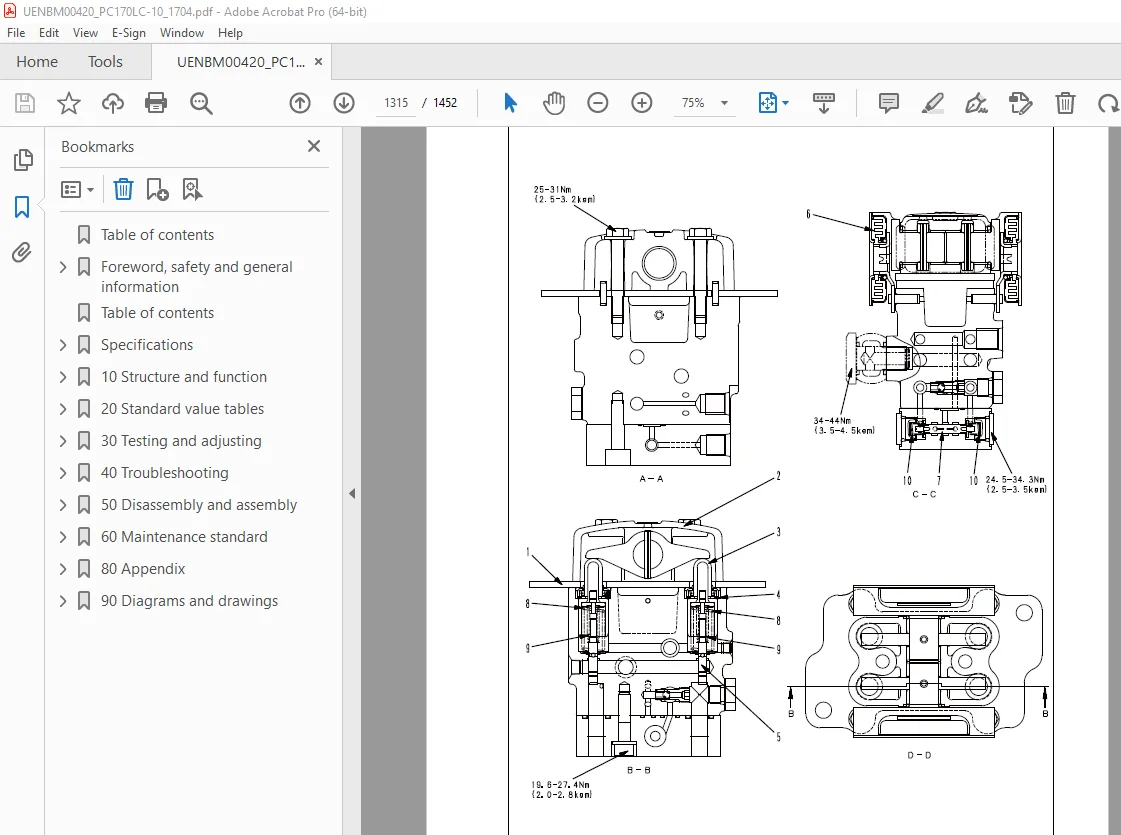
Control valve 1297
Travel motor 1308
Work equipment and swing PPC valve 1311
Travel PPC valve 1314
1st-line attachment PPC valve (with EPC valve) 1317
EPC valve 1319
2nd-line attachment PPC valve 1320
Solenoid valve 1322
Attachment circuit selector valve (for high-pressure circuit) 1323
Attachment circuit selector valve (for low-pressure circuit) 1324
Center swivel joint 1325
Work equipment 1326
Work equipment 1326
Dimensions of arm 1331
Dimensions of bucket 1333
Boom cylinder 1335
Arm cylinder 1336
Bucket cylinder 1337
80 Appendix 1339
Table of contents 1340
Air conditioner components 1341
Precautions for refrigerant 1341
Air conditioner component 1342
Configuration and function of refrigeration cycle 1345
Outline of refrigeration cycle 1346
Air conditioner unit 1348
Function 1349
Functions of major components 1351
Servomotor 1352
Expansion valve 1353
Dual pressure switch 1355
Function 1355
Air conditioner controller 1356
Compressor 1357
Function 1357
Air conditioner condenser 1358
Function 1358
Sunlight sensor 1360
Function 1360
Outer temperature sensor (outside air temperature sensor) 1361
Function 1361
Procedure for testing and troubleshooting 1362
Circuit diagram and arrangement of connector pins 1364
System diagram 1366
Input and output signals of the air conditioner controller 1367
Function 1367
Parts and connectors layout 1369
Details 1369
Testing air leakage 1373
Check) 1373
Testing with self-diagnosis function 1376
Testing outline 1376
How to open the electrical system abnormality record screen in service mode of the machine monitor 1376
Testing vent (mode) changeover 1379
Testing 1379
Testing FRESH/RECIRC air changeover 1381
Testing 1381
Testing sunlight sensor 1382
Testing 1382
Testing (dual) pressure switch for refrigerant 1383
Testing 1383
Testing relays 1384
Testing 1384
Troubleshooting chart 1 1385
Troubleshooting chart 2 1386
Information in troubleshooting table 1389
Information in troubleshooting table 1389
Failure code list related to air conditioner 1390
Failure code [879AKA] A/C Inner Sensor Open Circuit 1391
Failure code [879AKB] A/C Inner Sensor Short Circuit 1392
Failure code [879BKA] A/C Outer sensor Open Circuit 1393
Circuit diagram related to air conditioner outside air temperature sensor 1394
Failure code [879BKB] A/C Outer sensor Short Circuit 1395
Circuit diagram related to air conditioner outside air temperature sensor 1396
Failure code [879CKA] Ventilating Sensor Open Circuit 1397
Failure code [879CKB] Ventilating Sensor Short Circuit 1398
Failure code [879DKZ] Sunlight sensor Open or Short Circuit 1399
Circuit diagram related to sunlight sensor 1400
Failure code [879EMC] Ventilation Damper Abnormality 1401
Failure code [879FMC] Air Mix Damper Abnormality 1402
Failure code [879GKX] Refrigerant Abnormality 1403
A-1 Troubleshooting for power supply system (Air conditioner does not operate) 1404
A-2 Troubleshooting for compressor and refrigerant system (Air is not cooled) 1406
A-3 Troubleshooting for blower motor system (No air comes out or air flow is abnormal) 1409
A-4 Troubleshooting for FRESH/RECIRC air changeover 1411
Troubleshooting with gauge pressure 1413
Connection of service tool 1416
Precautions for disconnecting and connecting air conditioner piping 1418
Handling of compressor oil 1420
Desiccant replacement 1422
90 Diagrams and drawings 1425
Contents 1426
Hydraulic circuit diagram 1427
Symbols in hydraulic circuit diagram 1427
Hydraulic circuit diagram (1/2) 1431
Hydraulic circuit diagram (2/2) 1433
Electric circuit diagram 1435
Symbols in electric circuit diagram 1435
Electrical circuit diagram (1/7) 1439
Electrical circuit diagram (2/7) 1441
Electrical circuit diagram (3/7) 1443
Electrical circuit diagram (4/7) 1445
Electrical circuit diagram (5/7) 1447
Electrical circuit diagram (6/7) 1449
Electrical circuit diagram (7/7) 1451
DESCRIPTION:
Komatsu PC170LC-10 Hydraulic Excavator Shop Manual UENBM00420 – PDF DOWNLOAD
How to read the shop manual:
Composition of shop manual:
• This shop manual describes the technical information required for the services performed in a workshop.
The shop manual is divided into the following chapters for the convenience of use.
00. Index and foreword
• This section includes the index, foreword, safety and basic information.
01. Specification
• This section explains the specifications of the machine.
10. Structure and function
• This section explains the structure and function of the machine. The section of “Structure and function”
serves not only to give an understanding for the structure of each component, but also serves as reference
material for troubleshooting.
20. Standard value table
• The standard values for a new machine and trouble shooting are indicated. This standard value table is
used for testing and adjusting, and determining a failure at troubleshooting.
30. Testing and adjusting
• This section describes the measuring tools and how to measure, and how to adjust various parts. As for the
standard value and failure criterion, see the standard value table.
40. Troubleshooting
• This section describes the troubleshooting in a suspected area when a failure occurs and the remedy for
the failure. Troubleshooting is described by each failure mode.
50. Disassembly and assembly
• This section explains the procedures for removing, installing, disassembling, and assembling each part or
component and the special tools for the works as well as precautions for doing them safely. In addition,
tightening torque, and quantity and weight of coating material, oil, grease, and coolant required for the
works are also explained.
60. Maintenance standard
• This section describes the maintenance standard values for each component. This section gives the criterion
values for each component and required remedy at disassembly or maintenance.
80. Appendix
• The structure and function, testing and adjusting, and troubleshooting for all of the other components or
equipment which can not be separately classified are explained together in the appendix.
90. Diagrams and drawings
• This section gives hydraulic circuit diagrams and electrical circuit diagrams.
IMAGES PREVIEW OF THE MANUAL:
S.V 28/12/24


