
Komatsu PC200-6 PC200LC-6 PC210LC-6 PC220LC-6 PC250LC-6 Excavator Shop Manual PDF
$32.95
Komatsu PC200-6 PC200LC-6 PC210LC-6 PC220LC-6 PC250LC-6 Excavator Shop Manual – PDF DOWNLOAD
Description
Komatsu PC200-6 PC200LC-6 PC210LC-6 PC220LC-6 PC250LC-6 Excavator Shop Manual – PDF DOWNLOAD
FILE DETAILS:
Komatsu PC200-6 PC200LC-6 PC210LC-6 PC220LC-6 PC250LC-6 Excavator Shop Manual – PDF DOWNLOAD
Language : English
Pages : 721
Downloadable : Yes
File Type : PDF
IMAGES PREVIEW OF THE MANUAL:
DESCRIPTION:
Komatsu PC200-6 PC200LC-6 PC210LC-6 PC220LC-6 PC250LC-6 Excavator Shop Manual – PDF DOWNLOAD
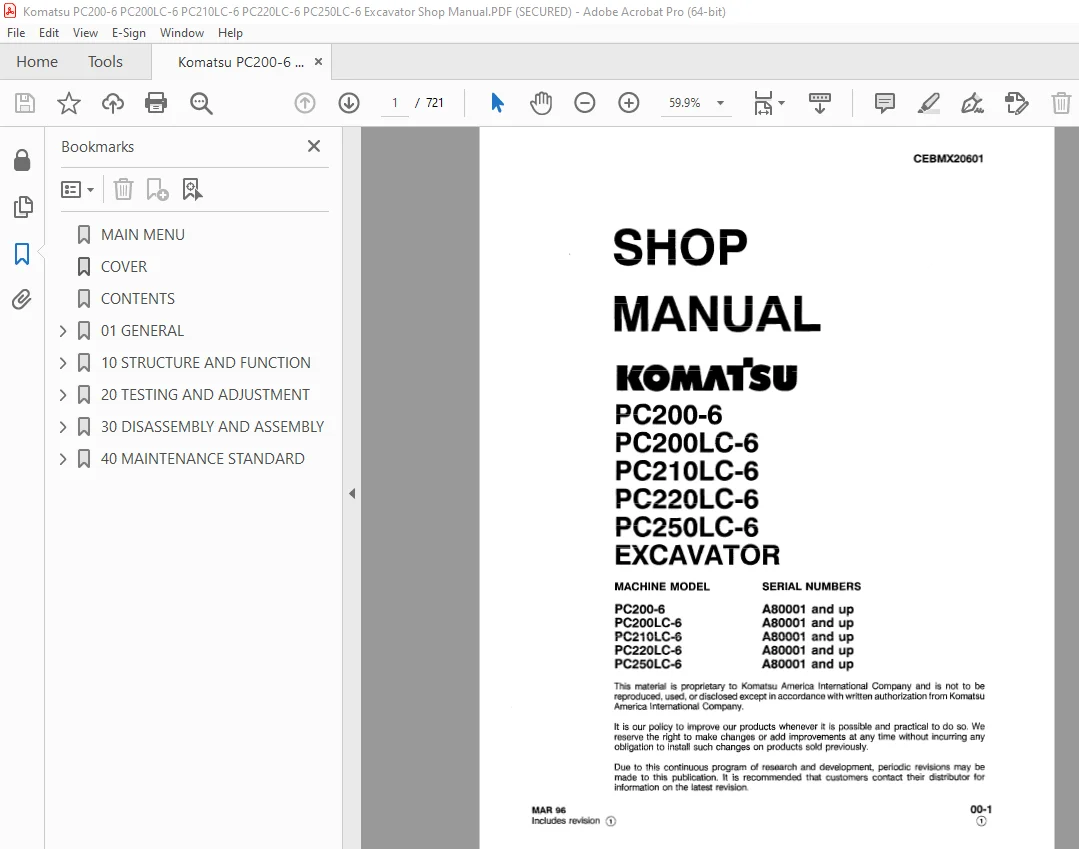
MACHINE MODEL SERIAL NUMBERS
PC200-6 A80001 and up
PC2OOLC-6 A80001 and up
PC21 OLC-6 A80001 and up
PC22OLC-6 A80001 and up
PC25OLC-6 A80001 and up
GENERAL PRECAUTIONS :
Mistakes in operation are extremely dangerous. Read the OPERATION & MAINTENANCE MANUAL carefully BEFORE operating the machine.
PREPARATIONS FOR WORK:
TABLE OF CONTENTS:
Komatsu PC200-6 PC200LC-6 PC210LC-6 PC220LC-6 PC250LC-6 Excavator Shop Manual – PDF DOWNLOAD
MAIN MENU 0
COVER 1
CONTENTS 10
01 GENERAL 25
GENERAL ASSEMBLY DRAWING 26
PC200-6, PC200LC-6, PC210LC-6 26
PC220LC-6, PC250LC-6 28
SPECIFICATIONS 31
PC200-6, PC200LC-6 31
PC210LC-6 33
PC220LC-6 35
PC250LC-6 37
WEIGHT TABLE 39
PC200-6, PC200LC-6 39
PC200-6, PC200LC-6 31
PC210LC-6 41
PC220LC-6, PC250LC-6 43
LIST OF LUBRICANT AND WATER 45
10 STRUCTURE AND FUNCTION 47
ENGINE RELATED PARTS 48
RADIATOR, OIL COOLER, AFTERCOOLER 49
POWERTRAIN 51
FINAL DRIVE 52
FINAL DRIVE 53
SWING CIRCLE 54
SWING MACHINERY 55
TRACK FRAME, RECOIL SPRING 56
TRACK SHOE 57
HYDRAULIC PIPING DRAWING 59
HYDRAULIC CIRCUIT DIAGRAM 60
HYDRAULIC CIRCUIT DIAGRAM 61
HYDRAULIC TANK 63
HYDRAULIC PUMP 64
LINE OIL FILTER 85
CONTROL VALVE 86
CLSS 95
SWING MOTOR 136
CENTER SWIVEL JOINT 139
TRAVEL MOTOR 140
TRAVEL MOTOR 142
VALVE CONTROL 151
WORK EQUIPMENT, SWING PPC VALVE 152
TRAVEL PPC VALVE 156
SERVICE PPC VALVE 160
SAFETY LOCK VALVE 163
PPC ACCUMULATOR 163
PPC SHUTTLE, TRAVEL JUNCTION VALVE 164
EPC, SOLENOID VALVE 171
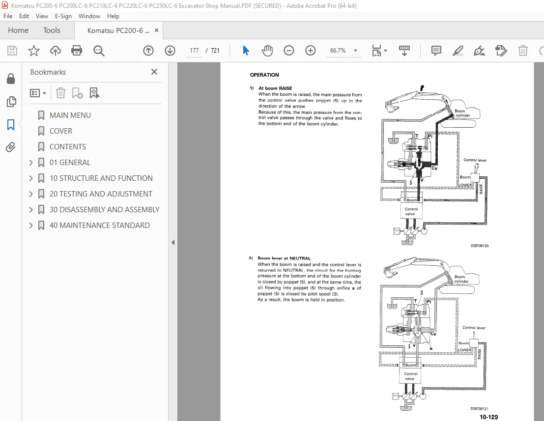
BOOM HOLDING VALVE 176
HYDRAULIC CYLINDER 179
ADDITIONAL FILTER FOR BREAKER 180
WORK EQUIPMENT 181
ELECTRICAL WIRING DIAGRAM 182
ELECTRICAL CIRCUIT DIAGRAM (1/2) 184
ENGINE CONTROL SYSTEM 186
ELECTRONIC CONTROL SYSTEM 191
MACHINE MONITOR SYSTEM 216
20 TESTING AND ADJUSTMENT 223
TABLE OF JUDGEMENT STANDARD VALUE 224
STANDARD VALUE FOR ELECTRICAL PARTS 236
TOOLS FOR TESTING, ADJUSTING AND TROUBLESHOOTING 245
MEASURING ENGINE SPEED 246
MEASURING EXHAUST GAS COLOR 247
ADJUSTING VALVE CLEARANCE 248
MEASURING COMPRESSION PRESSURE 249
MEASURING BLOWBY PRESSURE 249
TESTING AND ADJUSTING FUEL INJECTION TIMING 250
MEASURING ENGINE OIL PRESSURE 251
TESTING AND ADJUSTING ALTERNATOR FAN BELT TENSION 252
TESTING AND ADJUSTING BELT TENSION FOR AIR CONDITIONER COMPRESSOR 252
ADJUSTING ENGINE SPEED SENSOR 253
TESTING AND ADJUSTING GOVERNOR MOTOR LEVER STROKE 254
TESTING CLEARANCE OF SWING CIRCLE BEARING 255
TESTING AND ADJUSTING TRACK SHOE TENSION 256
TESTING AND ADJUSTING HYDRAULIC PRESSURE IN WORK EQUIPMENT, SWING, AND TRAVEL CIRCUIT 257
TESTING AND ADJUSTING TVC VALVE OUTPUT PRESSURE (SERVO PISTON INPUT PRESSURE) 260
TESTING AND ADJUSTING LS VALVE OUTPUT PRESSURE (SERVO PISTON INPUT PRESSURE) AND LS DIFFERENTIAL PRESSURE 262
TESTING AND ADJUSTING CONTROL PUMP CONTROL CIRCUIT OIL PRESSURE 265
TESTING EPC VALVE, SOLENOID VALVE OUTPUT PRESSURE 267
MEASURING PPC VALVE OUTPUT PRESSURE AND TESTING PPC SHUTTLE VALVE 269
ADJUSTING WORK EQUIPMENT, SWING PPC VALVE 271
ADJUSTING TRAVEL LEVER 272
TESTING TRAVEL DEVIATION 273
TESTING LOCATIONS CAUSING HYDRAULIC DRIFT OF WORK EQUIPMENT 274
MEASURING OIL LEAKAGE 276
RELEASING REMAINING PRESSURE IN HYDRAULIC CIRCUIT 277
BLEEDING AIR 278
TROUBLESHOOTING 280
POINTS TO REMEMBER WHEN TROUBLESHOOTING 281
SEQUENCE OF EVENTS IN TROUBLESHOOTING 282
PRECAUTION WHEN CARRYING OUT MAINTENANCE 283
CHECKS BEFORE TROUBLESHOOTING 290
CONNECTOR TYPES AND MOUNTING LOCATIONS 291
CONNECTION TABLE FOR CONNECTOR PIN NUMBERS 295
EXPLANATION OF CONTROL MECHANISM FOR ELECTRICAL SYSTEM 308
DISPLAY METHOD AND SPECIAL FUNCTIONS OF MONITOR PANEL 309
METHOD OF USING JUDGEMENT TABLE 318
METHOD OF USING TROUBLESHOOTING CHARTS 320
DETAILS OF TROUBLESHOOTING AND TROUBLESHOOTlNG PROCEDURE 322
TROUBLESHOOTING OF ENGINE THROTTLE CONTROLLER SYSTEM (E MODE) 327
TROUBLESHOOTING 280
POINTS TO REMEMBER WHEN CARRYING OUT TROUBLESHOOTING OF ENGINE THROTTLE CONTROLLER SYSTEM 328
ACTION TAKEN BY CONTROLLER WHEN ABNORMALITY OCCURS AND PROBLEMS ON MACHINE 329
JUDGEMENT TABLE FOR ENGINE THROTTLE CONTROLLER AND ENGINE RELATED PARTS 331
ENGINE THROTTLE CONTROLLER SYSTEM CIRCUIT DIAGRAM 332
E-1 Abnormality in engine throttle controller power system (engine speed stays at low idling) 333
E-2 [E3:08] Abnormality in fuel control dial input value is displayed 334
E-3 [E3:17] Abnormality (disconnection) in governor motor drive system is displayed 335
E-4 [E3:18] Abnormality (short circuit) in governor motor drive system is displayed 336
E-5 [E3:01] Abnormality in network reception system is displayed 337
E-6 [E3:05] Abnormality in model code is displayed 339
E-7 [E3:06] Abnormality in governor potentiometer system is displayed 340
E-8 [E3:07] Abnormality in pump controller throttle system is displayed 341
E-10 [E3:16] Abnormality (step-out) in governor motor system is displayed 342
E-11 Engine does not start 343
E-12 Engine speed is irregular 345
E-13 Lack of output (engine high idling speed is too low) 349
E-14 Engine does not stop 351
E-15 Defective operation of battery relay system (engine does not stop) 353
TROUBLESHOOTING OF ENGINE (S MODE) 354
METHOD OF USING TROUBLESHOOTING CHART 355
S-1 Starting performance is poor (Starting always takes time) 359
S-2 Engine does not start 360
Engine does not turn 360
Engine turns but no exhaust gas comes out (Fuel is not being injected) 361
Exhaust gas comes out but engine does not start (Fuel is being injected) 362
S-3 Engine does not pick up smoothly (Follow-up is poor) 363
S-4 Engine stops during operations 364
S-5 Engine does not rotate smoothly 365
S-6 Engine lacks output (no power) 366
S-7 Exhaust gas is black (incomplete combustion) 367
S-8 Oil consumption is excessive (or exhaust gas is blue) 368
S-9 Oil becomes contaminated quickly 369
S-10 Fuel consumption is excessive 370
S-11 Oil is in cooling water, or water spurts back, or water level goes down 371
S-12 Oil pressure lamp lights up (drop in oil pressure) 372
S-13 Oil level rises 373
S-14 Water temperature becomes too high (overheating) 374
S-15 Abnormal noise is made 375
S-16 Vibration is excessive 376
TROUBLESHOOTING OF PUMP CONTROLLER SYSTEM (C MODE) 377
POINTS TO REMEMBER WHEN TROUBLESHOOTING PUMP CONTROLLER SYSTEM 378
ACTION TAKEN BY CONTROLLER WHEN ABNORMALITY OCCURS AND PROBLEMS ON MACHINE 379
JUDGEMENT TABLE FOR PUMP CONTROLLER AND HYDRAULIC RELATED PARTS 383
PUMP CONTROLLER SYSTEM CIRCUIT DIAGRAM 384
C-1 Abnormality in pump controller power source system (swing brake is not canceled, etc ) 385
C-2 [E2:32][E2:36] Sort circuit in front/rear pump TVC solenoid system is displayed 386
C-3 [E2:33][E2:37] Disconnection in front/rear pump TVC solenoid system is displayed 388
C-4 [E2:03] Short circuit in swing brake solenoid system is displayed 390
C-5 [E2:13] Disconnection in swing brake solenoid system is displayed 392
C-6 394
[E2:02] Short circuit in LS select solenoid system is displayed 394
[E2:04] Short circuit in pump merge-divider solenoid system is displayed 394
[E2:05] Short circuit in 2-stage relief solenoid system is displayed 394
[E2:06] Short circuit in travel speed solenoid system is displayed 394
C-7 396
[E2:12] Disconnection in LS select solenoid system is displayed 396
[E2:14] Disconnection in pump merge-divider solenoid system is displayed 396
[E2:15] Disconnection in 2-stage relief solenoid system is displayed 396
[E2:16] Disconnection in travel speed solenoid system is displayed 396
C-8 [E2:17] Model selection input error is displayed 398
C-9 [E2:18] Network response overtime is displayed 399
C-10 [E2:22] Short circuit in LS control EPC solenoid system is displayed 401
C-11 [E2:23] Disconnection in LS control EPC solenoid system is displayed 402
C-12 403
[E2:24] Abnormality in front pump pressure sensor system is displayed 403
[E2:25] Abnormality in rear pump pressure sensor system is displayed 403
C-13 [E2:26] Abnormality in pump pressure sensor power source system is displayed 405
C-14 [E2:27] Abnormality in engine speed sensor system is displayed 406
C-15 [E2:28] Abnormality in auto-deceleration output system is displayed 407
TROUBLESHOOTING OF PUMP CONTROLLER INPUT SIGNAL SYSTEM (F MODE) 408
F-1 Bit pattern 20-(1) Swing oil pressure switch does not light up 409
F-2 Bit pattern 20-(2) Travel oil pressure switch does not light up 410
F-3 Bit pattern 20-(3) Boom LOWER oil pressure switch does not light up 411
F-4 Bit pattern 20-(4) Boom RAISE oil pressure switch does not light up 412
F-5 Bit pattern 20-(5) Arm IN oil pressure switch does not light up 413
F-6 Bit pattern 20-(6) Arm OUT oil pressure switch does not light up 414
F-7 Bit pattern 21-(1) Bucket CURL oil pressure switch does not light up 415
F-8 Bit pattern 21-(2) Bucket DUMP oil pressure switch does not light up 416
F-9 Bit pattern 21-(3) Swing lock switch does not light up 417
F-10 Engine speed is not displayed in monitoring code 10 (abnormality in engine speed sensor system) 418
F-11 Bit pattern 22-(5) Kerosene mode connection does not light up 419
F-12 Bit pattern 22-(6) L H knob switch does not light up 420
TROUBLESHOOTING OF HYDRAULIC AND MECHANICAL SYSTEM (H MODE) 421
TABLE OF FAILURE MODES AND CAUSES FOR HYDRAULIC AND MECHANICAL SYSTEM 422
PUMP MERGE-DIVIDER LOGIC 424
ALL WORK EQUIPMENT, TRAVEL, SWING 426
H-1 Speeds of all work equipment, swing, travel and slow or lack power 426
H-2 There is excessive drop in engine speed, or engine stall 428
H-3 No work equipment, travel, swing move 429
H-4 Abnormal noise generated (around pump) 429
H-5 Auto-deceleration does not work (when PPC shuttle valve is cause) 430
H-6 Fine control ability is poor or response is poor 430
WORK EQUIPMENT 421
H-7 Boom is slow or lacks power 431
H-8 Arm is slow or lacks power 433
H-9 Bucket is slow or lacks power 435
H-10 Work equipment (boom, arm, bucket) does not move (but travel and swing are normal) 436
H-11 Excessive hydraulic drift (boom, arm, bucket) 436
H-12 Excessive time lag (engine at low idling) 437
H-13 Lack of power when pressure rises 437
H-14 Other equipment moves when single circuit is relieved 437
H-15 In L/O, F/O modes, work equipment speed is faster than specified speed 438
COMPOUND OPERATIONS 421
H-16 In Compound operations, work equipment with larger load is slow 438
H-17 In swing + boom RAISE, boom RAISE is slow 439
H-18 In swing + arm OUT, arm OUT is slow 439
H-19 In swing + travel, travel speed drops excessively 439
TRAVEL SYSTEMS 421
H-20 Travel deviation 440
H-21 Travel speed is slow 441
H-22 Steering does not turn easily or lacks power 443
H-23 Travel speed doeas not switch or is faster than specified speed 445
H-24 Travel does not move (one side only) 445
SWING SYSTEM 421
H-25 Does not swing 446
H-26 Swing acceleration is poor or swing speed is slow (both left and right, one direction only) 447
H-27 Excessive overrun when stopping swing 449
H-28 Excessive shock when stopping swing (one direction only) 450
H-29 Excessive abnormal noise when stopping swing 450
H-30 Excessive hydraulic drift of swing 451
H-31 Swing speed is faster than specified swing speed 452
TROUBLESHOOTING OF MACHINE MONITOR SYSTEM (M MODE) 453
ACTION TAKEN BY MONITOR PANEL WHEN ABNORMALITY OCCRS AND PROBLEMS ON MACHINE 454
MACHINE MONITOR SYSTEM CIRCUIT DIAGRAM 455
M-1 [E1:01] Abnormality in error data is displayed 456
M-2 [E1:02] Error in clock data is displayed 456
M-3 [E1:03] Short circuit in buzzer output or contact of 24V wiring harness with buzzer drive harness is displayed 456
M-4 When starting switch is turned on, none of lamps on monitor panel light up for 3 seconds 457
M-5 When starting switch is turned ON, monitor panel-lamps all stay lighted up and do not go out 458
M-6 When starting switch is turned ON, items lighted up on monitor panel are different from machine model 458
M-7 When starting switch is turned ON (engine stopped), CHECK items flash (fluids level for CHECK items are at specified level) 459
M-8 Preheating is not being used but preheating display lights up 461
M-9 When starting switch is turned ON and engine is started, CHECK items flash 462
M-10 When starting switch is turned ON (engine stopped), CAUTION items flash 464
M-11 When starting switch is turned ON and engine is started, CAUTION items flash 466
M-12 When starting switch is turned ON (engine stopped), buzzer does not sound for 1 second 469
M-13 Liquid crystal night lighting on monitor panel does not light up (liquid crystal display is normal) 470
M-14 Coolant temperature gauge does not rise 471
M-15 Collant temperature gauge does not give any display (none of gauge lamps light up during operation) 472
M-16 Fuel level gauge always displays FULL 473
M-17 Fuel level gauge does not give display 473
M-18 Swing lock switch is turned ON (LOCK) but monitor panel parking display does not light up 474
M-19 Swing lock prolix switch is ON (prolix), but monitor panel parking display does not flash 474
M-20 Defective fuel level sensor system 475
M-21 Defective coolant temperature sensor system 476
M-22 Defective engine oil level sensor system 477
M-23 Defective coolant level sensor system 478
M-24 Defective hydraulic oil level sensor system 479
M-25 Working light, panel lighting do not light up, or switch is not being used but lights light up 480
M-26 Wiper does not work or switch is not being used but wiper is actuated 482
30 DISASSEMBLY AND ASSEMBLY 486
METHOD OF USING MANUAL 490
PRECAUTIONS WHEN CARRYING OUT OPERATION 491
SPECIAL TOOL LIST 493
STARTING MOTOR 498
REMOVAL 498
INSTALLATION 498
ALTERNATOR 498
REMOVAL 498
INSTALLATION 498
AIR CONDITIONER COMPRESSOR 499
REMOVAL 499
INSTALLATION 499
AIR CONDITIONER CONDENSER 500
REMOVAL 500
INSTALLATION 500
ENGINE OIL COOLER CORE 501
REMOVAL 501
INSTALLATION 501
FUEL INJECTION PUMP 502
REMOVAL 502
INSTALLATION 504
WATER PUMP 505
REMOVAL 505
INSTALLATION 505
NOZZLE HOLDER 506
REMOVAL 506
INSTALLATION 506
TURBOCHARGER 507
REMOVAL 507
INSTALLATION 507
THERMOSTAT 508
REMOVAL 508
INSTALLATION 508
ENGINE FRONT OIL SEAL 509
REMOVAL 509
INSTALLATION 509
ENGINE REAR OIL SEAL 510
REMOVAL 510
INSTALLATION 510
GOVERNOR MOTOR 511
REMOVAL 511
INSTALLATION 511
CYLINDER HEAD 512
REMOVAL 512
INSTALLATION 514
AFTERCOOLER 516
REMOVAL 516
INSTALLATION 516
HYDRAULIC OIL COOLER – PC200-6, PC210-6 517
REMOVAL 517
INSTALLATION 517
HYDRAULIC OIL COOLER – PC220-6, PC250-6 518
REMOVAL 518
INSTALLATION 518
RADIATOR HYDRAULIC OIL COOLER – PC200-6, PC210-6 519
REMOVAL 519
INSTALLATION 520
RADIATOR HYDRAULIC OIL COOLER – PC220-6, PC250-6 521
REMOVAL 521
INSTALLATION 522
ENGINE HYDRAULIC PUMP 523
REMOVAL 523
INSTALLATION 526
DAMPER 527
REMOVAL 527
INSTALLATION 527
FUEL TANK 528
REMOVAL 528
INSTALLATION 528
CENTER SWIVEL JOINT 529
REMOVAL 529
INSTALLATION 529
DISASSEMBLY 530
ASSEMBLY 530
FINAL DRIVE 531
REMOVAL 531
INSTALLATION 531
FINAL DRIVE PC200-6 6, PC200LC-6, PC210LC-6, PC220LC-6 532
DISASSEMBLY 532
ASSEMBLY 535
FINAL DRIVE PC250LC 539
DISASSEMBLY 539
ASSEMBLY 542
SPROCKET 547
REMOVAL 547
INSTALLATION 547
TRAVEL MOTOR 548
DISASSEMBLY 548
ASSEMBLY 553
SWING MOTOR 561
REMOVAL 561
INSTALLATION 561
SWING MACHINERY 562
REMOVAL 562
INSTALLATION 562
DISASSEMBLY 563
ASSEMBLY 566
REVOLVING FRAMES 570
REMOVAL 570
INSTALLATION 571
SWING CIRCLE 572
REMOVAL 572
INSTALLATION 573
IDLER, RECOIL SPRING 574
REMOVAL 574
INSTALLATION 574
RECOIL SPRING 575
DISASSEMBLY 575
ASSEMBLY 576
IDLER 577
DISASSEMBLY 577
ASSEMBLY 578
TRACK ROLLER 580
REMOVAL 580
INSTALLATION 580
DISASSEMBLY 582
ASSEMBLY 583
CARRIER ROLLER 585
REMOVAL 585
INSTALLATION 585
DISASSEMBLY 586
ASSEMBLY 587
TRACK SHOE 589
REMOVAL 589
INSTALLATION 589
HYDRAULIC TANK 590
REMOVAL 590
INSTALLATION 591
CONTROL PUMP 592
REMOVAL 592
INSTALLATION 592
MAIN PUMP 593
REMOVAL 593
INSTALLATION 594
DISASSEMBLY 595
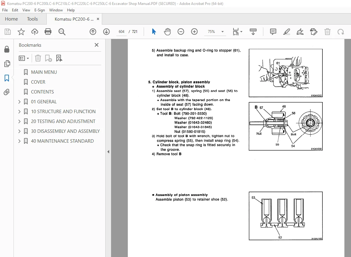
ASSEMBLY 601
MAIN PUMP INPUT SHAFT OIL SEAL 617
REMOVAL 617
INSTALLATION 617
CONTROL VALVE 618
REMOVAL 618
INSTALLATION 619
REMOVAL 7 – SPOOL 620
INSTALLATION 7 – SPOOL 621
DISASSEMBLY 622
ASSEMBLY 624
PUMP MERGE-DIVIDER VALVE 626
DISASSEMBLY 626
ASSEMBLY 626
PRESSURE COMPENSATION VALVE 627
DISASSEMBLY 627
ASSEMBLY 627
MAIN RELIEF VALVE 628
DISASSEMBLY 628
ASSEMBLY 629
TVC – LS VALVE 630
FRONT PUMP 630
REMOVAL 630
INSTALLATION 630
REAR PUMP 631
REMOVAL 631
INSTALLATION 631
LS CONTROL EPC VALVE 632
REMOVAL 632
INSTALLATION 632
SOLENOID VALVE 633
REMOVAL 633
INSTALLATION 633
WORK EQUIPMENT/SWING PPC VALVE 634
REMOVAL 634
INSTALLATION 634
DISASSEMBLY 635
ASSEMBLY 636
TRAVEL PPC VALVE 637
REMOVAL 637
INSTALLATION 637
DISASSEMBLY 638
ASSEMBLY 638
BOOM LOCK VALVE 640
REMOVAL 640
INSTALLATION 640
BOOM CYLINDER 641
REMOVAL 641
INSTALLATION 642
ARM CYLINDER 643
REMOVAL 643
INSTALLATION 644
BUCKET CYLINDER 645
REMOVAL 645
INSTALLATION 646
HYDRAULIC CYLINDER 647
DISASSEMBLY 647
ASSEMBLY 649
WORK EQUIPMENT 652
REMOVAL 652
INSTALLATION 653
BUCKET 654
REMOVAL 654
INSTALLATION 655
ARM 656
REMOVAL 656
INSTALLATION 657
BUCKET ARM 658
REMOVAL 658
INSTALLATION 659
BOOM 660
REMOVAL 660
INSTALLATION 661
OPERATOR’S CAB 662
REMOVAL 662
INSTALLATION 664
COUNTERWEIGHT 665
REMOVAL 665
INSTALLATION 665
ENGINE THROTTLE CONTROLLER 666
REMOVAL 666
INSTALLATION 666
PUMP CONTROLLER 667
REMOVAL 667
INSTALLATION 667
MONITOR 668
REMOVAL 668
INSTALLATION 668
40 MAINTENANCE STANDARD 669
FINAL DRIVE 670
FINAL DRIVE 672
SWING MACHINERY 674
SWING CIRCLE 676
TRACK FRAME, RECOIL SPRING 677
TRACK FRAME, RECOIL SPRING 678
IDLER 679
IDLER 681
CARRIER ROLLER 683
CARRIER ROLLER 684
TRACK ROLLER 685
TRACK ROLLER 686
TRACK SHOE 687
TRACK SHOE 689
HYDRAULIC PUMP 691
CONTROL PUMP, RELIEF VALVE 692
SWING MOTOR 700
TRAVEL MOTOR 701
TRAVEL MOTOR 702
WORK EQUIPMENT, SWING PPC VALVE 703
TRAVEL PPC VALVE 704
SERVICE PPC VALVE 705
PPC SHUTTLE, TRAVEL JUNCTION VALVE 706
EPC, SOLENOID VALVE 708
CENTER SWIVEL JOINT 709
BOOM HOLDING VALVE 710
HYDRAULIC CYLINDER 711
HYDRAULIC CYLINDER 713
WORK EQUIPMENT 715
S.V 11/12/24



