Komatsu PC200-8 PC200LC-8 Hydraulic Excavator Shop Manual 1001 and up – PDF DOWNLOAD
Original price was: $84.95.$26.95Current price is: $26.95.
Komatsu PC200-8 PC200LC-8 Hydraulic Excavator Shop Manual
SERIAL NUMBERS :
PC200- 1001 and up
PC200LC-1001 and up
Description
Komatsu PC200-8 PC200LC-8 Hydraulic Excavator Shop Manual 1001 and up
FILE DETAILS:
Komatsu PC200-8 PC200LC-8 Hydraulic Excavator Shop Manual 1001 and up
Brands: Komatsu
Equipment Type: Hydraulic Excavator
Manuals Type: Shop Manual
Machine Model: PC200-8, PC200LC-8
Serial Number: 1001 and up
Book Code: SEN05221-05
Language: English
Pages: 1284
File Format: Portable Document Format (PDF)
DESCRIPTION:
Komatsu PC200-8 PC200LC-8 Hydraulic Excavator Shop Manual 1001 and up
How to read the shop manual:
1. Composition of shop manual
This shop manual contains the necessary technical information for services performed in a workshop. For ease of understanding, the manual is divided into the following sections.
00. Index and foreword
This section contains the index, foreword, safety and basic information. If any revision is made, the LIST OF REVISED PAGES will be added.
01. Specification:
This section explains the specifications of the machine.
10. Structure and function:
This section explains the structure and function of each component. It serves not only to give an understanding for the structure of each component, but also serves as reference material for troubleshooting.
20. Standard value table:
This section explains the standard values for new machine and judgement criteria for testing, adjusting, and troubleshooting. This standard value table is used to check the standard values in testing and adjusting and to judge parts in troubleshooting.
30. Testing and adjusting:
This section explains measuring tools and measuring methods for testing and adjusting, as well as the adjusting method of each part. The standard values and judgment criteria for “Testing and adjusting” are
explained in “Standard value table”.
40. Troubleshooting:
This section explains how to find out failed parts and how to repair them. The troubleshooting is dividedby failure modes. The “S mode” of the troubleshooting related to the engine may be also explained in the
Chassis volume and Engine volume. In this case, see the Chassis volume.
50. Disassembly and assembly:
This section explains the special tools and procedures for removing, installing, disassembling, and assembling each component, as well as precautions for them. In addition, tightening torque, and quantity and
weight of coating material, oil, grease, and coolant necessary for the work are also explained.
60. Maintenance standard:
This section gives maintenance standard values of each component. The maintenance standard sub-section explains the criteria and remedies for disassembly and service.
80. Appendix:
This section explains the structure, function, testing, adjusting, and troubleshooting for the equipment not classifiable in other sections.
90. Diagrams and drawings (chassis volume) /Repair and replacement of parts (engine volume):
- Chassis volume
This section gives hydraulic circuit diagrams and electrical circuit diagrams. - Engine volume
This section explains the method of remanufacturing and repairing engine and replacing parts.
TABLE OF CONTENTS:
Komatsu PC200-8 PC200LC-8 Hydraulic Excavator Shop Manual 1001 and up
Shop Manual, contents binder, binder label and tabs
00 Index and Foreword
Index SEN05223-05
Composition of shop manual 2
Table of contents 4
Foreword and general information SEN05224-02
Safety notice 2
How to read the shop manual 7
Explanation of terms for maintenance standard 9
Handling of hydraulic components 11
Method of disassembling and connecting push-pull type coupler 13
Handing of electric equpment 16
How to read electric wire code 26
Precautions when carrying out work 31
Handling of hybrid devices and high-voltage wirings 34
Standard tightening torque table 42
Conversion table 46
01 Specification
Specification and technical data SEN05226-02
Outline of hybrid system 2
Specification dimension drawings 3
Working range diagram 4
Specifications 5
Weight table 8
Table of fuel, coolant and lubricants 10
10 Structure,function and maintenance standard
Engine and cooling system SEN05228-00
Engine related parts 2
Radiator, oil cooler, aftercooler and fuel cooler 3
Hyblid Relation SEN05229-02
Configuration and safety functions of hybrid system 2
Cooling system of hybrid component 6
Motor generator 8
Swing electric motor 9
Electric control unit 10
High-voltage wiring (power cable) 11
Power train SEN05230-00
Power train 2
Final drive 4
Swing machinery 6
Swing circle 8
Undercarriage and frame SEN05231-01
Track frame and recoil spring 2
Idler 4
Carrier roller 6
Track roller 7
Track shoe 8
Hydraulic system, Part 1 SEN05232-01
Hydraulic components layout drawing 2
SEN05223-05
PC200, 200LC-8E0 (Hybrid) 00-100 5
100 Index
Table of contents
Hydraulic tank and filter 4
Hydraulic pump 6
Hydraulic system, Part 2 SEN05233-01
Control valve 2
CLSS 13
Functions and operation by valve 18
Hydraulic system, Part 3 SEN05234-02
Center swivel joint 2
Travel motor 4
PPC valve 15
Valve control 30
Solenoid valve 32
Accumulator 34
Hydraulic cylinder 36
Work equipment SEN05235-00
Dimensions of components 2
Cab and its attachments SEN05236-00
Air conditioner piping 2
Electrical system SEN05237-01
Engine control 2
Electrical control system 10
Monitor system 35
Sensors 60
KOMTRAX system 63
20 Standard value table
Standard service value table SEN05239-00
Standard value table for engine related parts 2
Standard value table for chassis related parts 3
30 Testing and adjusting
Testing and adjusting, Part 1 SEN05241-01
Tools for testing, adjusting and troubleshooting 3
Testing engine speed 7
Testing boost pressure 9
Checking exhaust gas color 10
Adjusting valve clearance 11
Testing compression pressure 13
Testing blowby pressure 16
Testing engine oil pressure 17
Handling fuel system parts 18
Releasing remaining pressure from fuel system 18
Testing fuel system pressure 19
Cylinder cut-out test mode operation 21
No injection cranking operation 21
Testing fuel return rate and leakage 22
Bleeding air from fuel circuit 26
Testing fuel circuit for leakage 27
Handling of controller high-voltage circuit 28
Testing and adjusting air conditioner compressor belt tension 29
Replacement of fan belt 30
Testing swing circle bearing clearance 31
Testing and adjusting track tension 32
100 Index
Table of contents
00-100 6 PC200, 200LC-8E0 (Hybrid)
SEN05223-05
Testing and adjusting hydraulic oil pressure in work equipment and travel circuits 34
Testing source pressure of control circuit 37
Testing and adjusting oil pressure in pump PC control circuit 38
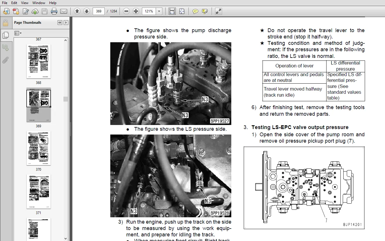
Testing and adjusting oil pressure in pump LS control circuit 41
Testing solenoid valve output pressure 45
Testing PPC valve output pressure 48
Adjusting play of work equipment and swing PPC valves 50
Checking parts which cause hydraulic drift of work equipment 51
Releasing remaining pressure from hydraulic circuit 53
Testing oil leakage 54
Bleeding air from each part 56
Checking cab tipping stopper 58
Adjusting mirrors 59
Angle adjustment of rear view camera 61
Testing swing brake 62
Cleaning and replacement of oil filter of electric swing motor 64
Operation check of swing emergency stop switch 65
Testing and adjusting, Part 2 SEN05242-02
Special functions of machine monitor 2
Testing and adjusting, Part 3 SEN05243-01
Handling voltage circuit of engine controller 2
Precautions related to hybrid machines 3
Preparation work for troubleshooting of electrical system 4
Procedure for testing diodes 10
Pm Clinic service 11
40 Troubleshooting
Failure code table and fuse locations SEN05245-02
Failure code table 2
Fuse locations 8
General Information on troubleshooting SEN05246-01
Points to remember when troubleshooting 2
Sequence of events in troubleshooting 3
Check before troubleshooting 4
Classification and procedures for troubleshooting 5
Probable problems and troubleshooting No 7
Information in troubleshooting table 9
Connection table for connector pin numbers 11
T-adapter and box table 47
Troubleshooting by failure code, Part 1 SEN05247-00
Failure code [989L00] Engine Controller Lock Caution 1 3
Failure code [989M00] Engine Controller Lock Caution 2 3
Failure code [989N00] Engine Controller Lock Caution 3 4
Failure code [AA10NX] Air Cleaner Clogging 5
Failure code [AB00KE] Charge Voltage Low 6
Failure code [B@BAZG] Eng Oil Press Low 8
Failure code [B@BAZK] Eng oil level low 8
Failure code [B@BCNS] Eng Water Overheat 9
Failure code [B@BCZK] Eng Water Level Low 9
Failure code [B@HANS] Hydr oil overheat 10
Failure code [CA111] EMC Critical Internal Failure 11
Failure code [CA115] Eng Ne and Bkup Speed Sens Error 11
Failure code [CA122] Chg Air Press Sensor High Error 12
SEN05223-05
PC200, 200LC-8E0 (Hybrid) 00-100 7
100 Index
Table of contents
Failure code [CA123] Chg Air Press Sensor Low Error 16
Failure code [CA132] Throttle Sensor Low Error 18
Failure code [CA144] Coolant temp sensor high error 20
Failure code [CA145] Coolant temp sensor low error 22
Failure code [CA153] Chg Air Temp Sensor High Error 24
Failure code [CA154] Chg Air Temp Sensor Low Error 26
Failure code [CA155] Chg Air Temp High Speed Derate 28
Failure code [CA187] Sens Supply 2 Volt Low Error 30
Failure code [CA221] Ambient Press Sens High Error 32
Failure code [CA222] Ambient Press Sens Low Error 34
Failure code [CA227] Sens Supply 2 Volt High Error 36
Failure code [CA234] Eng Overspeed 37
Failure code [CA238] Ne Speed Sens Supply Volt Error 38
Failure code [CA271] IMV/PCV1 Short Error 39
Failure code [CA272] IMV/PCV1 Open Error 40
Failure code [CA322] Inj #1 (L#1) Open/Short Error 42
Failure code [CA324] Inj #3 (L#3) Open/Short Error 44
Failure code [CA331] Inj #2(L#2) Open/Short Error 46
Failure code [CA332] Inj #4 (L#4) Open/Short Error 48
Troubleshooting by failure code, Part 2 SEN05248-00
Failure code [CA342] Calibration Code Incompatibility 3
Failure code [CA351] Injectors Drive Circuit Error 3
Failure code [CA352] Sens Supply 1 Volt Low Error 4
Failure code [CA386] Sens Supply 1 Volt High Error 6
Failure code [CA428] Water in Fuel Sensor High Error 8
Failure code [CA429] Water in Fuel Sensor Low Error 10
Failure code [CA435] Eng Oil Press Sw Error 12
Failure code [CA441] Battery Voltage Low Error 14
Failure code [CA442] Battery Voltage High Error 16
Failure code [CA449] Rail Press Very High Error 18
Failure code [CA451] Rail Press Sensor High Error 20
Failure code [CA452] Rail Press Sensor Low Error 22
Failure code [CA488] Chg Air Temp High Torque Derate 24
Failure code [CA553] Rail Press High Error 24
Failure code [CA559] Rail Press Low Error 25
Failure code [CA689] Eng Ne Speed Sensor Error 26
Failure code [CA731] Eng Bkup Speed Sens Phase Error 28
Failure code [CA757] All Continuous Data Lost Error 30
Failure code [CA778] Eng Bkup Speed Sensor Error32
Failure code [CA1633] KOMNET Datalink Timeout Error 34
Failure code [CA2185] Throt Sens Sup Volt High Error 35
Failure code [CA2186] Throt Sens Sup Volt Low Error 36
Failure code [CA2249] Rail Press Very Low Error 37
Failure code [CA2311] IMV Solenoid Error 37
Failure code [CA2555] Grid Htr Relay Volt High Error 38
Failure code [CA2556] Grid Htr Relay Volt Low Error 40
Failure code [D19JKZ] Personal Code Relay Abnormality 42
Failure code [D862KA] GPS Antenna Discon 44
Failure code [DA22KK] Pump Solenoid Power Low Error 46
Failure code [DA25KP] 5V Sensor 1 Power Abnormality 48
Failure code [DA26KP] 5V Sensor 2 Power Abnormality 52
Failure code [DA29KQ] Model Selection Abnormality 54
100 Index
Table of contents
00-100 8 PC200, 200LC-8E0 (Hybrid)
SEN05223-05
Troubleshooting by failure code, Part 3 SEN05249-00
Failure code [DA2RMC] CAN Discon (Pump Con Detected) 4
Failure code [DAF8KB] Short circuit in camera power supply 6
Failure code [DAFGMC] GPS Module Error 8
Failure code [DAFRMC] CAN Discon (Monitor Detected) 10
Failure code [DGH2KB] Hydr Oil Sensor Short 12
Failure code [DHPAMA] F Pump Press Sensor Abnormality 14
Failure code [DHPBMA] R Pump Press Sensor Abnormality 16
Failure code [DHS3MA] Arm Curl PPC Press Sensor Abnormality 18
Failure code [DHS4MA] Bucket Curl PPC Press Sensor Abnormality 20
Failure code [DHS5KK] Travel Speed PPC Sensor Abnormality 22
Failure code [DHS8MA] Boom Raise PPC Press Sensor Abnormality 24
Failure code [DHSAMA] Swing RH PPC Press Sensor Abnormality 26
Failure code [DHSBMA] Swing LH PPC Press Sensor Abnormality 28
Failure code [DHSDMA] Bucket Dump PPC Press Sensor Abnormality 30
Failure code [DHV3KZ] HYB Arm Dig PPC Pr Sen Opn/Shrt Cir 32
Failure code [DHV9KZ] HYB Boom Lower PPC Pr Sen Open/Shrt Cir 33
Failure code [DHVAKZ] HYB Swing-R PPC Pr Sen Opn/Short Cir 34
Failure code [DHVBKZ] HYB Swing-L PPC Pr Sen Opn/short Cir 35
Failure code [DHVCKZ] HYB Arm Dump PPC Pr Sen Opn/short Cir 36
Failure code [DW43KA] Travel Speed Sol Discon 38
Failure code [DW43KB] Travel Speed Sol Short 40
Failure code [DW45KA] Swing Brake Sol Valve Open Cir 42
Failure code [DW45KB] Swing Brake Sol Valve Short Cir 43
Failure code [DW45KY] Swing Brake Sol Val Pow Short Cir 44
Failure code [DW91KA] Travel Junction Sol Discon 46
Failure code [DW91KB] Travel Junction Sol Short 48
Failure code [DWK0KA] 2-stage Relief Sol Discon 50
Failure code [DWK0KB] 2-stage Relief Sol Short 52
Troubleshooting by failure code, Part 4 SEN05250-01
Failure code [DXA8KA] PC-EPC (F) Sol Discon 2
Failure code [DXA8KB] PC-EPC (F) Sol Short 4
Failure code [DXA9KA] PC-EPC (R) Sol Discon 6
Failure code [DXA9KB] PC-EPC (R) Sol Short 8
Failure code [DXE0KA] LS-EPC Sol Discon 10
Failure code [DXE0KB] LS-EPC Sol Short 12
Failure code [DXE5KA] Merge-divider Main Sol Discon 14
Failure code [DXE5KB] Merge-divider Main Sol Short 16
Failure code [DXE6KA] Merge-divider LS Sol Discon 18
Failure code [DXE6KB] Merge-divider LS Sol Short 20
Failure code [DY20KA] Wiper Working Abnormality 22
Failure code [DY20MA] Wiper Parking Abnormality 24
Failure code [DY2CKA] Washer Drive Discon 26
Failure code [DY2CKB] Washer Drive Short 28
Failure code [DY2DKB] Wiper Drive (For) Short 30
Failure code [DY2EKB] Wiper Drive (Rev) Short 32
Troubleshooting by failure code, Part 5 SEN05251-03
Precautions related to hybrid machines 4
Common troubleshooting of hybrid components and high voltage wiring (high voltage section) 9
Failure code [DHV3KZ] HYB Arm Dig PPC Pr Sen Opn/Short Cir 24
Failure code [DHV9KZ] HYB boom Lower PPC Pr Sen Opn/Shrt Cir 26
Failure code [DHVAKZ] HYB Swng-R PPC Pr Sen Opn/Short Cirt 28
Failure code [DHVBKZ] HYB Swng-L PPC Pr Sen Opn/Short Cir 31
Failure code [DHVCKZ] HYB Arm Dump PPC Pr Sen Opn/Short Cir 34
SEN05223-05
PC200, 200LC-8E0 (Hybrid) 00-100 9
100 Index
Table of contents
Failure code [DW45KA] Swing Brake Sol Valve Open Cir 36
Failure code [DW45KB] Swing Brake Sol Valve Short Cir 40
Failure code [DW45KY] Swing Brake Sol Val Pow Short Cir 42
Failure code [GA01KA] Power Cable Interlock Open Circuit 44
Failure code [GA02KZ] DC Line Open/Short Circuit 46
Failure code [GA04KG] Abnormal DC HW Volt Before Booster 47
Failure code [GA05KG] Abnormal DC SW Volt Before Booster 48
Failure code [GA05KP] Low DC SW Output Volt Bef Booster 49
Failure code [GA06KZ] DC Vlt Sen Opn/Shrt Cir Bef Booster 50
Failure code [GA08KG] Abnormal DC HW Volt After Booster 51
Failure code [GA09KG] Abnormal DC SW Volt After Booster 52
Failure code [GA09KP] Low DC SW Output Volt After Booster 53
Failure code [GA0AKZ] DC Volt Sen Op/Shrt cir Aft Booster 54
Failure code [GA0BKZ] AC Line Open/Short Circuit 55
Failure code [GA11KK] HYB Cont Low Supply Voltage 56
Failure code [GA12MC] HYB Cont Pow Suppl Failure 59
Failure code [GA12NK] HYB Cont Pow Suppl Not Turn ON 60
Failure code [GA12NL] HYB Cont Pow Suppl Not Turn OFF 61
Failure code [GA13MC] HYB Control Sen Power Sup Failure 62
Failure code [GA14KR] HYB Control KOMNET Comm Failure 64
Failure code [GA15KZ] HYB Cont Bad Insul Sen Opn/Short Cir 67
Failure code [GA16KK] Low HYB Cont VDD Suppl Volt 68
Failure code [GA17KR] Gen Mot Drv Communication Failure 69
Failure code [GA17KY] Gen Mot Dr Power Line Short Circuit 70
Failure code [GA17KZ] Gen Motor Driver Open/Short Circuit 71
Failure code [GA17MB] Gen Mot Drv Function Degraded 72
Failure code [GA18MC] GenMo Dr Excite Pow Sup Failure 73
Failure code [GA19KK] Gen Mot Drv Sub-CPU Low Sup Volt 74
Failure code [GA19KR] Gen Motor Driver Sub-CPU Comm Failure 75
Failure code [GA19KT] Int Abnorm Gen Mot Drv Sub-CPU Con 76
Failure code [GA19MA] Gen Mot Drv Sub-CPU Malfunction 76
Failure code [GA19MC] Gen Mot Drv Sub-CPU Defect Operation 78
Failure code [GA19NA] Gen Mot Drv Sub-CPU Start Disabled 79
Failure code [GA1AKZ] Gen Mot Dr Temp Sens Opn/Short Cir 80
Failure code [GA1BMA] Gen Mot Dr DC Vlt Sens Malfunction 81
Failure code [GA1DMA] Gen Motro Driver IPM1 Abnormality 82
Failure code [GA1EMA] Gen Motor Driver IPM 2 Abnormality 83
Failure code [GA1FKR] Swing Mot Drv Communication Failure 84
Failure code [GA1FMA] Abnormal Swing Motor Driver 85
Failure code [GA1GKK] Low Sup Volt Swing Motor Drv Sub-CPU 86
Failure code [GA1GKR] Swing Mot Driver Sub-CPU Comm Failure 87
Failure code [GA1GKT] Swing Mot Drv Sub-CPU Cont Abnormal 88
Failure code [GA1GMA] Swing Motor Drv Sub-CPU Malfuuction 89
Failure code [GA1GMB] Swing Mot Drv Sub-CPU Funct Degraded 90
Failure code [GA1GMC] Swing Mot Drv Sub-CPU Defect Op 91
Failure code [GA1GNA] Swing Mot Drv Sub-CPU Start Disabled 92
Failure code [GA1HKZ] Swg Mot Dr Ph-U Tem Sens Opn/Shrt Cir 93
Failure code [GA1JKZ] Swg Mot Dr Ph-V Tem Sens Opn/Shrt Cir 94
Failure code [GA1KKZ] Swg Mot Dr Ph-W Tem Sens Opn/Shrt Cir 95
Failure code [GA1LKZ] Swg Mot Dr Current Sens Opn/Shrt Cir 96
Failure code [GA1MKZ] Swg Mot Dr DC Vlt Sen Opn/Shrt Cir 97
Failure code [GA1NNS] Swing Motor Driver IGBT Overheat 98
Failure code [GA1PNV] Swg Mot Driver IPM Ph-U Not Warm up 99
Failure code [GA1QNV] Swg Mot Driver IPM Ph-V Not Warm Up 100
100 Index
Table of contents
00-100 10 PC200, 200LC-8E0 (Hybrid)
SEN05223-05
Failure code [GA1RNV] Swng Mot Driver IPM Ph-W Not Warm Up 101
Failure code [GA1SFS] Contactor Locked 102
Failure code [GA1SMC] Contactor Failure 103
Failure code [GA1TKG] Capacitor HVPS Abnormal Voltage 104
Failure code [GA1TKP] Capacitor Low Output Voltage 105
Failure code [GA1TNS] Capacitor Overheat 106
Failure code [GA1UKZ] Capacitor Temp Sensor Opn/Short Cir 108
Failure code [GA1VFS] Capacitor Contactor Locked 110
Failure code [GA1VMC] Capacitor Contactor Failure 112
Failure code [GA1XKZ] Boost Ind Temp Sens Open/Shrt Circ 113
Failure code [GA1YNS] Booster Inductor Overheat 114
Failure code [GA1YNV] Booster Inductor Not Warming Up 115
Failure code [GA1ZKZ] Booster IGBT Temp Sens Opn/Shrt Circ 116
Failure code [GA1ZNS] Booster IGBT Temp Sens Overheat 117
Failure code [GA1ZNV] Booster IGBT Temp Sens Not Warm Up 118
Failure code [GA21KB] Booster IGBT Short Circuit 119
Failure code [GA22NS] Booster IGBT Junction Overheat 120
Failure code [GA60MC] Generator Motor Failure 121
Failure code [GA60MD] Gen Mot Defective Movement 122
Failure code [GA60N1] Generator Motor Overrun 123
Failure code [GA61KZ] Gen Motor Temp Sens Open/Short Cir 124
Failure code [GA61NS] Generator Motor Temp Sensor Overheat 126
Failure code [GA62KY] Gen Mot Ph-A Cur Sen Power Short Cir 127
Failure code [GA62KZ] Gen Mot Ph-A Cur Sen Open/Short Cir 128
Failure code [GA62MA] Gen Mot Ph-A Current Sen Malfunction 129
Failure code [GA63KY] Gen Mot Ph-B Cur Sen Power Short Cir 130
Failure code [GA63KZ] Gen Mot Ph-B Cur Sen Open/Short Cir 131
Failure code [GA63MA] Gen Mot Ph-B Current Sen Malfunction 132
Failure code [GA64KY] Gen Mot Ph-C Cur Sen Power Short Cir 133
Failure code [GA64KZ] Gen Mot Ph-C Cur Sen Open/Short Cir 134
Failure code [GA64MA] Gen Mot Ph-C Current Sen Malfunction 135
Failure code [GA70KB] HYB Swing Motor Short Circuit 136
Failure code [GA70MD] HYB Swing Motor Defective Stirr Motion 137
Failure code [GA70NS] HYB Swing Motor Overheat 138
Failure code [GA71KZ] HYB Swing Mot Temp Sens Opn/Shrt Cir 139
Failure code [GA72MA] HYB Swing Motor Resolver Malfunction 141
Failure code [GA72MC] HYB Swing Motor Resolver Defect Op 143
Failure code [GA81KZ] Swing Motor Power Cable Opn/Shrt Circ 145
Troubleshooting of electrical system (E-mode) SEN05252-00
Before performing troubleshooting of electrical system 3
Information in troubleshooting table 5
E-1 When starting switch is turned to ON position, machine monitor displays nothing 6
E-2 When starting switch turned ON (before starting engine), basic check monitor lights up 8
E-3 Engine does not start (Engine does not crank) 11
E-4 Preheater does not operate 14
E-5 Automatic warm-up system does not operate (in cold season) 16
E-6 All work equipment, swing, and travel mechanism do not move or cannot be locked 18
E-7 Caution monitor lights up while engine is running 20
E-8 Emergency monitor lights up while engine is running 25
E-9 Engine coolant temperature gauge does not indicate normally 26
E-10 Hydraulic oil temperature gauge does not indicate normally 27
E-11 Fuel level gauge does not indicate normally 29
E-12 Contents of display by machine monitor are different from applicable machine 31
E-13 Some areas of the machine monitor screen are not displayed 32
SEN05223-05
PC200, 200LC-8E0 (Hybrid) 00-100 11
100 Index
Table of contents
E-14 Function switch does not work 33
E-15 Auto-deceleration does not operate normally 34
E-16 Working mode does not change 35
E-17 Travel speed does not change 36
E-18 Alarm buzzer cannot be stopped 37
E-19 Windshield wiper and window washer do not operate 38
E-20 One-touch power maximizing function does not operate normally 40
E-21 Swing brake does not operate normally 43
E-22 Travel alarm does not sound or does not stop sounding 46
E-23 Air conditioner does not operate normally (including air conditioner abnormality record) 48
E-24 While starting switch is in OFF position, service meter is not displayed 59
E-25 Machine monitor cannot be set in service mode 60
E-26 Monitoring function does not display lever control signal normally 61
E-27 KOMTRAX system does not operate normally 67
Troubleshooting of hydraulic and mechanical system (H-mode) SEN05253-00
System diagram of hydraulic and mechanical system 4
Information in troubleshooting table 6
H-1 Speed or power of all work equipment and travel is low 7
H-2 Engine speed lowers significantly or engine stalls 8
H-3 All work equipment and travel systems do not work 9
H-4 Abnormal sound comes out from around hydraulic pump 10
H-5 Auto-decelerator does not operate 11
H-6 Fine control performance or response is low 12
H-7 Speed or power of boom is low 13
H-8 Speed or power of arm is low 14
H-9 Speed or power of bucket is low 15
H-10 Work equipment does not move in its single operation 16
H-11 Hydraulic drift of work equipment is large 17
H-12 Time lag of work equipment is large 18
H-13 When part of work equipment is relieved singly, other parts of work equipment move 19
H-14 Power maximizing function does not work 20
H-15 In compound operation of work equipment, speed of part loaded more is low 21
H-16 When machine swings and travels simultaneously, travel speed is low 22
H-17 Machine deviates during travel 23
H-18 Travel speed is low 24
H-19 Machine is not steered well or steering power is low 25
H-20 Travel speed does not shift or travel speed is low or high 26
H-21 Travel system does not work (only one side) 27
H-22 Upper structure does not swing 28
H-23 Swing acceleration or swing speed of upper structure is low 29
H-24 Upper structure overruns remarkably when it stops swinging 30
H-25 Large shock is made when upper structure stops swinging 31
H-26 Large sound is made when upper structure stops swinging 32
H-27 Upper structure lowers largely by its own weight 33
Troubleshooting of engine (S-mode) SEN05254-01
Method of using troubleshooting chart 2
S-1 Starting performance is poor 6
S-2 Engine does not start 7
S-3 Engine does not pick up smoothly 10
S-4 Engine stops during operations 11
S-5 Engine does not run smoothly 12
S-6 Engine lacks output power 13
S-7 Exhaust smoke is black (incomplete combustion) 14
S-8 Oil consumption is excessive (or exhaust smoke is blue) 15
100 Index
Table of contents
00-100 12 PC200, 200LC-8E0 (Hybrid)
SEN05223-05
S-9 Oil becomes contaminated early 16
S-10 Fuel consumption is excessive 17
S-11 Oil is in coolant (or coolant spurts or coolant level goes down) 18
S-12 Oil pressure drops 19
S-13 Oil level rises (Entry of coolant/fuel) 20
S-14 Coolant temperature becomes too high (overheating) 21
S-15 Abnormal noise is made 22
S-16 Vibration is excessive 23
Troubleshooting of Hybrid system (Y-mode) SEN05270-03
Precautions related to hybrid machine 2
Y-1 Hybrid monitor does not go off 4
Y-2 Upper structure does not swing 6
Y-3 Swing acceleration or swing speed is low 8
Y-4 Upper structure overruns largely after swinging 9
Y-5 Large shock is made when upper structure stops swinging 10
Y-6 Large abnormal sound is made when upper structure stops swinging 11
Y-7 Upper structure lowers largely by its own weight 12
Y-8 Swing electric motor temperature increases abnormally 13
Y-9 Motor-generator temperature increases abnormally 15
Y-10 Inverter temperature increases abnormally 16
Y-11 Capacitor temperature increases abnormally 17
50 Disassembly and assembly
General information on disassembly and assembly SEN05256-01
How to read this manual 2
Precautions related to hybrid machine 4
Coating materials list 5
Special tools list 8
Sketches of special tools 12
Engine and cooling system SEN05257-00
Removal and installation of fuel supply pump assembly 2
Removal and installation of fuel injector assembly 6
Removal and installation of engine front seal 13
Removal and installation of engine rear seal 15
Removal and installation of cylinder head assembly 18
Removal and installation of radiator assembly 35
Removal and installation of hydraulic oil cooler assembly 37
Removal and installation of aftercooler assembly 40
Removal and installation of fuel cooler assembly 43
Removal and installation of engine/motor-generator/hydraulic pump assembly 45
Removal and installation of fuel tank assembly 60
Hyblid Relation SEN05258-02
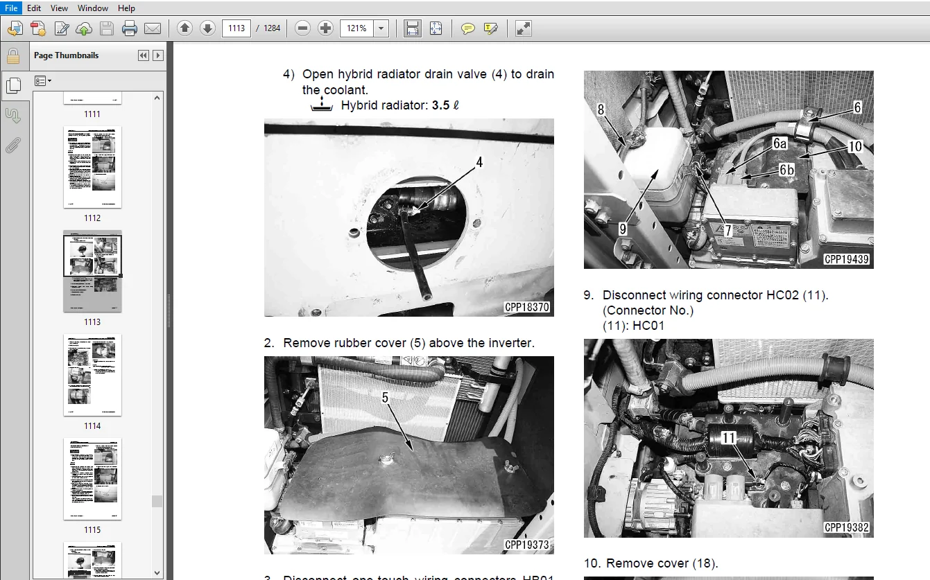
Draining and adding coolant and bleeding air for hybrid system 2
Removal and installation of hybrid radiator assembly 7
Removal and installation of water pump assembly for hybrid system 10
Removal and installation of inverter assembly 13
Removal and installation of inverter and capacitor assembly 17
Draining and adding generator lubricating oil 23
Removal and installation of tandem pump assembly 25
Removal and installation of motor-generator and housing assembly 28
Removal and installation of swing electric motor assembly 37
Power train SEN05259-01
Removal and installation of final drive assembly 2
Disassembly and assembly of final drive assembly 3
SEN05223-05
PC200, 200LC-8E0 (Hybrid) 00-100 13
100 Index
Table of contents
Removal and installation of “swing electric motor and swing machinery assembly” 11
Disassembly and assembly of swing machinery assembly 15
Removal and installation of swing circle assembly 29
Undercarriage and frame SEN05260-01
Disassembly and assembly of carrier roller assembly 2
Disassembly and assembly of track roller assembly 5
Disassembly and assembly of idler assembly 7
Disassembly and assembly of recoil spring assembly 10
Removal and installation of sprocket 12
Expansion and installation of track shoe assembly 13
Removal and installation of revolving frame assembly 16
Removal and installation of counterweight assembly 18
Hydraulic system SEN05261-01
Removal and installation of center swivel joint assembly 2
Disassembly and assembly of center swivel joint assembly 4
Removal and installation of hydraulic tank assembly 5
Removal and installation of control valve assembly 10
Disassembly and assembly of control valve assembly 14
Removal and installation of hydraulic pump assembly 18
Removal and installation of oil seal in hydraulic pump input shaft 22
Disassembly and assembly of work equipment PPC valve assembly 23
Disassembly and assembly of travel PPC valve assembly 25
Disassembly and assembly of hydraulic cylinder assembly 28
Work equipment Body SEN05262-00
Removal and installation of work equipment assembly 2
Cab and its attachments SEN05263-00
Removal and installation of operator’s cab assembly 2
Removal and installation of operator cab glass (stuck glass) 6
Removal and installation of front window assembly 15
Removal and installation of floor frame assembly 22
Removal and installation of air conditioner unit assembly 27
Electric system SEN05264-01
Removal and installation of KOMTRAX terminal 2
Removal and installation of monitor assembly 3
Removal and installation of pump controller assembly 5
Removal and installation of engine controller assembly 8
90 Diagrams and Drawings
Hydraulic diagrams and drawings SEN05266-01
Hydraulic circuit diagram 3
Electrical diagrams and drawings SEN05267-01
Electrical circuit diagram 3
Connector list and sterogram 17
KOMATSU PC200-8 PC200LC-8 HYDRAULIC EXCAVATOR SHOP MANUAL 1001 AND UP – PDF DOWNLOAD:
IMAGES PREVIEW OF THE MANUAL:
PLEASE NOTE:
- This is the same manual used by the DEALERSHIPS to SERVICE your vehicle.
- The manual can be all yours – Once payment is complete, you will be taken to the download page from where you can download the manual. All in 2-5 minutes time!!
- Need any other service / repair / parts manual, please feel free to contact us at heydownloadss @gmail.com . We may surprise you with a nice offer


