Komatsu PC200-8M0 PC200LC-8M0 PC220-8M0 PC220LC-8M0 Excavator Shop Manual SEN06109-13 – PDF DOWNLOAD
$39.95
Komatsu PC200-8M0 PC200LC-8M0 PC220-8M0 PC220LC-8M0 Excavator Shop Manual SEN06109-13 – PDF DOWNLOAD
SERIAL NUMBERS
PC200- 400001 and up
PC200LC- 400001 and up
PC220- 100001 and up
PC220LC- 100001 and up
Description
Komatsu PC200-8M0 PC200LC-8M0 PC220-8M0 PC220LC-8M0 Excavator Shop Manual SEN06109-13 – PDF DOWNLOAD
FILE DETAILS:
Komatsu PC200-8M0 PC200LC-8M0 PC220-8M0 PC220LC-8M0 Excavator Shop Manual SEN06109-13 – PDF DOWNLOAD
Language : English
Pages : 1450
Downloadable : Yes
File Type : PDF
IMAGES PREVIEW OF THE MANUAL:
TABLE OF CONTENTS:
Komatsu PC200-8M0 PC200LC-8M0 PC220-8M0 PC220LC-8M0 Excavator Shop Manual SEN06109-13 – PDF DOWNLOAD
SERIAL NUMBERS
PC200- 400001 and up
PC200LC- 400001 and up
PC220- 100001 and up
PC220LC- 100001 and up
Cover 1
00 Index and foreword 3
100 Index 3
Composition of shop manual 4
Table of contents 6
200 Foreword and general information 17
Foreword, safety and general information 18
How to read the shop manual 25
Explanation of terms for maintenance standard 27
Handling equipment of fuel system devices 29
Handling of intake system parts 30
Handling of hydraulic equipment 31
Method of disconnecting and connecting of push-pull type coupler 33
Handling of electrical equipment 36
How to read electric wire code 45
Precautions when performing operation 48
Practical use of KOMTRAX 51
Standard tightening torque table 52
List of abbreviation 56
Conversion table 61
01 Specification 67
100 Specification and technical data 67
Specification dimension drawings 68
Working range diagram 69
Specifications 70
Weight table 74
Table of fuel, coolant and lubricants 78
10 Structure, function and maintenance standard 81
100 Engine and cooling system 81
Engine related parts 82
Radiator, oil cooler, aftercooler and fuel cooler 83
200 Power train 85
Power train 86
Final drive 88
Swing machinery 92
Swing circle 96
300 Undercarriage and frame 99
Track frame and recoil spring 100
Idler 102
Carrier roller 104
Track roller 105
Track shoe 106
401 Hydraulic system, Part 1 113
Hydraulic equipment layout drawing 114
Hydraulic tank and filter 116
Hydraulic pump 118
Pilot oil filter 140
402 Hydraulic system, Part 2 143
Control valve 144
CLSS 155
Functions and operation by valve 159
403 Hydraulic system, Part 3 201
Swing motor 202
Center swivel joint 210
Travel motor 212
PPC valve 222
Valve control 242
Solenoid valve 244
PPC accumulator 246
Return oil filter 247
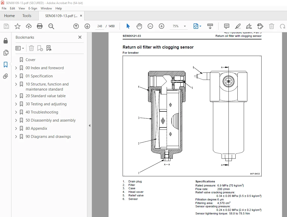
Return oil filter with clogging sensor 248
Attachment circuit selector valve 250
Hydraulic cylinder 252
500 Work equipment 257
Work equipment 258
Dimensions of arm 266
Dimensions of bucket 268
600 Electrical system 271
Engine control 272
Electrical control system 282
Machine monitor system 305
Sensor 326
KOMTRAX system 330
Clogging detection system of additional filter for breaker 333
20 Standard value table 335
100 Standard service value table 335
Standard value table for engine related parts 336
Standard value table for chassis related parts 338
30 Testing and adjusting 357
101 Testing and adjusting, Part 1 357
Tools for testing, adjusting, and troubleshooting 359
Sketch of special tool 363
Testing engine speed 364
Testing intake air pressure (boost pressure) 365
Testing exhaust gas color 366
Adjusting valve clearance 367
Testing compression pressure 369
Testing blowby pressure 372
Testing engine oil pressure 373
Handling fuel system parts 374
Releasing residual pressure from fuel system 374
Testing fuel pressure 375
Handling reduced cylinder mode operation 378
Handling no-injection cranking operation 378
Testing fuel discharge, return and leak amount 379
Bleeding air from fuel circuit 382
Testing fuel circuit for leakage 383
Handling controller high voltage circuit 384
Testing and adjusting air conditioner compressor belt tension 385
Replacing alternator belt 386
Testing swing circle bearing clearance 387
Testing and adjusting track tension 388
Testing and adjusting oil pressure in work equipment, swing, and travel circuits 390
Testing control circuit source pressure 393
Testing and adjusting oil pressure in pump PC control circuit 394
Testing and adjusting oil pressure in pump LS control circuit 397
Testing solenoid valve output pressure 402
Testing PPC valve output pressure 405
Adjusting play of work equipment and swing PPC valves 407
Testing parts which cause hydraulic drift of work equipment 408
Releasing remaining pressure from hydraulic circuit 410
Testing oil leakage 411
Bleeding air from each part 414
Testing cab tipping stopper 416
Adjusting mirrors 417
Installation and adjustment of mirrors 418
Angle adjustment of rear view camera 421
102 Testing and adjusting, Part 2 425
Special functions of machine monitor 426
103 Testing and adjusting, Part 3 477
Handling voltage circuit of engine controller 478
Preparation work for troubleshooting of electrical system 479
Procedure for testing diodes 484
Handling battery disconnect switch 485
Pm Clinic service 486
40 Troubleshooting 497
100 Failure code table and fuse locations 497
Failure codes table 498
Fuse locations 505
200 General Information on troubleshooting 509
Symptom and troubleshooting numbers 510
Sequence of events in troubleshooting 512
Checks before troubleshooting 514
Classification and procedures for troubleshooting 516
Symptom and troubleshooting numbers 518
Information in troubleshooting table 520
Connector/electrical wiring connection table 522
Connector arrangement diagram 552
Connection table for connector pin numbers 558
T- branch box and T- branch adapter table 594
Troubleshooting method for open circuit in wiring harness of pressure sensor system 597
301 Troubleshooting by failure code, Part 1 601
Failure code [879AKA] 603
Failure code [879AKB] 603
Failure code [879BKA] 603
Failure code [879BKB] 603
Failure code [879CKA] 603
Failure code [879CKB] 603
Failure code [879DKZ] 604
Failure code [879EMC] 604
Failure code [879FMC] 604
Failure code [879GKX] 604
Failure code [989L00] 605
Failure code [989M00] 606
Failure code [989N00] 607
Failure code [AA10NX] 608
Failure code [AB00KE] 610
Failure code [B@BAZG] 613
Failure code [B@BAZK] 614
Failure code [B@BCNS] 616
Failure code [B@BCZK] 617
Failure code [B@HANS] 619
Failure code [CA111] 620
Failure code [CA115] 621
Failure code [CA122] 622
Failure code [CA123] 625
Failure code [CA131] 628
Failure code [CA132] 631
Failure code [CA144] 634
Failure code [CA145] 637
Failure code [CA153] 640
Failure code [CA154] 643
Failure code [CA155] 646
Failure code [CA187] 647
Failure code [CA221] 649
Failure code [CA222] 652
Failure code [CA227] 655
Failure code [CA234] 656
Failure code [CA238] 657
Failure code [CA271] 659
Failure code [CA272] 661
302 Troubleshooting by failure code, Part 2 665
Failure code [CA322] 667
Failure code [CA323] 670
Failure code [CA324] 673
Failure code [CA325] 676
Failure code [CA331] 679
Failure code [CA332] 682
Failure code [CA342] 685
Failure code [CA351] 686
Failure code [CA352] 687
Failure code [CA386] 689
Failure code [CA428] 690
Failure code [CA429] 692
Failure code [CA435] 694
Failure code [CA441] 696
Failure code [CA442] 699
Failure code [CA449] 700
Failure code [CA451] 702
Failure code [CA452] 705
Failure code [CA488] 708
Failure code [CA553] 709
Failure code [CA559] 710
Failure code [CA689] 712
Failure code [CA731] 715
Failure code [CA757] 718
Failure code [CA778] 719
Failure code [CA2185] 724
Failure code [CA2186] 727
Failure code [CA2249] 729
Failure code [CA2311] 730
Failure code [CA2555] 731
Failure code [CA2556] 734
303 Troubleshooting by failure code, Part 3 739
Failure code [D110KB] 740
Failure code [D19JKZ] 742
Failure code [D811MC] 745
Failure code [D862KA] 746
Failure code [D8AQKR] 747
Failure code [DA22KK] 750
Failure code [DA25KP] 753
Failure code [DA26KP] 756
Failure code [DA29KQ] 759
Failure code [DA29KQ] 762
Failure code [DA2QKR] 764
Failure code [DAF0MB] 767
Failure code [DAF0MC] 767
Failure code [DAF8KB] 768
Failure code [DAF9KQ] 770
Failure code [DAFGMC] 771
Failure code [DAFQKR] 772
Failure code [DAZ9KQ] 773
Failure code [DAZQKR] 774
Failure code [DB2QKR] 775
Failure code [DGH2KB] 781
Failure code [DHA4KA] 783
Failure code [DHPAMA] 784
Failure code [DHPBMA] 787
304 Troubleshooting by failure code, Part 4 791
Failure code [DHS3MA] 792
Failure code [DHS4MA] 795
Failure code [DHS8MA] 798
Failure code [DHS9MA] 801
Failure code [DHSAMA] 804
Failure code [DHSBMA] 807
Failure code [DHSCMA] 810
Failure code [DHSDMA] 813
Failure code [DHSFMA] 816
Failure code [DHSGMA] 819
Failure code [DHSHMA] 822
Failure code [DHSJMA] 825
Failure code [DHX1MA] 828
Failure code [DR21KX] 832
Failure code [DR31KX] 834
Failure code [DV20KB] 835
Failure code [DW43KA] 837
Failure code [DW43KB] 839
Failure code [DW45KA] 841
Failure code [DW45KB] 844
Failure code [DW91KA] 847
Failure code [DW91KB] 849
305 Troubleshooting by failure code, Part 5 853
Failure code [DWA2KA] 854
Failure code [DWA2KB] 856
Failure code [DWK0KA] 858
Failure code [DWK0KB] 860
Failure code [DWK2KA] 862
Failure code [DWK2KB] 864
Failure code [DXA8KA] 866
Failure code [DXA8KB] 869
Failure code [DXA9KA] 872
Failure code [DXA9KB] 875
Failure code [DXE0KA] 878
Failure code [DXE0KB] 880
Failure code [DXE4KA] 882
Failure code [DXE4KB] 884
Failure code [DXE5KA] 886
Failure code [DXE5KB] 888
Failure code [DXE6KA] 890
Failure code [DXE6KB] 892
Failure code [DY20KA] 894
Failure code [DY20MA] 897
Failure code [DY2CKB] 900
Failure code [DY2DKB] 903
Failure code [DY2EKB] 905
400 Troubleshooting of electrical system (E-mode) 909
Before troubleshooting for electrical system 911
Information described in troubleshooting table 913
E-1 Engine does not start (engine does not rotate) 915
E-2 Preheating system does not work 924
E-3 Machine monitor displays nothing when starting switch is turned to ON position 930
E-4 When starting switch is turned to ON position (with engine stopped), basic check items light up 933
E-5 Caution item lights up while the engine is running 934
E-6 Caution item lights up while the engine is running 939
E-7 Fuel gauge does not indicate correct level 942
E-8 Engine coolant temperature gauge does not indicate correct temperature 945
E-9 Hydraulic oil temperature gauge does not indicate correct temperature 947
E-10 Contents of display on machine monitor are different from actual machine model 950
E-11 Some areas of machine monitor screen are not displayed 952
E-12 Function switch does not work 952
E-13 Automatic warm-up system does not work (in cold weather) 953
E-14 Auto-deceleration function does not work properly 955
E-15 Working mode does not change 957
E-16 Travel speed does not change 958
E-17 Alarm buzzer does not stop sounding 960
E-18 Service meter is not displayed while starting switch is in OFF position 960
E-19 Service mode cannot be selected 961
E-20 All work equipment, swing and travel do not work, or lock is not available 962
E-21 Swing parking brake does not work properly 965
E-22 One-touch power maximizing function does not work properly 969
E-23 Travel alarm does not sound or does not stop sounding 972
E-24 Horn does not sound or does not stop sounding 974
E-25 Wiper or window washer does not operate 978
E-26 “Boom LOWER” is not displayed correctly via monitoring function 981
E-27 “Arm OUT” is not displayed correctly via monitoring function 981
E-28 “Arm IN” is not displayed correctly via monitoring function 982
E-29 “Boom RAISE” is not displayed correctly via monitoring function 982
E-30 “Bucket CURL” is not displayed correctly via monitoring function 982
E-31 “Bucket DUMP” is not displayed correctly via monitoring function 983
E-32 “Swing” is not displayed correctly via monitoring function 983
E-33 “Travel” is not displayed correctly via monitoring function 983
E-34 “Service” is not displayed correctly via monitoring function 984
E-35 Attachment hydraulic circuit cannot be changed 987
E-36 KOMTRAX system does not operate normally 988
E-37 Breaker clogging caution lamp lights up when breaker is not used 990
500 Troubleshooting of hydraulic and mechanical system (H-mode) 993
System diagram of hydraulic and mechanical system 996
Failure mode and cause table 998
Information in troubleshooting table 1000
H-1 All work equipment, swing and travel speed are all slow, or there is no force 1001
H-2 Engine speed drops significantly or engine stalls 1004
H-3 All work equipment, swing and travel do not work 1006
H-4 Unusual noise is heard from the vicinity of the hydraulic pump 1007
H-5 Fine control performance or response is poor 1008
H-6 Boom speed is low or power is insufficient 1009
H-7 Arm speed is low or power is insufficient 1013
H-8 Bucket speed is low or power is insufficient 1017
H-9 Work equipment does not move in single operation 1019
H-10 Hydraulic drift of work equipment is large 1020
H-11 Time lag of work equipment is large 1024
H-12 When certain work equipment is relieved hydraulically, other work equipment moves 1025
H-13 One-touch power maximization function does not work 1026
H-14 When combining operations of work equipment, equipment subject to heavier loads moves slower 1027
H-15 Boom RAISE is slow in Swing + Boom RAISE operation 1028
H-16 When combining swing and travel operations, travel speed drops significantly 1029
H-17 Travel deviation is detected 1030
H-18 Travel speed is slow 1032
H-19 Machine does not steer well or steering power is low 1035
H-20 Travel speed does not change, or travel speed is too slow or too fast 1039
H-21 One track does not move 1041
H-22 Machine does not swing 1043
H-23 Swing acceleration or swing speed is low 1046
H-24 Upper structure overruns excessively when it stops swinging 1049
H-25 Shock is significant when upper structure stops swinging 1052
H-26 An unusual loud noise is heard when the upper structure stops swinging 1053
H-27 Swing drift on a slope is significant 1054
H-28 Attachment circuit cannot be changed 1057
H-29 Oil flow in the attachment circuit cannot be changed 1058
600 Troubleshooting of engine (S-mode) 1061
Method of using troubleshooting chart 1062
S-1 Startability is poor 1066
S-2 Engine does not start 1067
S-3 Engine does not pick up smoothly 1070
S-4 Engine stops during operation 1071
S-5 Engine runs rough or is unstable 1072
S-6 Engine lacks power 1073
S-7 Exhaust smoke is black (incomplete combustion) 1074
S-8 Oil consumption is excessive (or exhaust smoke is blue) 1075
S-9 Oil becomes contaminated early 1076
S-10 Fuel consumption is excessive 1077
S-11 Oil is in coolant (or coolant spurts or coolant level goes down) 1078
S-12 Oil pressure drops 1079
S-13 Oil level rises (coolant or fuel in oil) 1080
S-14 Coolant temperature rises too high (overheating) 1081
S-15 Unusual noise is made 1082
S-16 Vibration is excessive 1083
50 Disassembly and assembly 1085
100 General information on disassembly and assembly 1085
How to read this manual 1086
Coating materials list 1088
Special tools list 1091
Sketches of special tools 1096
200 Engine and cooling system 1101
Removal and installation of fuel supply pump assembly 1102
Removal and installation of fuel injector assembly 1106
Removal and installation of engine front oil seal 1113
Removal and installation of engine rear oil seal 1118
Removal and installation of cylinder head assembly 1121
Removal and installation of radiator assembly 1136
Removal and installation of hydraulic oil cooler assembly 1138
Removal and installation of aftercooler assembly 1140
Removal and installation of fuel cooler assembly 1143
Removal and installation of engine and hydraulic pump assembly 1144
300 Power train 1155
Removal and installation of final drive assembly 1156
Disassembly and assembly of final drive assembly 1158
Removal and installation of swing motor and swing machinery assembly 1176
Disassembly and assembly of swing motor and swing machinery assembly 1178
Removal and installation of swing circle assembly 1188
400 Undercarriage and frame 1191
Disassembly and assembly of carrier roller assembly 1192
Disassembly and assembly of track roller assembly 1195
Removal and installation of idler and idler cushion assembly 1197
Disassembly and assembly of idler 1198
Disassembly and assembly of idler cushion 1201
Removal and installation of sprocket 1203
Separation and connection of track shoe assembly 1204
Removal and installation of revolving frame assembly 1208
Removal and installation of counterweight assembly 1210
500 Hydraulic system 1213
Removal and installation of center swivel joint assembly 1214
Disassembly and assembly of center swivel joint assembly 1216
Removal and installation of hydraulic tank assembly 1217
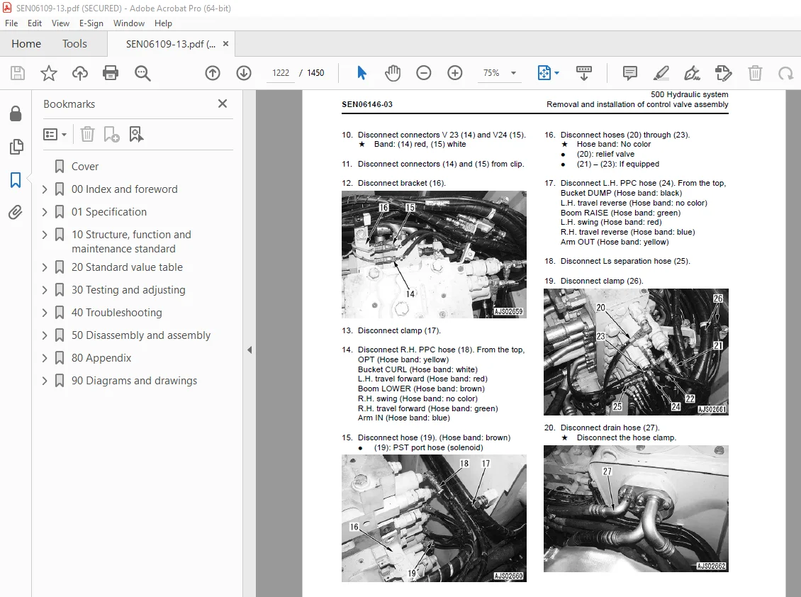
Removal and installation of control valve assembly 1221
Disassembly and assembly of control valve 1226
Removal and installation of hydraulic pump assembly 1231
Removal and installation of oil seal in hydraulic pump input shaft 1235
Disassembly and assembly of work equipment PPC valve assembly 1236
Disassembly and assembly of travel PPC valve 1238
Disassembly and assembly of work equipment cylinder 1240
600 Work equipment 1249
Removal and installation of work equipment assembly 1250
700 Cab and its attachments 1255
Removal and installation of operator’s cab assembly 1256
Removal and installation of operator cab glass (stuck glass) 1259
Removal and installation of front window assembly 1269
Removal and installation of floor frame assembly 1276
Removal and installation of air conditioner unit assembly 1280
REMOVE AND INSTALL WORK EQUIPMENT CONTROL LEVER ASSEMBLY 1285
800 Electrical system 1299
Removal and installation of machine monitor assembly 1300
Removal and installation of engine controller assembly 1302
Removal and installation of pump controller assembly 1304
Removal and installation of KOMTRAX terminal assembly 1306
Removal and installation of clogging caution lamp for breaker 1307
80 Appendix 1309
100 Air conditioner 1309
Precautions for refrigerant 1311
Air conditioner component 1312
Configuration and function of refrigeration cycle 1314
Outline of refrigeration cycle 1315
Air conditioner unit 1317
Air conditioner controller 1323
Compressor 1324
Condenser and Modulator 1325
Sensor 1326
Procedure for testing and troubleshooting 1328
Circuit diagram and arrangement of connector pins 1330
System diagram 1332
Parts and connectors layout 1334
Testing air leakage (duct) 1337
Testing with self-diagnosis function 1339
Testing vent (mode) changeover 1341
Testing FRESH/RECIRC air changeover 1342
Testing sunlight sensor 1343
Testing (dual) pressure switch for refrigerant 1344
Testing relays 1345
Troubleshooting chart 1 1346
Troubleshooting chart 2 1348
Information in troubleshooting table 1350
Failure code list related to air conditioner 1351
Failure code [879AKA] A/C Inner sensor Open Circuit 1352
Failure code [879AKB] A/C Inner sensor Short Circuit 1353
Failure code [879BKA] A/C Outer sensor Open Circuit 1354
Failure code [879BKB] A/C Outer sensor Short Circuit 1356
Failure code [879CKA] Ventilating sensor Open Circuit 1358
Failure code [879CKB] Ventilating sensor Short Circuit 1359
Failure code [879DKZ] Sunlight sensor Open or Short Circuit 1360
Failure code [879EMC] Ventilating Damper Abnormality 1362
Failure code [879FMC] Air Mix Damper Abnormality 1363
Failure code [879GKX] Refrigerant Abnormality 1364
Troubleshooting for power supply and CAN communication system (Air conditioner does not operate) 1366
Troubleshooting for compressor and refrigerant system (Air is not cooled) 1368
Troubleshooting for blower motor system (No air comes out or air flow is abnormal) 1372
Troubleshooting for FRESH/RECIRC air changeover 1374
Troubleshooting with gauge pressure 1376
Connection of service tool 1378
Precautions for disconnecting and connecting air conditioner piping 1380
Handling of compressor oil 1382
Desiccant replacement procedure 1384
90 Diagrams and drawings 1387
100 Hydraulic diagrams and drawings 1387
Symbols in hydraulic circuit diagram 1388
Hydraulic circuit diagram 1391
Hydraulic circuit diagram (Arm crane specification) 1399
200 Electrical diagrams and drawings 1405
Symbols in electric circuit diagram 1406
Electrical circuit diagram 1409
Wiring harness diagram 1429
DESCRIPTION:
Komatsu PC200-8M0 PC200LC-8M0 PC220-8M0 PC220LC-8M0 Excavator Shop Manual SEN06109-13 – PDF DOWNLOAD
SERIAL NUMBERS
PC200- 400001 and up
PC200LC- 400001 and up
PC220- 100001 and up
PC220LC- 100001 and up
How to read the shop manual
Composition of shop manual
q This shop manual describes the technical information required for the services performed in a workshop.
The shop manual is divided into the following chapters for the convenience of use.
00. Index and foreword
q This section includes the index, foreword, safety and basic information.
01. Specification
q This section explains the specifications of the machine.
10. Structure, function and maintenance standard
q This section explains the structure, function, and maintenance standard values of each component. The
structure and function sub-section explains the structure and function of each component. It serves not
only to give an understanding of the structure, but also serves as reference material for troubleshooting.
The maintenance standard sub-section explains the criteria and remedies for disassembly and service.
20. Standard value table
q The standard values for a new machine and trouble shooting are described. This standard value table is
used for testing and adjusting, and determining a failure at troubleshooting.
30. Testing and adjusting
q This section describes the measuring tools and how to measure, and how to adjust various parts. As for
the standard value and failure criterion, see the standard value table.
40. Troubleshooting
q This section describes the troubleshooting in a suspected area when a failure occurs and the remedy for
the failure. Troubleshooting is described by each failure mode.
50. Disassembly and assembly
q This section explains the procedures for removing, installing, disassembling, and assembling each part
or component and the special tools for the works as well as precautions for doing them safely. In addition,
tightening torque, and quantity and weight of coating material, oil, grease, and coolant required for
the works are also explained.
80. Appendix
q The structure and function, testing and adjusting, and troubleshooting for all of the other components or
equipment which can not be separately classified are explained together in the appendix.
90. Diagrams and drawings
q This section gives hydraulic circuit diagrams and electrical circuit diagrams.
S.V 30/12/24


